

Operation and Maintenance Manual for
Operation and Maintenance Manual for
Operation and Maintenance Manual for

Create successful ePaper yourself
Turn your PDF publications into a flip-book with our unique Google optimized e-Paper software.
KFZSD 1”/1.5” <strong>Manual</strong> 01/04 Rev. 1 SYSTEM INSTALLATION<br />
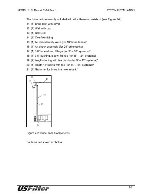
The brine tank assembly included with all softeners consists of (see Figure 2-2):<br />
11. (1) Brine tank with cover<br />
12. (1) Well with cap<br />
13. (1) Salt Grid<br />
14. (1) Overflow fitting<br />
15. (1) Air check/safety valve (<strong>for</strong> 18” brine tanks)*<br />
16. (1) Air check assembly (<strong>for</strong> 24” brine tanks)<br />
17. (1) 3/8” tube elbow, fittings (<strong>for</strong> 9” – 16” systems)*<br />
18. (1) 0.5” bushing, elbow, fittings (<strong>for</strong> 18” – 24” systems)<br />
19. (2) lengths tubing with tee (<strong>for</strong> duplex 9” – 12” systems)*<br />
20. (1) length 18’ tubing with tee (<strong>for</strong> 14” – 24” systems)*<br />
21. (1) Grommet <strong>for</strong> brine line hole in tank*<br />
14<br />
18<br />
13<br />
16<br />
12<br />
11<br />
Figure 2-2: Brine Tank Components<br />
* = items not shown in photos<br />
2-2


