

Operation and Maintenance Manual for
Operation and Maintenance Manual for
Operation and Maintenance Manual for

Create successful ePaper yourself
Turn your PDF publications into a flip-book with our unique Google optimized e-Paper software.
KFZSD 1”/1.5” <strong>Manual</strong> 01/04 Rev. 1 SYSTEM INSTALLATION<br />
2.4 VALVE AND PIPING INSTALLATION<br />
CAUTION Be<strong>for</strong>e installing the valve, remove the tape or cap from the top of the<br />
riser pipe.<br />
NOTE: During installation, refer to Table 1-1 <strong>for</strong> injector sizes <strong>and</strong> DLFC sizes.<br />
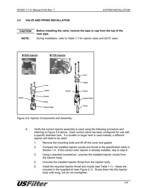
Figure 2-6: Injector Components <strong>and</strong> Assembly<br />
A. Verify the correct injector assembly is used using the following procedure <strong>and</strong><br />
referring to Figure 2-6 above. Each control valve has been configured <strong>for</strong> use with<br />
a specific diameter tank. If a smaller or larger tank is used instead, a different<br />
injector will need to be used:<br />
1. Remove the mounting bolts <strong>and</strong> lift off the cover <strong>and</strong> gasket.<br />
2. Compare the installed injector nozzle <strong>and</strong> throat to the specification table in<br />
Section 1.4. If the correct color injector is already installed, skip to step 6.<br />
3. Using a st<strong>and</strong>ard screwdriver, unscrew the installed injector nozzle from<br />
the injector body.<br />
4. Unscrew the installed injector throat from the injector body.<br />
5. Install the required injector throat <strong>and</strong> nozzle (see Table 1-1) – these are<br />
included in the supplied kit (see Figure 2-1). Screw them into the injector<br />
body until snug, but do not overtighten.<br />
2-6


