Create successful ePaper yourself
Turn your PDF publications into a flip-book with our unique Google optimized e-Paper software.
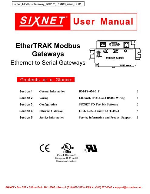
<strong>EtherTRAK</strong> <strong>Modbus</strong><br />
<strong>Gateways</strong><br />
Ethernet to Serial <strong>Gateways</strong><br />
Contents at a Glance:<br />
Section 1 General Information RM-PS-024-01F 3<br />
Section 2 Wiring Ethernet, RS232, and RS485 Wiring 5<br />
Section 3 Configuration SIXNET I/O Tool Kit Software 6<br />
Section 4 Ethernet <strong>Gateways</strong> ET-GT-232-1 and ET-GT-485-1 7<br />
Section 5 Service Information Service Information and Product Support 9<br />
Class I, Division 2,<br />
Groups A, B, C, and D<br />
Hazardous Locations<br />
SIXNET • Box 767 • Clifton Park, NY 12065 USA • +1 (518) 877-5173 • FAX +1 (518) 877-8346 • support@sixnetio.com
Protected Technology Policy<br />
SIXNET protects your investment in SIXNET systems with long-term planned technology and our unique Protected<br />
Technology Policy. We will continue to support the specified capabilities of standard SIXNET products for at least five years.<br />
We plan each product improvement and new feature to be upward compatible with existing designs and installations. Our<br />
goals are to make each new software release bring new power to your SIXNET systems and have every existing feature,<br />
applications program and data file continue to work.<br />
We protect your investment even further with a liberal five-year trade-in policy. Exchange standard products for upgraded<br />
versions of the same product to take advantage of new features and performance improvements at any time for five years. A<br />
prorated trade-in allowance will be given for your existing equipment.<br />
SIXNET protects your long-term productivity with state-of-the-art planned technology and continued support.<br />
SIXNET Statement of Limited Warranty<br />
Digitronics SIXNET (‘SIXNET’), manufacturer of SIXNET products, warrants to Buyer that products, except software,<br />
manufactured by SIXNET will be free from defects in material and workmanship. SIXNET’ obligation under this warranty<br />
will be limited to repairing or replacing, at SIXNET’ option, the defective parts within one year of the date of installation, or<br />
within 18 months of the date of shipment from the point of manufacture, whichever is sooner. Products may be returned by<br />
Buyer only after permission has been obtained from SIXNET. Buyer will prepay all freight charges to return any products to<br />
the repair facility designated by SIXNET.<br />
SIXNET further warrants that any software supplied as part of a product sale, except obsolete products, will be free from nonconformances<br />
with SIXNET published specifications for a period of 90 days from the time of delivery. While SIXNET<br />
endeavors to improve the features and performance of software associated with its products, no effort on the part of SIXNET<br />
to investigate, improve or modify SIXNET software at the request of a customer will obligate SIXNET in any way.<br />
For the convenience of existing customers, SIXNET continues to supply certain products that are classified as obsolete. No<br />
warranty on the software features of these products is stated or implied and SIXNET specifically is not obligated to improve<br />
the design of these products in any way. Information about the status of any product is available upon request and customers<br />
are advised to inquire about the status of older products prior to making a purchase.<br />
This limited warranty does not cover losses or damages which occur in shipment to or from Buyer or due to improper<br />
installation, maintenance, misuse, neglect or any cause other than ordinary commercial or industrial applications. In<br />
particular, SIXNET makes no warranties whatsoever with respect to implied warranties of merchantability or fitness for any<br />
particular purpose. All such warranties are hereby expressly disclaimed. No oral or written information or advice given by<br />
SIXNET or SIXNET’s representative shall create a warranty or in any way increase the scope of this warranty. This limited<br />
warranty is in lieu of all other warranties whether oral or written, expressed or implied. SIXNET's liability shall not exceed<br />
the price of the individual units, which are the basis of the claim. In no event shall SIXNET be liable for any loss of profits,<br />
loss of use of facilities or equipment, or other indirect, incidental or consequential damages.<br />
These products must not be used to replace proper safety interlocking. No software based device (or other solid state device)<br />
should ever be designed to be responsible for the maintenance of consequential equipment or personnel safety. In particular,<br />
SIXNET disclaims any responsibility for damages, either direct or consequential, that result from the use of this equipment in<br />
any application.<br />
Note: All information in this document applies to <strong>EtherTRAK</strong> <strong>Modbus</strong> <strong>Gateways</strong>, except where<br />
otherwise noted. Refer to the SIXNET I/O Tool Kit software online help system for detailed<br />
product specifications and configuration settings.<br />
ethernet modbus manual.doc Last Revised: March 2001
Section 1 General Information<br />
Overview This manual will help you install and maintain <strong>EtherTRAK</strong> <strong>Modbus</strong> <strong>Gateways</strong>. In summary,<br />
wiring for power, communications and I/O is connected to each unit. Then, setup choices are<br />
entered using the Remote I/O Tool Kit software and the system will be ready to run.<br />
Performance<br />
Specifications<br />
Power<br />
Wiring<br />
Section 1 General Information 3<br />
Use these<br />
<strong>EtherTRAK</strong><br />
<strong>Gateways</strong> to connect<br />
one or more <strong>Modbus</strong><br />
or SIXNET serial<br />
devices to Ethernet<br />
via RS232 or RS485.<br />
These general specifications apply to all <strong>EtherTRAK</strong> gateways. Refer to the individual data sheets<br />
or the SIXNET electronic catalog for complete specifications.<br />
Supply Voltage 10 - 30 VDC, 0.5 Watt typical (25 mA @ 24 VDC)<br />
Ethernet Protocols <strong>Modbus</strong>/TCP, <strong>Modbus</strong>/UDP, SIXNET/UDP<br />
Serial Protocols <strong>Modbus</strong> ASCII, <strong>Modbus</strong> RTU, SIXNET<br />
Ethernet Isolation 1200 Volts RMS (for 1 minute)<br />
Operating Temperature -30 to 70 °C<br />
Storage Temperature -40 to 85 °C<br />
Humidity 5 to 95% (non-condensing)<br />
Screw Terminals 14 AWG max. (tighten to 3.48 in-lbs. Max.)<br />
<strong>EtherTRAK</strong> gateways can be powered from the same DC source that is used to power your I/O<br />
devices. 10 to 30 VDC needs to be applied to terminals 2 and 3 of each gateway. Refer to the<br />
wiring diagram for each gateway for more information.<br />
The RM-PS-024-01 can be used to power your <strong>EtherTRAK</strong> gateways, instrumentation loops, and<br />
other devices. It operates on 85-264 VAC (47-63 Hz) or 120-370 VDC and outputs 24 VDC at up<br />
to 1 A. Refer to its data sheet for details. Refer to the figure below for the power connections.
Status LED<br />
Indication<br />
Status LED<br />
Wink Feature<br />
On, with a quick “OFF” BLINK (1.9 seconds ON, .1 seconds OFF) - The gateway is configured<br />
and fully operational, but has not received a valid request from the host for a time longer than the<br />
specified time out period. A communication time out has occurred.<br />
Full ON - The gateway is configured, fully operational, and has received communication from<br />
the host device before the timeout period expired. This is the desired LED indication during<br />
system operation.<br />
HALF BLINK (1 second ON, 1 second OFF) - The gateway is not adequately configured and<br />
requires a download from the SIXNET I/O Tool Kit program.<br />
Full OFF - There is no power to the gateway, or the status LED is being turned off intentionally<br />
by the SIXNET I/O Tool Kit during the module loading operation.<br />
Off, with a quick “ON” BLINK (1.9 seconds OFF, .1 seconds ON ) - The gateway failed selftest<br />
at initialization. It will not attempt communication and should be replaced.<br />
The “Status” LED may be intentionally winked (10 blinks/ second) by the SIXNET I/O Tool Kit<br />
program to visually identify the gateway when other modules are present.<br />
TD / RD LEDs The Receive Data (RD) LED will be ON when characters are being sent out the serial port.<br />
The Transmit Data (TD) LED will be ON when characters are being received into the serial port.<br />
ACT / LNK<br />
LEDs<br />
The activity (ACT) LED on an <strong>EtherTRAK</strong> gateway will flicker anytime there is traffic on the<br />
Ethernet network, regardless of whom the network messages are intended for.<br />
The link (LNK) LED will be ON whenever a valid link to another Ethernet device is detected.<br />
The best troubleshooting tools for <strong>EtherTRAK</strong> gateways are the Status, ACT, and LNK LEDs on<br />
each module.<br />
Each <strong>EtherTRAK</strong> Status LED indicates the health of the module and also the status of<br />
communication from the host device. You can use the Wink feature to provide continuous<br />
transmission to an <strong>EtherTRAK</strong> gateway. Note that an <strong>EtherTRAK</strong> gateway does not send a reply<br />
in response to a Wink command.<br />
Section 2 RS485 Wiring 4
Section 2 Ethernet, RS232, and RS485 Wiring<br />
Overview <strong>EtherTRAK</strong> gateways communicate with a master device (such as a PC, SIXTRAK Gateway, or<br />
VersaTRAK RTU) using 10BaseT Ethernet media. Electrical isolation is provided on the<br />
Ethernet port for increased reliability. Please follow normal Ethernet wiring practices when<br />
installing <strong>EtherTRAK</strong> gateways.<br />
RS232 Wiring<br />
Guidelines<br />
(ET-GT-232-1)<br />
RS485 Wiring<br />
Guidelines<br />
(ET-GT-485-1)<br />
Each <strong>EtherTRAK</strong> gateway has either a RS485 (2 wire) port or RS232 port. Follow the wiring<br />
guidelines below to achieve reliable RS485 or RS232 communication with your device.<br />
The RS232 port on the ET-GT-232-1 is a female DB9 that follows the DCE pin-out convention.<br />
Refer to the diagrams below for connection details.<br />
The RS485 port on the ET-GT-485-1 supports 2 wire (plus ground) party-line connections. It is<br />
recommended that the ground wire be connected to all stations to provide a common return. The<br />
RS485 on this <strong>EtherTRAK</strong> gateway is isolated from its internal circuitry, local power source, and<br />
Ethernet port to improve communications reliability. It is recommended that only 32 RS485<br />
devices be connected on any RS485 party-line, and that the termination be installed on the last<br />
device on each end of the RS485 network. Limiting the cabling to two network arms (segments)<br />
radiating from the master controller will yield the best signal results.<br />
This diagram shows an example of two RemoteTRAK modules off of an Ethernet gateway.<br />
Screw Torque All the screw terminals on the base should be tightened to a maximum of 3.48 in-lbs.<br />
Section 2 Ethernet, RS485 Wiring 5
Section 3 Configuration<br />
SIXNET I/O<br />
Tool Kit<br />
All configuration parameters are entered using the SIXNET I/O Tool Kit software, which stores all<br />
setup information into permanent memory in the <strong>EtherTRAK</strong> gateway. Configuration parameters<br />
are loaded to the gateway over Ethernet. Refer to the SIXNET I/O Tool Kit help for details.<br />
Here are the basic steps for configuring an <strong>EtherTRAK</strong> gateway.<br />
1. Connect power to the gateway.<br />
2. Connect your Ethernet to the gateway. Use a straight-through cable if you are connecting the<br />
gateway to an Ethernet hub or switch. Use a cross-wired cable if you are connecting the<br />
gateway directly to a PC. Make sure the LNK LED on the gateway is on solid (not blinking).<br />
3. Install and run the SIXNET I/O Tool Kit. Then select the Plug & Play Wizard to define the<br />
parameters for the gateway. Make sure to do the following:<br />
• Choose an IP address that is appropriate for your network. See the help file for details.<br />
• Enter in the serial number that is printed on a label on the gateway.<br />
• Choose a station (slave) number for the gateway that is unique from other gateways and<br />
the device you are interfacing to.<br />
• Select the appropriate RS232 or RS485 com parameters (protocol, baud rate, etc.) to<br />
match the device that you are interfacing to.<br />
4. Once you’ve completed the wizard, save your project file, and go to the Operations menu and<br />
select Load. This should set the IP address in the gateway and then load down your other<br />
parameters.<br />
If this load fails, here are some items to check:<br />
• Make sure the LNK LED is on solid. If it’s off or blinking then a typical cause is a bad<br />
cable, an incorrect cable, or you are plugged into the wrong port on your hub/switch.<br />
• Try to “ping” the gateway. Ping is a utility that comes with your PC. Go to a DOS window<br />
and type “ping” followed by the IP address of the gateway and then hit return. For<br />
example, “ping 10.1.0.1” (do not type the quotes). If you get an “unknown command”<br />
error then you need to install the TCP/IP Ethernet protocol on your computer. If you get<br />
“destination unreachable” then make sure the gateway’s IP address is valid with respect to<br />
the IP address and subnet mask of your computer. If you get “request timeout” then check<br />
all the items above.<br />
5. Once you establish that you can communicate with the gateway from the SIXNET I/O Tool Kit<br />
you then should attempt to communicate with your device using your master software (i.e.<br />
KepServer, Citect, Intellution, etc.).<br />
Note 1: The <strong>EtherTRAK</strong> gateways do not convert protocols. If the gateway’s serial port is<br />
configured for <strong>Modbus</strong> Passthru protocol then you must communicate to the gateway over Ethernet<br />
with <strong>Modbus</strong>/TCP or <strong>Modbus</strong>/UDP. If the gateway’s serial port is configured for SIXNET Passthru<br />
protocol then you must communicate to the gateway over Ethernet with the SIXNET protocol.<br />
Section 3 Configuration Tools 6
Section 4 Ethernet <strong>Gateways</strong><br />
ET-GT-232-1<br />
Overview<br />
Power and<br />
RS232 Wiring<br />
ET-GT-232-1 Ethernet to RS232 Converter<br />
This Ethernet to RS232 gateway is typically used in one of these situations:<br />
• To connect an older SIXNET device such as an IOMUX or Versamux to an Ethernet network<br />
• To connect a <strong>Modbus</strong> RS232 slave device to an Ethernet network<br />
• To connect a <strong>Modbus</strong> RS232 master device, such as a display, to an Ethernet network<br />
• To interchange between a telephone modem and Ethernet interface<br />
Ethernet Protocols Supported <strong>Modbus</strong>/TCP, <strong>Modbus</strong>/UDP and SIXNET<br />
Serial Protocols Supported <strong>Modbus</strong> ASCII, <strong>Modbus</strong> RTU and SIXNET<br />
Supply voltage 10 – 30 VDC, 0.5 watt typical<br />
Virtual Analog Outputs 16<br />
Virtual Discrete Outputs 16<br />
More information can be found in the on-line help of the SIXNET I/O Tool Kit program.<br />
This gateway operates on 10 to 30 volts DC. Connect this power to terminals 2 and 3. Connect<br />
terminal 1 to a suitable earth ground.<br />
In many cases a straight-through RS232 cable, such as the SIXNET VT-CABLE-MDM, can be<br />
used to connect the RS232 port of this gateway to a SIXNET or <strong>Modbus</strong> serial device.<br />
This gateway can be connected to an Ethernet hub with a straight-through 10BaseT Ethernet<br />
cable. Use a cross-wired cable if you are connecting directly to a PC or other Ethernet master<br />
device.<br />
I/O Registers The ET-GT-232-1 has sixteen virtual discrete output registers and sixteen virtual analog output<br />
registers. These are provided so that a master RS232 <strong>Modbus</strong> device (such as a display) can pass<br />
register values over Ethernet to a computer or other device.<br />
Function SIXNET Registers <strong>Modbus</strong> Registers<br />
Discrete Outputs Y0 – Y15 00001 – 00016<br />
Analog Outputs AY0 – AY15 40001 – 40016<br />
Section 9 Ethernet <strong>Gateways</strong> 7
ET-GT-485-1<br />
Overview<br />
Power and<br />
RS485 Wiring<br />
ET-GT-485-1 Ethernet to RS485 Converter<br />
This Ethernet to RS485 gateway is typically used in one of these situations:<br />
• To connect one or more <strong>Modbus</strong> RS485 slave devices to an Ethernet network<br />
• To connect a <strong>Modbus</strong> RS485 master device, such as a display, to an Ethernet network<br />
• To connect RemoteTRAK modules to an Ethernet network<br />
Ethernet Protocols Supported <strong>Modbus</strong>/TCP, <strong>Modbus</strong>/UDP and SIXNET<br />
Serial Protocols Supported <strong>Modbus</strong> ASCII, <strong>Modbus</strong> RTU and SIXNET<br />
Supply voltage 10 – 30 VDC, 0.5 watt typical<br />
Virtual Analog Outputs 16<br />
Virtual Discrete Outputs 16<br />
More information may be found in the on-line help of the SIXNET I/O Tool Kit program.<br />
This gateway operates on 10 to 30 volts DC. Connect this power to terminals 2 and 3. Connect<br />
terminal 1 to a suitable earth ground.<br />
Refer to the diagram below for RS485 wiring.<br />
This gateway can be connected to an Ethernet hub with a straight-through 10BaseT Ethernet<br />
cable. Use a cross-wired cable if you are connecting directly to a PC or other Ethernet master<br />
device.<br />
I/O Registers The ET-GT-485-1 has sixteen virtual discrete output registers and sixteen virtual analog output<br />
registers. These are provided so that a master RS485 <strong>Modbus</strong> device (such as a display) can pass<br />
register values over Ethernet to a computer or other device.<br />
Function SIXNET Registers <strong>Modbus</strong> Registers<br />
Discrete Outputs Y0 – Y15 00001 – 00016<br />
Analog Outputs AY0 – AY15 40001 – 40016<br />
Section 9 Ethernet <strong>Gateways</strong> 8
Section 5 Service Information<br />
Service<br />
Information<br />
Product<br />
Support<br />
We sincerely hope that you never experience a problem with any SIXNET product. If you do need<br />
service, call SIXNET at (518) 877-5173 and ask for Applications Engineering. A trained<br />
specialist will help you to quickly determine the source of the problem. Many problems are easily<br />
resolved with a single phone call. If it is necessary to return a unit to us, an RMA (Return Material<br />
Authorization) number will be given to you.<br />
SIXNET tracks the flow of returned material with our RMA system to ensure speedy service. You<br />
must include this RMA number on the outside of the box so that your return can be processed<br />
immediately.<br />
The applications engineer you are speaking with will fill out an RMA request for you. If the unit<br />
has a serial number, we will not need detailed financial information. Otherwise, be sure to have<br />
your original purchase order number and date purchased available.<br />
We suggest that you give us a repair purchase order number in case the repair is not covered under<br />
our warranty. You will not be billed if the repair is covered under warranty.<br />
Please supply us with as many details about the problem as you can. The information you supply<br />
will be written on the RMA form and supplied to the repair department before your unit arrives.<br />
This helps us to provide you with the best service, in the fastest manner. Normally, repairs are<br />
completed in two days. Sometimes difficult problems take a little longer to solve.<br />
If you need a quicker turnaround, ship the unit to us by air freight. We give priority service to<br />
equipment that arrives by overnight delivery. Many repairs received by mid-morning (typical<br />
overnight delivery) can be finished the same day and returned immediately.<br />
We apologize for any inconvenience that the need for repair may cause you. We hope that our<br />
rapid service meets your needs. If you have any suggestions to help us improve our service, please<br />
give us a call. We appreciate your ideas and will respond to them.<br />
For Your Convenience:<br />
Please fill in the following and keep this manual with your SIXNET system for future reference:<br />
P.O. #:__________________ Date Purchased: ___________________<br />
Purchased From:______________________________________________<br />
To obtain support for SIXNET products, call SIXNET and ask for applications engineering. Our<br />
phone numbers are:<br />
+1 (518) 877-5173 Office<br />
+1 (518) 877-8346 Fax<br />
e-mail: support@sixnetio.com<br />
Our mailing address:<br />
SIXNET<br />
331 Ushers Rd.<br />
P.O. Box 767<br />
Clifton Park, NY 12065<br />
Section 10 Service Information 9


