Piro Sensor Installation and operating manual - AmeriStar Energy
Piro Sensor Installation and operating manual - AmeriStar Energy
Piro Sensor Installation and operating manual - AmeriStar Energy

You also want an ePaper? Increase the reach of your titles
YUMPU automatically turns print PDFs into web optimized ePapers that Google loves.
PIRO-SENSOR<br />
Ameristar <strong>Energy</strong>, LLC<br />
<strong>Installation</strong> <strong>and</strong> Operating Instructions<br />
For S-PIRW1, S-PIRTW1,<br />
<strong>and</strong> S-PIRPW1<br />
Ameristar <strong>Energy</strong>, LLC PO BOX “C” BEDMINSTER, PA 18910<br />
www.ameristareps.com 7000-0006 rev. 122211
Description Page No.<br />
Overview<br />
Specifications<br />
- Environmental/Electrical<br />
- Wire colors <strong>and</strong> functions<br />
- Viewing angles<br />
Mounting <strong>and</strong> <strong>Installation</strong> with thermostat<br />
Mounting <strong>and</strong> <strong>Installation</strong> with PTAC unit<br />
<strong>Piro</strong> sensor-thermostat wiring diagrams<br />
<strong>Piro</strong> sensor-PTAC wiring diagrams<br />
<strong>Piro</strong> sensor Programming<br />
<strong>Piro</strong> sensor-thermostat testing<br />
<strong>Piro</strong> sensor-PTAC testing<br />
Table of Contents<br />
3<br />
3<br />
3<br />
4<br />
4<br />
5<br />
7<br />
9<br />
10<br />
11<br />
12<br />
Page 2
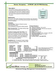
The <strong>Piro</strong>-<strong>Sensor</strong> is a dual sensing occupancy sensor that uses both motion <strong>and</strong> infrared to sense<br />
the presence of people.<br />
The sensor covers small motion up to 20 feet <strong>and</strong> large motion up to 50 feet. The motion<br />
sensor continuously searches for occupants.<br />
There is a selectable time delay (1 to 12 hours) that keeps the <strong>Piro</strong>-<strong>Sensor</strong> from placing the<br />
thermostat or PTAC unit into the unoccupied mode prematurely.<br />
The <strong>Piro</strong>-<strong>Sensor</strong> detects changes in the infrared energy given off by occupants as they move<br />
within the <strong>Piro</strong>-<strong>Sensor</strong>’s field-of-view. When occupants are detected, an internal relay is<br />
set to the occupied mode. If no occupants are detected duringthe selected time delay period,<br />
the <strong>Piro</strong>-<strong>Sensor</strong> changes the internal relay to the unoccupied mode at the end of the time delay<br />
period. The time delay setting should be set so the room/building does not change from<br />
occupied to unoccupied in less than two hours.<br />
NOTE:<br />
Environment/Electrical:<br />
Internal relay (Occupied Mode)<br />
Brown<br />
(Common)<br />
Green (NO)<br />
Internal relay (Un-occupied Mode)<br />
Brown<br />
(Common)<br />
1. Humidity: 20 to 90% non-condensing<br />
2. Ambient temperature: 14° to 160°F<br />
3. Storage temperature: 14° to 160°F<br />
4. Operating voltage: 12-24VAC/VDC<br />
5. Relay contact rating: 1A @24vac<br />
0.5A @120vac<br />
Overview<br />
Internal relay energized during Un-occupied<br />
mode<br />
Specifications<br />
Gray (NC)<br />
Gray (NC)<br />
Green (NO)<br />
Wiring colors <strong>and</strong> functions:<br />
Black - 12-24VAC/VDC<br />
White - Common<br />
Brown - Relay common<br />
Green - Relay normally open contact<br />
Gray - Relay normally closed contact<br />
Page 3
Viewing angles:<br />
The Occupancy sensor’s location <strong>and</strong> position is critical, as the person must be viewed when they<br />
are NOT generally moving, such as in bed, sitting, watching TV, etc. (See figure below) The time delay<br />
is reset every time the person’s motion is observed by the sensor. Therefore, the Occupancy sensor<br />
does not necessarily have to be positioned to view the people at all times. Periodic movement in front<br />
of the sensor will reset the time delay function.<br />
Corner mount with<br />
2” spacer<br />
Small motion (e.g. H<strong>and</strong> movements) detected up to 30 ft.<br />
Large motion (e.g. Walking) detected up to 50 ft.<br />
Designed for 5’.6”mounting<br />
If you need to get a closed view of the wall, in which the “Occupancy <strong>Sensor</strong>” is mounted on, you will<br />
need a spacer to angle the sensor down towards the floor.<br />
Mounting <strong>and</strong> installation with thermostat<br />
The <strong>Piro</strong>-<strong>Sensor</strong> has a tilt adjustment so it can be mounted anywhere between 4’ to 5’6”. If the sensor will<br />
be mounted any higher, the enclosed spacer must be used.<br />
Fig. 1<br />
1. Hold back of sensor <strong>and</strong> remove the pin from the top (Fig.1)<br />
2. Grasp the front <strong>and</strong> the back of the sensor <strong>and</strong> carefully<br />
separate the two pieces.<br />
Pin<br />
Back case<br />
Flat wall<br />
mount with<br />
7/8” spacer<br />
! Caution REMOVE POWER BEFORE DOING ANY WORK!<br />
<strong>Installation</strong> shall be done by a licensed electrician <strong>and</strong>/or licensed HVAC contractor. <strong>Installation</strong><br />
<strong>and</strong> wiring shall adhere to all state, local <strong>and</strong> federal codes <strong>and</strong> requirements.<br />
Page 4
3. Place the back plate at the desired mounting location <strong>and</strong><br />
mark the location of the mounting holes <strong>and</strong> wire<br />
Mounting Holes<br />
hole (Fig 2). The sensor can be mounted<br />
next to the thermostat provided the field-of-view is not<br />
obstructed.<br />
Fig.2<br />
4. Drill one hole for sensor wires <strong>and</strong> two mounting holes for mounting anchors. Insert the plastic<br />
anchors (provided) into the mounting holes.<br />
5. Fish a wire cable through the wire hole to the thermostat junction box.<br />
6. Insert the fished wires from the wall through the center hole on the back of the case.<br />
7. If mounting sensor with spacer see MOUNTING WITH SPACER step #17. Place the back case<br />
on the wall <strong>and</strong> insert the screw through the mounting hole to the anchors.<br />
8. Connect the sensor wires to the fished wires. Push extra wire length back into the hole.<br />
9. Secure the back plate to the wall with screws.<br />
10. Hold the front of the case <strong>and</strong> place the indentations (inside front case) under the prongs on the case<br />
back.<br />
11. Push the front of the case towards the wall until the pin holes match up.<br />
12. Place the pin in the appropriate hole based on the mounting height listed below.<br />
Tilt adjustments: Note: Pin position 1 is farthest from the<br />
wall when sensor is mounted<br />
Mounting Pin<br />
Pin in position 1<br />
Height Position<br />
5’ 6” 1 = (-5°)<br />
5’ 2 = (0°)<br />
4’ 3 = (+5°)<br />
13. Verify the input voltage at the thermostat junction box is 24VAC. If the input voltage is 120/240 VAC<br />
a transformer will need to be connected between the line voltage <strong>and</strong> the occupancy sensor 24 vac<br />
power supply lines (see wiring diagram #1).<br />
14. Connect the occupancy sensor wires to the proper locations on the terminal strip located in the thermostat<br />
(reference thermostat <strong>manual</strong> <strong>and</strong>/or wiring diagram section in this <strong>manual</strong>).<br />
15. Connect the HVAC system wires to the thermostat <strong>and</strong> place thermostat module on the thermostat base.<br />
16. After the thermostat has been installed, test to make sure that the <strong>Piro</strong>-<strong>Sensor</strong> <strong>and</strong> thermostat are <strong>operating</strong><br />
the HVAC system properly (reference test section in this <strong>manual</strong>).<br />
MOUNTING WITH SPACER:<br />
17. Place dry wall screw (provided) through top mounting hole in back plate. Slide spacer (7/8” length if mounting<br />
to flat wall, 2” length if mounting in corner) over screw so angled end is against the mounting plate. The flat<br />
end will be against the wall. Place end of screw over the top mounting hole area (previously marked) <strong>and</strong><br />
screw into wall until the flat part of tube is snug against the wall.<br />
18. Place 2nd screw through bottom mounting hole (if corner mounting this screw is not needed) <strong>and</strong> screw<br />
into wall until bottom of <strong>Piro</strong>-sensor is snug against wall. Return to step #8.<br />
!<br />
Mounting <strong>and</strong> installation with PTAC unit<br />
The <strong>Piro</strong>-<strong>Sensor</strong> has a tilt adjustment so it can be mounted anywhere between 4’ to 5’6”. If the sensor will be<br />
mounted anyhigher, the enclosed spacer must be used.<br />
Page 5<br />
Prongs<br />
Wire hole<br />
Caution REMOVE POWER BEFORE DOING ANY WORK!<br />
<strong>Installation</strong> shall be done by a licensed electrician <strong>and</strong>/or licensed HVAC contractor. <strong>Installation</strong><br />
<strong>and</strong> wiring shall adhere to all state, local <strong>and</strong> federal codes <strong>and</strong> requirements.
1. Hold back of sensor <strong>and</strong> remove the pin from the top (Fig.1)<br />
2. Grasp the front <strong>and</strong> the back of the sensor <strong>and</strong> carefully separate the two pieces.<br />
3. Place the back plate on desire wall area <strong>and</strong> marks the location of the mounting<br />
holes <strong>and</strong> wire hole (Fig 2).<br />
Mounting Holes<br />
4. Drill one hole for sensor wires <strong>and</strong> two mounting holes for mounting anchors. Insert the plastic anchors<br />
(provided) into the mounting holes.<br />
5. Fish a wire cable through the wire hole to the PTAC unit.<br />
6. Insert the fished wires from the wall through the center hole of the back of the case.<br />
7. If mounting sensor with spacer see MOUNTING WITH SPACER step #15. Place the back case on<br />
the wall <strong>and</strong> insert the screw through the mounting hole to the anchors.<br />
8. Connect the sensor wires to the fished wires. Push extra wire length back into the hole.<br />
9. Secure the back plate to the wall with screws.<br />
10. Hold the front of the case <strong>and</strong> place the indentations (inside front case) under the prongs on the case<br />
back.<br />
11. Push the front of the case towards the wall until the pin holes match up.<br />
12. Place the pin in the appropriate hole based on the mounting height listed below.<br />
Tilt adjustments: Note: Pin position 1 is farthest from the<br />
wall when sensor is mounted<br />
Mounting Pin<br />
Height Position<br />
5’ 6” 1 = (-5°)<br />
5’ 2 = (0°)<br />
4’ 3 = (+5°)<br />
13. Connect the occupancy sensor wires to the proper locations on the terminal strip located inside the<br />
PTAC unit (reference PTAC installation <strong>manual</strong> <strong>and</strong>/or wiring diagram section in this <strong>manual</strong>).<br />
14. Test to verify the <strong>Piro</strong>-<strong>Sensor</strong> <strong>and</strong> PTAC unit are functioning properly (reference test section in this <strong>manual</strong>)<br />
MOUNTING WITH SPACER:<br />
Prongs<br />
15. Place dry wall screw (provided) through top mounting hole in back plate. Slide spacer (7/8” length if<br />
mounting to flat wall, 2” length if mounting in a corner) over screw so angled end is against the<br />
mounting plate. The flat end will be against the wall. Place end of screw over the top mounting hole<br />
area (previously marked) <strong>and</strong> screw into wall until the flat part of tube is snug against the wall<br />
16. Place 2nd screw through bottom mounting hole (this screw is not necessary if mounting in corner)<br />
<strong>and</strong> screw into wall until bottom of <strong>Piro</strong>-sensor is snug against wall. Return to step #8.<br />
.<br />
Fig.2<br />
Wire hole<br />
Pin in position 1<br />
Pin<br />
Fig. 1<br />
Back case<br />
Page 6
1. <strong>Piro</strong>-<strong>Sensor</strong> with transformer:<br />
3. <strong>Piro</strong>-<strong>Sensor</strong> with TC1 thermostat<br />
S-PIRW1-024<br />
Black<br />
White<br />
Brown<br />
Green<br />
24Vac<br />
JP1<br />
<strong>Piro</strong>-<strong>Sensor</strong>/Thermostat wiring diagrams<br />
1- Common<br />
2- Remote<br />
3- Heat<br />
4- Cool<br />
5- 2PIPE<br />
6- COM.SW.<br />
7- DOOR<br />
8- BLOWER<br />
9- UN-OCC<br />
10- SR-SOON<br />
11- SR-NOW<br />
12- FILTER<br />
Un-occupied<br />
Black<br />
Input voltage<br />
White<br />
Transformer<br />
Transformer<br />
Input: Line voltage<br />
Output: 24VAC<br />
JP2<br />
JP3<br />
Red<br />
Red<br />
TC1- 24V models only<br />
Line<br />
Neutral<br />
2. <strong>Piro</strong>-<strong>Sensor</strong> with T31 thermostat<br />
S-PIRW1-024<br />
Black<br />
White<br />
Brown<br />
Green<br />
24Vac (Black)<br />
OC1 OC1<br />
C RH RC G O Y Y2 B W W 2 L1 L2<br />
OC1 OC2<br />
Re v. Valve O<br />
Damper 1st Stage<br />
Cooling<br />
2nd Stage Cooling i<br />
O Y2 Y1 G C R W1 W2 B<br />
4. <strong>Piro</strong>-<strong>Sensor</strong> with T60 thermostat:<br />
120VAC 24VAC<br />
Transformer<br />
Class II<br />
Fan<br />
Rev.Valve O<br />
Rev. Va lve B<br />
2nd Cooling<br />
1st Cooling<br />
C R G O Y Y2 B W W2<br />
Common (White)<br />
Brown (Relay Common)<br />
Green (NO Relay)<br />
1st Stage<br />
Heating<br />
2nd Sta ge<br />
Heaitng Fan<br />
T60’s series model<br />
S-PIRW1-024<br />
1st Heating<br />
2nd Heating<br />
Rev. Valve B<br />
24VAC 120VAC<br />
Equipment Transformer<br />
Page 7
5. <strong>Piro</strong>-<strong>Sensor</strong> with thermostat, no occupancy terminals:<br />
*S-PIRTW1-024-Lx<br />
Brown (Relay Common)<br />
Gray (NC Relay)<br />
Green (NO Relay)<br />
Black (24 VAC))<br />
White (Common)<br />
6. <strong>Piro</strong>-<strong>Sensor</strong> to thermostat with no occupancy terminals, separate<br />
transformer for motion sensor required:<br />
*S-PIRTW1-024-Lx<br />
24vac<br />
Brown (Relay Common)<br />
Gray (NC Relay)<br />
Green (NO Relay)<br />
Black (24 VAC))<br />
White (Common)<br />
Transformer<br />
Class II (min. 2VA)<br />
7. <strong>Piro</strong>-<strong>Sensor</strong> with T31 thermostat, separate transformer to power<br />
motion sensor<br />
S-PIRW1-024<br />
Black<br />
White<br />
Brown<br />
Green<br />
24VAC<br />
O Y2 Y1 G C R W1 W2 B<br />
Rev.Valve O<br />
2nd Cooling<br />
OC1 OC1<br />
1st Cooling<br />
Fan<br />
1st Heating<br />
2nd Heating<br />
Rev. Valve B<br />
Line<br />
Voltage<br />
24VAC Line voltage<br />
Equipment Transformer<br />
PTAC Unit<br />
C R G O Y Y2 B W W2<br />
Wall Thermostat<br />
Line voltage<br />
Additional transformer<br />
(min. 1VA)<br />
Remote Thermostat connector<br />
C R G O Y Y2 B W W2<br />
PTAC Unit<br />
24VAC<br />
Line<br />
Voltage<br />
Remote Thermostat connector<br />
C R G O Y Y2 B W W2<br />
C R G O Y Y2 B W W2<br />
Wall Thermostat<br />
Motion sensor requires 2VA.<br />
If voltage between R <strong>and</strong> C<br />
drops to less than 20V when<br />
motion sensor <strong>and</strong> PTAC unit<br />
are active, PTAC transformer<br />
VA rating is insufficient.<br />
A separate transformer is<br />
needed for motion sensor<br />
see wiring diagram #6<br />
Page 8
<strong>Piro</strong>-<strong>Sensor</strong>/PTAC unit wiring diagrams<br />
1. <strong>Piro</strong>-<strong>Sensor</strong> to PTAC with OC1/FD1 <strong>and</strong> OC2/FD2 terminals<br />
Brown (Relay Common)<br />
Green (NO Relay)<br />
Black (24 VAC))<br />
White (Common)<br />
**S-PIRPW1-024-Lx<br />
OC1/FD1<br />
OC2/FD2<br />
2. <strong>Piro</strong>-<strong>Sensor</strong> to PTAC with OC1/FD1 <strong>and</strong> OC2/FD2 terminals<br />
Brown (Relay Common)<br />
Gray (NC Relay)<br />
Green (NO Relay)<br />
Black (24 VAC))<br />
*S-PIRTW1-024-Lx<br />
White (Common)<br />
3. <strong>Piro</strong>-<strong>Sensor</strong> to PTAC with EM <strong>and</strong> C terminals<br />
**S-PIRPW1-120-Lx<br />
**S-PIRPW1-240-Lx<br />
**S-PIRPW1-277-Lx<br />
(R)<br />
120/240/277vac Transformer 24vac<br />
(C)<br />
15VA<br />
OC1/FD1<br />
OC2/FD2<br />
R<br />
C<br />
R<br />
C<br />
Green (NO Relay)<br />
Brown (Relay Common)<br />
Black (24 VAC)<br />
White (Common)<br />
PTAC Unit<br />
PTAC turns ON when<br />
OC1/FD1 <strong>and</strong> OC2/FD2 are OPEN.<br />
PTAC turns OFF when<br />
OC1/FD1 <strong>and</strong> OC2/FD2 are SHORTED.<br />
PTAC Unit<br />
PTAC turns ON when<br />
OC1/FD1 <strong>and</strong> OC2/FD2 are SHORTED.<br />
PTAC turns OFF when<br />
OC1/FD1 <strong>and</strong> OC2/FD2 are OPEN.<br />
PTAC Unit<br />
EM (energy management)<br />
C<br />
PTAC turns ON when<br />
0 vac applied to EM<br />
PTAC turns OFF when<br />
24vac applied to EM.<br />
Page 9
4. <strong>Piro</strong>-<strong>Sensor</strong> to 240vac power switching board in PTAC<br />
*S-PIRTW1-024-Lx<br />
*NOTE for S-PIRTW1-024-Lx:<br />
White (Common)<br />
Brown (Relay Common)<br />
Black (24 VAC)<br />
Green (NO Relay)<br />
Gray (NC Relay)<br />
Internal relay energized during Un-occupied<br />
mode<br />
Internal relay (Occupied Mode)<br />
Brown<br />
(Common)<br />
Green (NO)<br />
Internal relay (Un-occupied Mode)<br />
Brown<br />
(Common)<br />
Gray (NC)<br />
Gray (NC)<br />
Green (NO)<br />
Closes when room temperature rises above or drops below the<br />
occupancy sensor’s cool <strong>and</strong> heat limit set points<br />
(Typically 80F for cool <strong>and</strong> 60F for heat)<br />
Programming<br />
C1 C2 H1 H2<br />
1 2 3 4<br />
RLY1<br />
D1 D2 D3 D4<br />
240vac from<br />
wall outlet<br />
L2 L2 INPUT L1 L1<br />
Selecting time delay:<br />
The delay should be set based upon your guests behavior. If your guests generally stays in the room<br />
for long periods of time then you should set the time for shorter periods such as 2 hours. If the guests<br />
leave the room frequently for short periods of time then you should set the time delay for a longer<br />
period of time such as 3-4 hours.<br />
MOV<br />
Xfmer<br />
OUTPUT<br />
L1 L1 N N<br />
To PTAC<br />
240vac<br />
input<br />
Power must be turned ON prior to programming. <strong>Piro</strong>-sensor flashes once when power is initially applied.<br />
Checking <strong>and</strong> programming the <strong>Piro</strong>-<strong>Sensor</strong> time delay:<br />
a. Press & Hold the PIRO-<strong>Sensor</strong> Program Button for 10 seconds,<br />
“RED LED” will flash rapidly (Fig. 1)<br />
.<br />
b. Remove your finger from the button.<br />
c. Press program button twice (Fig. 2).<br />
**NOTE for S-PIRPW1-024-Lx:<br />
Internal relay energized during Un-occupied<br />
mode<br />
Internal relay (Occupied Mode)<br />
Brown<br />
(Common)<br />
Flash rapidly<br />
Flashes each time<br />
button is pressed<br />
Green (NO)<br />
Internal relay (Un-occupied Mode)<br />
Brown<br />
(Common)<br />
Gray (NC)<br />
Gray (NC)<br />
Fig.1<br />
Fig.2<br />
Green (NO)<br />
Opens when room temperature rises above or drops below the<br />
occupancy sensor’s cool <strong>and</strong> heat limit set points<br />
(Typically 80F for cool <strong>and</strong> 60F for heat)<br />
Press <strong>and</strong> hold for until sensor<br />
flashes rapidly, 10 seconds<br />
Press button twice to enter<br />
program mode<br />
Page 10
i<br />
d. Red LED will flash the number of hours that have been previously programmed<br />
(2 Hr factory default - Fig.3).<br />
DO NOT PROGRAM PIRO-SENSOR UNTIL FLASHING has stopped<br />
Do not program until flashing<br />
has stopped!<br />
Count the Hrs Delay<br />
(2 Hr factory default)<br />
e. Press Program Button for the number of hour you want the time delay set to (Fig 4).<br />
Reference Table 1 below.<br />
f. Remove finger from the program button.<br />
g. The red LED will then flash the number of times the time delay is<br />
programmed for (Fig 5).<br />
- If the red LED flashes the correct number of times for the<br />
desired time delay, go to step h.<br />
- If the red LED flashes the incorrect number of times for the<br />
desired time delay, go back to step e.<br />
h. Press <strong>and</strong> Hold the program button until the red LED flashes rapidly (Fig. 6)<br />
i. Remove finger from the program button.<br />
j. Press Program button twice (Fig 7).<br />
K. The red LED will flash twice confirming that the program has been saved (Fig 8).<br />
1 = 1 hour,<br />
2 = 2 hour,<br />
3 = 3 hour,<br />
4 = 4 hour,<br />
5 = 5 hour,<br />
6 = 6 Hours,<br />
7 = 7 Hours,<br />
8 = 8 Hours,<br />
9 = 9 Hours,<br />
10 = 10 Hours,<br />
11 = 11 Hours,<br />
12 = 12 Hours,<br />
Flashes each time<br />
button is pressed<br />
Fig.7<br />
13 = 30 seconds, Test mode<br />
Only<br />
Table. 1<br />
Flash rapidly<br />
Flashes each time<br />
button is pressed<br />
Press twice to save program<br />
<strong>Piro</strong>-<strong>Sensor</strong>- Thermostat Testing<br />
Fig.4<br />
<strong>Sensor</strong> will flash the number<br />
of times the time delay is<br />
now programmed for<br />
Fig.1 Fig.6<br />
<strong>Sensor</strong> will flash 2 times<br />
Fig.3<br />
Press the new hour time delay<br />
(see table 1)<br />
Count the new Hrs<br />
Fig.5<br />
Press <strong>and</strong> hold the button until<br />
the sensor flashes rapidly<br />
Programming is complete<br />
Note: When power is initially applied to <strong>Piro</strong>-sensor, it take approximately 90 seconds for the unit to initialize.<br />
Once the <strong>Piro</strong>-<strong>Sensor</strong> has been mounted <strong>and</strong> wired, test by following the steps below:<br />
1. Change <strong>Piro</strong>-<strong>Sensor</strong> programming to test mode (13 flashes - reference programming section in this <strong>manual</strong>).<br />
2. Verify the thermostat unoccupied mode limits have been set properly (consult thermostat user <strong>manual</strong>)<br />
3. Change thermostat settings so either the heat or the cooling system turns ON.<br />
Page 11<br />
Fig.8
4. Completely cover <strong>Piro</strong>-sensor so no motion is seen for 30 seconds. The <strong>Piro</strong>-<strong>Sensor</strong> will go into the unoccupied<br />
mode.<br />
5. Verify that the thermostat changes to the unoccupied mode <strong>and</strong> the HVAC system turns OFF.<br />
6. Move <strong>and</strong> verify the thermostat goes back to the occupied mode <strong>and</strong> the HVAC system turns back ON<br />
(there may be a 3 minute delay depending on the HVAC system).<br />
<strong>Piro</strong>-<strong>Sensor</strong>/PTAC Testing<br />
Note: When power is initially applied to <strong>Piro</strong>-sensor, it take approximately 90 seconds for the unit to initialize.<br />
Once the <strong>Piro</strong>-<strong>Sensor</strong> has been mounted <strong>and</strong> wired, test by following the steps below:<br />
1. Change <strong>Piro</strong>-<strong>Sensor</strong> programming to test mode (13 flashes - reference programming section of this<br />
<strong>manual</strong>).<br />
2. Change PTAC settings so either the heat or the cooling system turns ON.<br />
3. Completely cover <strong>Piro</strong>-sensor so no motion is seen for 30 seconds. The <strong>Piro</strong>-<strong>Sensor</strong> will go into the unoccupied<br />
mode.<br />
4. Verify the HVAC system turns OFF.<br />
5. Move <strong>and</strong> verify the HVAC system turns back ON (there may be a 3 minute delay depending on the<br />
HVAC system).<br />
Included Components <strong>and</strong> Usage<br />
1<br />
6<br />
2<br />
3<br />
7<br />
9<br />
4<br />
5<br />
8<br />
Page 12
Included Components:<br />
ITEM # DESCRIPTION PART NUMBER QTY<br />
1. <strong>Piro</strong> sensor 1<br />
2. 1” screws 1-1040 2<br />
3. Plastic Anchors 1-1039 2<br />
4. 1 5/8” drywall screw 1-1030 1<br />
5. 3” drywall screw 1-1029 1<br />
6. 7/8” spacer CAS-051155-1 1<br />
7. 2” spacer CAS-051155-2 1<br />
8. Butt connectors 1-1038 4<br />
9. Corner molding CAS-041154 1<br />
Components used when mounting on flat wall LOWER than 5’ 6”: 1, 2, 3 <strong>and</strong> 8<br />
Components used when mounting on flat wall 5’6” or HIGHER: 1, 2, 3, 4, 6 <strong>and</strong> 8<br />
Components used when mounting in corner 5’6” or HIGHER: 1, 5, 7, 8 <strong>and</strong> 9<br />
Page 13