Ameristar Energy, llc
Ameristar Energy, llc
Ameristar Energy, llc

You also want an ePaper? Increase the reach of your titles
YUMPU automatically turns print PDFs into web optimized ePapers that Google loves.
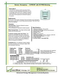
TC1 Series______________________________________<br />
<strong>Ameristar</strong> <strong>Energy</strong>, <strong>llc</strong><br />
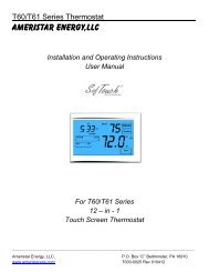
Installation and Operating Instructions<br />
For The TC1 Series Thermostat<br />
<strong>Ameristar</strong> <strong>Energy</strong>. P.O. Box “C” Bedminster, PA 18910<br />
www.ameristareps.com 7000-0010 rev. 120511
2 | P a g e<br />
Table of Contents<br />
Description Page number<br />
Overview 3<br />
Specification 3<br />
Installation and Mounting of TC1 Thermostat 4<br />
General Thermostat Operation 5<br />
System Wiring Diagrams 6<br />
Jumper Descriptions 8<br />
Remote Sensing 9<br />
Purge System Control 9<br />
Open Door and Window Monitoring 10<br />
Occupant Monitoring 10<br />
Diagnostic Monitoring Inputs 11<br />
Thermostat Configuration Setup Descriptions 13<br />
Thermostat Configuration Setup Mode 14<br />
Notes 18
3 | P a g e<br />
Overview<br />
The TC1 temperature control series is designed for 2 pipe, 4 pipe fan coil systems and heat pump<br />
systems. It is a precision temperature control series. It controls the HVAC system so room/building<br />
temperatures are precisely maintained. This series has diagnostic capabilities which will indicate when<br />
the HVAC system operation and efficiency levels are not performing at peak levels. When key<br />
components begin to fail or not perform properly, they are identified by LED indicators or LCD icon<br />
messages. If the equipment operation gets to a critical level all system operations will be shut down.<br />
Specifications<br />
Specifications:<br />
Set-point Temperature Range: 40⁰-90⁰F<br />
Comfort Limits: Adjustable Heat: 50⁰ - 90⁰F – Default 80⁰F<br />
Cool: 40⁰ - 80⁰F – Default 65⁰F<br />
Comfort Set Point: Adjustable 40⁰ - 90⁰F – Default 72⁰F<br />
Softstop (Unoccupied) Limits: Adjustable Heat: 40⁰ - 80⁰F – Default 50⁰F<br />
Cool: 50⁰ - 90⁰F – Default 85⁰F<br />
OFF Time Delay: Selectable Heat: 0 or 3 minutes – Default 0<br />
Cool: 0 or 3 minutes – Default 0<br />
Sample rate: Every 1 minute<br />
Accuracy: +/- 1⁰F<br />
Power Source: 24 VAC or 120-277 VAC<br />
Load Rating: Heat, Cool and Fan – 5 amps<br />
Diagnostic – 1 amps<br />
Fan Selection: HE/GAS – jumper selectable<br />
Fan Purge: Selectable 0, 1 or 2 minutes – Default 0<br />
Differential: Selectable 0.5⁰F, 1⁰F, 2⁰F or 3⁰F – Default 11)<br />
Room Temperature Offset: Selectable -5, -4, -3, -2, -1, 0, 1, 2, 3, 4 or 5 – Default 0<br />
Backlight: Selectable On/Off/Auto<br />
Room Temperature Display: Selectable On/Off<br />
Service Soon icon<br />
Service Now icon<br />
Fan Control Switch: On/Auto or Hi/Lo/Auto<br />
System Control Switch: Heat/Off/Cool or Heat/Off/Cool/Auto<br />
Stages: 1 Heat/ 1 Cool<br />
Case Color: White<br />
Storage Temperature Range: -35⁰ - 145⁰F
!<br />
4 | P a g e<br />
Installation and Mounting of TC1 Thermostat<br />
Caution – REMOVE POWER TO THE THERMOMOSTAT BEFORE<br />
DOING ANY WORK!<br />
Installation shall be done by a licensed electrician and/or licensed HVAC contractor. Installation and<br />
wiring shall adhere to all state, local and federal codes and requirements.<br />
1. Remove old thermostat cover and record wire terminations and colors below:<br />
Old Thermostat TC1 Thermostat<br />
Wire color terminations Description<br />
_____________ Black System Power Supply (L1 or 24vac)<br />
_____________ White Neutral or common<br />
_____________ Red Heat<br />
Blue Cool<br />
_____________ Green Lo Fan<br />
_____________ Yellow Hi Fan<br />
_____________ Orange Cooling reversing valve/damper<br />
_____________ Brown Heating reversing valve/damper<br />
_____________ Violet Purge<br />
2. Remove old thermostat from the wall.<br />
3. Remove the TC1 thermostat cover by placing a small flat head screw driver in the slot on the top<br />
of the thermostat. Gently pull the screw driver forward until the thermostat base separates from<br />
the cover (see Fig. 1).<br />
Fig. 1<br />
4. For new installation, locate the desired position for the thermostat. Do NOT mount on outside<br />
wall! Mounting location should be approximately 5 feet from the floor and away from any supply<br />
and return ducts. Mark mounting holes and wire holes (see Fig.2). Run wire from HVAC unit as<br />
needed.
5 | P a g e<br />
Fig. 2<br />
5. Mount the base plate using the hardware provided (drywall anchor and/or screws).<br />
Caution:<br />
If mounting 120 -277 vac thermostat, the unit must be mounted on a junction box!<br />
6. Connect the wires from the HVAC equipment to the thermostat wires using wire nuts. Consult<br />
wiring information above when retro fitting or HVAC manual for new installation.<br />
7. Push any extra wire back into the wall/junction box.<br />
8. Place the jumpers on the thermostat module in the appropriate location (reference Jumper<br />
Descriptions section).<br />
9. Align thermostat cover over the base and gently push until cover snaps into place.<br />
10. Thermostat is ready to be programmed then tested (reference Thermostat Configuration Setup<br />
section).<br />
1. Set point adjustment:<br />
General Thermostat Operation<br />
The room temperature set point is adjusted by pressing the UP button ( ) and/or DOWN button<br />
( )<br />
2. Fan Switch (Fan selection will differ based on model type):<br />
Auto: The fan will cycle with the heating and cooling system.<br />
The low fan will run when the room temperature drops 1⁰ below set point or rises 1⁰ above<br />
set point. If the room temperature continues to drop or rise 4⁰F below or above set point,<br />
the low fan will turn off and the high fan will turn on.<br />
Hi: The high fan will run continuously<br />
Med: The medium fan will run continuously<br />
Lo: The low fan will run continuously
3. System Switch (System selection will differ based on model type):<br />
6 | P a g e<br />
Heat: In the heat mode, heating will only activate.<br />
Off: Heating and cooling are turned off.<br />
Cool: In the cool mode, cooling will only activate.<br />
Auto: In the auto mode, the thermostat will automatically activate heating and cooling as needed<br />
to keep the room at the designated set point.<br />
4. Temperature display (⁰F/⁰C):<br />
Press the ⁰F/⁰C button to switch display between Fahrenheit and Celsius.<br />
5. Display set point only or room temperature and set point:<br />
The thermostat factory default setting is for set point only.<br />
To display room temperature and set point, press the UP and DOWN button together for 3<br />
seconds. The room temperature will be displayed.<br />
When the UP or DOWN button is pressed, the set point will be displayed for 5 seconds, then the<br />
display will return to room temperature.<br />
To display set point only, press the UP and DOWN button together for 3 seconds. Only the set<br />
point will be displayed.<br />
6. To access configuration set up mode:<br />
Press the UP button ( ) and ⁰F/⁰C button together for 10 seconds. Reference Configuration set<br />
up section for set up details.<br />
1. Typical 4 pipe fan coil wiring diagram<br />
System Wiring Diagrams
2. Typical 2 pipe fan coil wiring diagram<br />
7 | P a g e<br />
Note:<br />
JP2 jumper must be ON and water supply sensor (SDT-10) or “aquastat” must be<br />
connected to pin #1 and #5 as shown below:<br />
(Resistors provided)<br />
3. Typical heat pump wiring diagram
4. 4 pipe fan coil wiring diagram when retrofitting a thermostat with 3 speed fan and no common<br />
wire<br />
1. Remote Sensing Jumper (JP1):<br />
8 | P a g e<br />
Jumper Descriptions<br />
When the JP1 jumper is ON, the internal thermistor is used for sensing room temperature.<br />
When the JP1 jumper is OFF, remote sensor must be connected between connector pin #1 and<br />
2.<br />
2. Fan Coil System Jumper (JP2):<br />
When the JP2 jumper is ON, the thermostat is configured to operate a 2 pipe fan coil system.<br />
When the JP2 jumper is OFF, the thermostat is configured to operate a 4 pipe fan coil system or<br />
heat pump system.<br />
3. Gas/Electric Jumper (JP3):<br />
When the JP3 jumper is ON, the thermostat is configured for a GAS system. When the fan<br />
switch is in the AUTO position, the fan will NOT cycle with heating system, the fan will cycle with<br />
cooling system.<br />
When the JP3 jumper is OFF, the thermostat is configured for an ELECTRIC system. When the<br />
fan switch is in the AUTO position, the fan will cycle with both the heating and cooling system.<br />
4. Continuous fan jumper (JP5) – For TC1-xxx22 models only:<br />
When the JP5 jumper is ON, the fan will run continuously.<br />
When the JP5 jumper is OFF, the fan will cycle with the heating and cooling system.
9 | P a g e<br />
Remote Sensing<br />
The TC1 is equipped with remote sensing capability. When locating the remote sensor, choose a<br />
location that is not in directly exposure to the sun, near open windows, on an outside wall, or any<br />
location that may possibly provide an inaccurate room temperature reading.<br />
There are two types of remote sensors (purchased separately) that can be mounted up to 50ft away.<br />
1. Duct mount type, SDT-10, for installation in return air duct, etc.<br />
2. Wall mount type, SWT-10, for mounting on walls (not recommended for outdoor use).<br />
Installation:<br />
1. Mount the remote sensor following the instructions in the box.<br />
2. Connect the two wires from the remote sensor to thermostat connector terminal pins #1 and #2.<br />
3. Remove jumper JP1.<br />
4. Turn power to the thermostat ON.<br />
5. Wait for the control to display SETPOINT.<br />
6. Press the UP and DOWN buttons for 3 seconds. The thermostat will display room temperature.<br />
If only dashes or 88.88 are displayed, check that remote sensor wires are properly connected and<br />
that the wires are not damaged or cut.<br />
7. Apply low heat (hand) to the remote sensor.<br />
8. The room temperature displayed will show an increase in temperature.<br />
Purge System Control<br />
The TC1 thermostat will provide a 24vac or 120- 277vac output (depending on the thermostat model)<br />
for a purge system. The purge time is program selectable from 0 to 60 minutes in 1 minute<br />
increments (default = 0). The purge will turn ON every 60 minutes for the selected time period. If 0<br />
minutes is selected, the purge will never turn on. If 60 minutes is selected, the purge will run<br />
continuously. When the purge is ON, the LCD will display the “PURGE” icon and the DAMPER LED<br />
(under front diagnostics panel) will light.
10 | P a g e<br />
Open Door or Window Monitoring<br />
The TC1 thermostat is designed to work with devices that monitor open doors or windows.<br />
Connect a sensor (dry contacts) between connector pin #6 and #7 in the thermostat.<br />
When the sensor contacts are OPENED, the thermostat will operate normally.<br />
When the sensor contacts are CLOSED (SHORTED), the thermostat will turn OFF the heating or<br />
cooling system and display “OPEN DOOR” on the LCD display.<br />
When the sensor contacts are OPENED, the thermostat will resume normal operation.<br />
Occupant Monitoring<br />
The TC1 thermostat is designed to work with energy management device (motion sensor, front desk<br />
control, etc) that sense when the room is empty or occupied.<br />
The thermostat can be programmed with un-occupied set points for both heating and cooling (see<br />
Thermostat Configuration Setup Steps section steps 3 and 4). The un-occupied heat and cool set point<br />
range is 40⁰ - 90⁰F. Heat factory default = 65⁰F, Cool factory default = 85⁰F.<br />
Connect the energy management device (dry contacts) to connector pins #6 and #9.<br />
When the device contacts are OPENED, the thermostat will operate normally.<br />
When the device contacts are CLOSED (SHORTED), the thermostat will control at the “un-occupied” set<br />
point and display “UN-OCCUPIED” on the LCD display.<br />
When the device contacts are OPENED, the thermostat will operate normally.
1. Filter Monitor:<br />
11 | P a g e<br />
Diagnostic Monitoring Inputs<br />
The TC1 thermostat is designed work with filter monitoring devices with dry contact outputs.<br />
Connect the filter monitor device outputs to connect pins #6 and #12.<br />
When the filter monitor device contacts are OPENED, the thermostat will operate normally.<br />
When the filter monitor device contacts are CLOSED (SHORTED), the thermostat FILTER LED<br />
(under front diagnostics panel) will light. The thermostat continues to operate normally.<br />
When the filter monitor device contacts are OPENED, the thermostat FILTER LED will turn OFF.<br />
2. Fan or Motor Monitor:<br />
The TC1 thermostat is designed work with fan or motor monitoring device with dry contact<br />
outputs.<br />
Connect the fan or motor monitor device outputs to connect pins #6 and #8.<br />
When the fan or motor monitor device contacts are OPENED, the thermostat will operate<br />
normally.<br />
When the fan or motor monitor device contacts are CLOSED (SHORTED), the thermostat FAN<br />
LED (under the front diagnostic panel) will light. The thermostat turns all outputs off and the<br />
SERVICE NOW icon is displayed on the LCD.<br />
When the fan or motor monitor device contacts are OPENED, the thermostat FAN LED will turn<br />
OFF and the thermostat will operate normally.<br />
3. Service Soon indicator:
12 | P a g e<br />
When connector pin #6 and #10 are CLOSED (SHORTED), the SERVICE SOON icon is<br />
displayed on the LCD. The thermostat continues to operate normally.<br />
When connector pin #6 and #10 are OPENED, the SERVICE SOON icon is removed from the<br />
LCD display.<br />
4. Service Now indicator:<br />
When connector pin #6 and #11 are CLOSED (SHORTED), the SERVICE NOW icon is displayed<br />
on the LCD display and the thermostat will turn OFF all outputs.<br />
When connector pin #6 and #11 are OPENED, the SERVICE NOW icon is removed from the<br />
display and the thermostat will operate normally.<br />
5. Heat and Cool Air/Water Supply Monitoring:<br />
Supply temperatures can easily be monitored from this thermostat. By monitoring the supply<br />
temperatures, one can determine whether or not the system is operating at an efficient level.<br />
Installation and operation:<br />
1. Remove power to the thermostat.<br />
2. Connect the heat supply sensor (10k thermistor) to connector pins #1 and #3<br />
3. Connect the cool supply sensor (10k thermistor) to connector pins #1 and #4.<br />
4. Apply power to the thermostat.<br />
5. Wait for the LCD to display the room set point.<br />
6. Open the diagnostic panel on the front of the thermostat.<br />
7. Press the button next to the word HEAT. The LCD will display the temperature sensed by the<br />
heat supply sensor.<br />
8. Press the button next to the word COOL. The LCD will display the temperature sensed by the<br />
cool supply sensor.<br />
If dashes (- - . -) or er.r are displayed, either a 10k sensor is not being used or the wiring is<br />
incorrect. Check the connections at the connector and the sensor wiring for any nicks or cuts.<br />
Heat Hi temperature set point and Cool Lo temperature set point can be selected for the air/water<br />
supply during the thermostat configuration setup (see Thermostat Configuration Setup Mode<br />
section steps 10 and 11).<br />
When the sensor connected to connect pin #1 and #3 senses the air/water supply has reached<br />
the heat hi temperature set point, the HEAT LED under the diagnostic panel on the front of the<br />
thermostat will light. When the air/water temperature drops below the heat hi temperature set<br />
point, the HEAT LED will turn off.
13 | P a g e<br />
When the sensor connected to connector pins #1 and #4 senses the air/water supply has<br />
reached the cool lo temperature set point, the COOL LED under the diagnostic panel on the front<br />
of the thermostat will light. When the air/water supply rises above the cool lo temperature set<br />
point, the COOL LED will turn off.<br />
Thermostat Configuration Setup Descriptions<br />
1. Heat comfort limit:<br />
This function limits the thermostat from heating the room to extremely high temperatures.<br />
Factory default setting is 80⁰F. Programming range is 50⁰F to 90⁰F.<br />
2. Cool comfort limit:<br />
This function limits the thermostat from cooling the room to extremely low temperatures.<br />
Factory default setting is 65⁰F. Programming range is 40⁰F to 80⁰F. The Cool comfort limit must<br />
be at least 4 degrees below the heat comfort limit. If the cool comfort limit is not at least 4<br />
degrees below the heat comfort limit, the program will automatically change the heat comfort limit<br />
set point to 4 degrees above the cool limit set point when the configuration setup is saved.<br />
3. Comfort setting:<br />
The thermostat can be programmed to start at a specific set point every time the thermostat is<br />
turned on or the system switch is moved between heat, off, cool and auto.<br />
Factory default setting is 72⁰F. Programming range is 40⁰F to 90⁰F<br />
4. Un-occupied set points:<br />
These set points are used when there is an occupancy sensing device connected to pins #6 and<br />
#9 in the thermostat. When pins #6 and #9 are closed (shorted), the thermostat will be placed in<br />
the un-occupied mode. The un-occupied icon will be displayed and the thermostat will control at<br />
the heat un-occupied set point (default = 50⁰F) and/or cool un-occupied set point (default = 85⁰F)<br />
depending on SYSTEM button setting. When pins #6 and #9 are opened (occupants sensed),<br />
the thermostat will return to controlling at the previous set point prior to going into the un-occupied<br />
mode. The cool un-occupied set point must be at least 4 degrees above the heat un-occupied set<br />
point. If the cool un-occupied set point is not at least 4 degrees above the heat un-occupied set<br />
point, the program will automatically change the heat un-occupied set point to 4 degrees below<br />
the cool un-occupied set point when the configuration setup is saved.<br />
5. Cool off time delay:<br />
This time delay is to protect against compressor short cycling and to prolong the HVAC<br />
equipment life.<br />
The default value is 0 minutes. The cool off time delay is program selectable between 0 and 3<br />
minutes.<br />
6. Heat off time delay:<br />
This time delay is to protect against compressor short cycling and to prolong the HVAC<br />
equipment life.<br />
The factory default is 0 minutes. The heat off time delay is program selectable between 0 and 3<br />
minutes.<br />
7. Fan purge:
The fan will continue to run for the program selected period of time to purge latent cool or heat<br />
from the system.<br />
The factory default is 0. Programming range is 0 – 2 minutes in 1 minute increments.<br />
8. Differential:<br />
The differential is the temperature difference between when the heat/cool system turns ON and<br />
when the heat/cool system turn OFF.<br />
9. Key locking:<br />
When this feature is activated by selecting key off, the room set point will be locked at the<br />
temperature set prior to entering configuration setup mode and selecting key off. When the<br />
SYSTEM switch is moved between heat, off, cool and auto, the set point will be locked at the<br />
comfort set point. Pushing the up and down button will do nothing. The end user will not be able<br />
to change the set point.<br />
To Enter Configuration Setup Mode:<br />
14 | P a g e<br />
Thermostat Configuration Set Up Mode<br />
1. Press Up and ⁰F/⁰C button together for 10 seconds.<br />
Heat Comfort Limit:<br />
2. The LCD will display PROG, HEAT and LIMIT 80.0⁰F<br />
3. Press the UP or DOWN button to set the desired heat comfort limit.<br />
4. Press the ⁰F/⁰C button<br />
Cool Comfort Limit:<br />
5. The LCD will display PROG, COOL and LIMIT 65⁰F<br />
6. Press the UP or DOWN button to set the desired cool comfort limit.<br />
7. Press the ⁰F/⁰C button<br />
Comfort Set Point:<br />
8. The LCD will display PROG SET PT and 72⁰F<br />
9. Press the UP or DOWN button to set the desired comfort set point (40⁰F to 90⁰F)<br />
10. Press the ⁰F/⁰C button<br />
Heat softstop (Unoccupied) set point:
15 | P a g e<br />
11. The LCD will display PROG, HEAT UNOCCUPIED and 50⁰F<br />
12. Press the UP or DOWN button to set the desired heat softstop set point (40⁰F to 90⁰F)<br />
13. Press the ⁰F/⁰C button<br />
Cool softstop (Un-occupied) set point:<br />
14. The LCD will display PROG, COOL UNOCCUPIED and 85⁰F<br />
15. Press the UP or DOWN button to set the desired cool softstop set point (40⁰F to 90⁰F)<br />
16. Press the ⁰F/⁰C button<br />
Heat off time delay:<br />
17. The LCD will display PROG, HEAT, DELAY, 0 min<br />
18. Press the UP or DOWN button to select 0 min or 3 min heat off delay<br />
19. Press the ⁰F/⁰C button<br />
Cool off time delay:<br />
20. The LCD will display PROG, COOL, DELAY, 0 min<br />
21. Press the UP or DOWN button to select 0 min or 3 min cool off delay<br />
22. Press the ⁰F/⁰C button<br />
Fan Purge:<br />
23. The LCD will display PROG, FAN and 0 min<br />
24. Press the UP or DOWN button to select 0, 1, or 2 min fan purge time<br />
25. Press the ⁰F/⁰C button<br />
Differential<br />
26. The LCD will display PROG DIFF and 1<br />
27. Press the UP or DOWN button to select 0.5, 1, 2, or 3 degrees for the differential<br />
28. Press the ⁰F/⁰C button<br />
Room temperature offset:
16 | P a g e<br />
29. The LCD will display PROG, OFFSET and 0<br />
30. Press the UP or DOWN button to select -5, -4, -3, -2, -1, 0, 1, 2, 3, 4, or 5 degrees for the<br />
room temperature offset<br />
31. Press the ⁰F/⁰C button<br />
Heat supply Hi temperature set point:<br />
32. The LCD will display PROG, HEAT, HI and 90<br />
33. Press the UP or DOWN button to select the heat supply hi temperature set point (range 40⁰F<br />
to 150⁰ F)<br />
34. Press the ⁰F/⁰C button<br />
Cool supply Lo temperature set point:<br />
35. The LCD will display PROG, COOL, LO and 60<br />
36. Press the UP or DOWN button to select the cool supply lo temperature set point (range 40⁰F<br />
to 150⁰ F)<br />
37. Press the ⁰F/⁰C button<br />
System purge or fresh air damper:<br />
38. The LCD will display PURGE and 03<br />
39. Press the UP or DOWN button to select the purge time (range 0 to 60 min in increments of 1<br />
minute)<br />
40. Press the ⁰F/⁰C button<br />
Back light setting:<br />
41. The LCD will display PROG, BACK LIGHT and AUTO<br />
42. Press the UP or DOWN button to select ON, OFF or AUTO<br />
43. Press the ⁰F/⁰C button<br />
Key locking setting:<br />
44. The LCD will display PROG, KEY and ON
17 | P a g e<br />
45. Press the UP or DOWN button to select ON or OFF<br />
46. Press the ⁰F/⁰C button<br />
Save program:<br />
47. The LCD will display PROG and SAVE<br />
48. Press the ⁰F/⁰C button<br />
49. The settings will be saved and the thermostat will resume normal operation.<br />
Limited Warranty:<br />
The TC1 Control has been designed to operate as a standalone thermostat or part of an energy<br />
management system.<br />
This control is warranted for a period of 2 years against any workmanship, performance defects, etc.<br />
The only responsibility that <strong>Ameristar</strong> <strong>Energy</strong> will assume is to repair or provide a replacement based<br />
upon CAS’s discretion.<br />
<strong>Ameristar</strong> does not assume any other liability.<br />
Technical assistance:<br />
<strong>Ameristar</strong> <strong>Energy</strong>, LLC has many years of experience in the operation and performance of HVAC/R<br />
systems, energy efficiency and system longevity and customer satisfaction. If you need any assistance<br />
in the installation or function of this control call:<br />
Technical Service Group<br />
1-800-227-7727
18 | P a g e<br />
Notes<br />
ON Intentionally<br />
Left Blank