Controlled Air Systems, Inc.
Controlled Air Systems, Inc.
Controlled Air Systems, Inc.

You also want an ePaper? Increase the reach of your titles
YUMPU automatically turns print PDFs into web optimized ePapers that Google loves.
T55 Series_______________________________________<br />
<strong>Controlled</strong> <strong>Air</strong> <strong>Systems</strong>, <strong>Inc</strong>.<br />
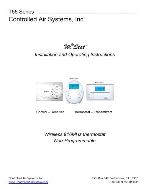
Installation and Operating Instructions<br />
Control – Receiver Thermostat – Transmitters<br />
Wireless 916MHz thermostat<br />
Non-Programmable<br />
<strong>Controlled</strong> <strong>Air</strong> <strong>Systems</strong>, <strong>Inc</strong>. P.O. Box 347 Bedminster, PA 18910<br />
www.<strong>Controlled</strong><strong>Air</strong>System.com 7000-0009 rev. 011511
2 | P a g e<br />
Table of Contents<br />
Description Page number<br />
Overview 3<br />
Specifications 3<br />
Control-receiver mounting and installation 4<br />
Control-receiver testing 6<br />
Selecting Thermostat-transmitter location 8<br />
Establishing communication between thermostat-transmitter and control-receiver 8<br />
Thermostat mounting and installation 9<br />
Switch settings 10<br />
Configuring thermostat<br />
A. Differential set up 10<br />
B. Comfort limits 10<br />
Jumpers 11<br />
System testing 11<br />
Wiring diagrams 13
3 | P a g e<br />
Overview<br />
The T55 series wireless non-programmable thermostat is a two stage heat and two stage cool<br />
thermostat. The wireless system is made up of two components:<br />
1. Thermostat-Transmitter:<br />
Displays room temperature, system mode, time of day, and maintains the programming<br />
events. The thermostat-transmitter senses the room temperature and sends a pre-coded<br />
signal to the receiver. The signal will transmit up to 150 ft in open space*.<br />
2. Control- Receiver :<br />
Continuously looks for the coded signal sent from the thermostat-transmitter. The controlreceiver<br />
is wired to the heating and cooling system. It can be mounted external from the<br />
system or at the location of the old thermostat. The control has indicator LED’s that show<br />
systems operation.<br />
*Non-disclaimer:<br />
Wireless communication may not be appropriate for all applications. Transmitter signal strength can be affected by<br />
multiple mediums (metal, wood, etc.). Optimal placement of the thermostat and receiver needs to be achieved by<br />
minimizing the distance and number of mediums (walls, ceilings, etc) between the units. Only the highest grade of<br />
batteries should be used since as the battery voltage decreases, so does the signal strength.<br />
Specifications<br />
1. Switch type: Push button<br />
2. System switch: Heat/Off/AC or Heat/Off/AC/Auto<br />
3. Fan switch: Auto/On<br />
4. Transmitting frequency: 916MHz<br />
5. RF signal is sent every 5 minutes<br />
6. Transmitting distance: 150 ft. open space, approximately 50 ft with wall<br />
7. Meets FCC part 15 rules<br />
8. Input voltage:<br />
a. Thermostat-Transmitter – 2 “AA” batteries<br />
b. Control-Receiver – 24vac +/- 10%<br />
9. Receiver Power consumption: 1.5VA<br />
10. Load rating: 1A@24vac<br />
11. Thermostat temperature range: 32⁰F to 99⁰F<br />
12. Set point range: 44⁰ to 95⁰F<br />
13. Accuracy: +/- 1⁰F<br />
14. Differential: selectable 0.5, 1.0, 2.0 and 3.0⁰F<br />
15. Comfort limits<br />
16. Temperature sensing: internal<br />
17. LCD back light
i<br />
4 | P a g e<br />
Control-Receiver Mounting and Installation<br />
Remove power to the thermostat before doing any work! Installations shall be done by a<br />
licensed electrician and/or licensed HVAC contractor. Installation and wiring shall adhere<br />
to all state, local and federal codes and requirements.<br />
1. Remove old thermostat cover and record wire terminations and colors below. If new installation,<br />
skip to step #3.<br />
Old Thermostat T55 Control-Receiver<br />
Wire color Terminations Description<br />
____________________ RC 24vac cooling<br />
____________________ Rh 24vac heating<br />
____________________ C Common<br />
____________________ Y 1 st stage Cooling<br />
____________________ Y2 2 nd stage Cooling<br />
____________________ O Cooling damper/reversing valve<br />
____________________ W 1 st stage Heating<br />
____________________ W2 2 nd stage Heating<br />
____________________ B Heating damper/reversing valve<br />
____________________ G Fan<br />
2. Remove old thermostat<br />
3. The control-receiver can be mounted either at the old thermostat location or at the HVAC unit.<br />
Do not locate control-receiver inside any metal enclosures.<br />
4. To mount the control-receiver, loosen bottom two screws until the top can be removed (see Fig<br />
1).
Fig. 1<br />
5. Remove control-receiver cover.<br />
6. Place the control-receiver at the desired mounting location and mark the mounting and wire holes<br />
(see Fig. 2).<br />
5 | P a g e<br />
Fig. 2<br />
7. Drill the mounting holes and insert the plastic anchors (supplied)<br />
8. Pull the HVAC wires through the wiring hole and align the control-receiver over the mounting<br />
holes. Using the supplied screws, screw the control-receiver to the wall.<br />
9. Connect the HVAC wires to the control-receiver terminals as recorded in step #1 or per the HVAC<br />
manual if new installation.<br />
10. Before replacing the front cover of the control-receiver, confirm the ELEC/GAS switch (see Fig.2)<br />
is in the correct location (reference “Switch setting” section).<br />
11. Align the top plastic hooks on the control-receiver cover with the indentations on the top of the<br />
control-receiver base and gently push cover onto base and tighten screws on the bottom (see<br />
Fig. 3).<br />
Fig. 3<br />
.
6 | P a g e<br />
Control-Receiver Testing<br />
After the control-receiver has been mounted and wired to the HVAC system, turn the power ON to the<br />
HVAC system and test as follows:<br />
1. Press and hold the “PROG” button until the LEARN LED lights<br />
2. Press the “FAN” button once. The FAN LED will light and the HVAC fan will turn ON.<br />
3. Press the “FAN” button again. The FAN LED and HVAC fan will turn OFF.<br />
4. Press the “FAN” button again. The FAN LED and HVAC fan will turn ON.<br />
5. Press the “SYSTEM” button once, the COOL LED will light. HVAC cooling system is OFF, Fan is<br />
still running.<br />
6. Press the “PROG” button once, the HVAC cooling system will turn ON.<br />
7. Press the “SYSTEM” button once, the COOL LED and HVAC cooling system will turn OFF and<br />
the HEAT LED will light, fan will still be ON.
8. Press the “PROG” button once, the HVAC heating system will turn ON.<br />
9. Press the “PROG” button once, the HVAC heating system will turn OFF, fan will continue to run.<br />
10. Press the “SYSTEM” button once, the HEAT LED will turn OFF.<br />
11. Press the “FAN” button once, the FAN LED AND HVAC fan will turn OFF.<br />
12. Press and hold the “PROG” button until the LEARN LED turns OFF.<br />
13. The control-receiver testing is complete. Select an appropriate locaton for the thermostattransmitter<br />
(see Selecting Thermostat-Transmitter Location section).<br />
7 | P a g e
8 | P a g e<br />
Selecting Thermostat-Transmitter Location<br />
Before permanently mounting the thermostat, verify communication between the control-receiver and<br />
thermostat-transmitter.<br />
The best placement for the thermostat is in a location that has direct line of sight with the controlreceiver.<br />
The RF signal used for communication is strongest when there is nothing between the two units, no<br />
walls, floors, etc. With each medium that is added between the two units, the RF signal will start to<br />
degrade. How much the signal degrades depends on the medium. Metal and water have the highest<br />
value of degradation followed by plaster walls that have metal mesh and insulation with metallic film.<br />
Once the desired thermostat location is selected, establish communication between the thermostat and<br />
control-receiver as outlined in the “Establishing Communication between Thermostat-transmitter and<br />
Control-receiver” section. Intermittent communication or no communication means that a better<br />
thermostat location needs to be selected. The thermostat and controller should to be moved closer<br />
together with a better line of sight.<br />
Battery power is also critical to reliable communication between the two units. The highest quality<br />
batteries should be used. As the battery voltage drops, the signal strength drops. If the low battery icon<br />
is display, change the batteries immediately.<br />
Establishing Communication between Thermostat-transmitter and Control-receiver<br />
Batteries must be placed in the thermostat-receiver before any thermostat set up, configuring or<br />
testing can be done!<br />
1. Turn power on to the HVAC system.<br />
2. Press and hold the “SYSTEM” button on the control-receiver until the LEARN LED blinks.<br />
3. Press the SYSTEM button on the thermostat-transmitter until the LEARN LED on the controlreceiver<br />
stops blinking and turns OFF (approximately 15 seconds).
4. Communication has been established.<br />
5. To confirm communication has been established, complete the following step:<br />
9 | P a g e<br />
a. Press the SYSTEM button on the thermostat-transmitter until the SYSTEM OFF icon is<br />
displayed.<br />
b. Press the FAN button on the thermostat-receiver once. The FAN AUTO icon on the<br />
thermostat will change to display FAN and the HVAC fan will turn ON.<br />
c. Press the FAN button on the thermostat-receiver again. The FAN AUTO icon will be<br />
displayed and the HVAC fan will turn OFF<br />
Thermostat Mounting and Installation<br />
Important:<br />
Before permanently mounting thermostat, make sure communication testing has been<br />
completed (see “Establishing Communication between Thermostat-transmitter and<br />
Control-receiver” section)!<br />
1. Remove thermostat back plate by inserting a flat head screw driver in the groove at the center top<br />
of the thermostat (see Fig.14) and gently push back (see Fig. 15).<br />
Fig. 14 Fig. 15<br />
2. Place the thermostat back plate at the desired mounting location. Thermostat should be mounted<br />
about 5 feet off the floor and away from any supply or return ducts.<br />
3. Mark mounting holes.<br />
4. Drill the mounting holes and insert the plastic anchors (supplied)<br />
5. Align the thermostat back plate with the mounting holes. Using the supplied screws, screw the<br />
back plate to the wall.<br />
6. Align the indentations in the front cover with the mounting nubs on the back plate. Gently press<br />
the front cover against the back plate until the thermostat snaps together.<br />
7. Unit is ready to be programmed and tested.
1. GAS/ELEC slide switch:<br />
10 | P a g e<br />
Switch Settings<br />
When slide switch is placed in the GAS position, the fan will cycle with cooling only.<br />
When slide switch is placed in the ELEC position, the fan will cycle with heating and cooling.<br />
Configuring Thermostat<br />
Batteries must be placed in the thermostat-receiver before any thermostat set up, programming<br />
or testing can be done!<br />
A. Differential set up (see Fig. 6):<br />
Fig 6<br />
1. Press the SYSTEM button until OFF is displayed.<br />
2. Press and HOLD the UP (+) and DOWN (-) button for 5 seconds, the LCD will display 1.0<br />
(default value)<br />
3. Press the + or – button to select between 0.5, 1.0, 2.0 or 3.0<br />
4. Wait 10 seconds, the setting will be saved and the thermostat will return to normal operation.<br />
The differential is the number of degrees between the turn on and turn off points<br />
B. Comfort limit set up (see Fig. 6)<br />
Comfort limits prevent occupants from heating or cooling a room to extreme temperatures. Once<br />
the comfort limits are selected, the heat set points will only be able to be set from 40 to the heat<br />
comfort limit and the cool set points will only be able to be set from 90 to the cool comfort limit.<br />
Example:<br />
Heat comfort limit is set at 76 degree F<br />
Cool comfort limit is set at 70 degree F<br />
When the thermostat is in the A/C mode and the + or – button is press to change the cool set<br />
point, the set point range will be 90 – 70 degree F<br />
When the thermostat is in the HEAT mode and the + or – button is press to change the cool set<br />
point, the set point range will be 40-76 degree F
11 | P a g e<br />
Setting the cool and heat comfort limits:<br />
1. Press SYSTEM button until A/C is displayed.<br />
2. Press and HOLD the UP (+) and DOWN (-) button for 5 seconds, the LCD will display 60.0<br />
(default value)<br />
3. Press the + or – button to set the cool comfort limit to the desired temperature<br />
4. Wait 10 seconds, the setting will be saved and the thermostat will return to normal operation.<br />
5. Press the SYSTEM twice HEAT will be displayed<br />
6. Press and HOLD the UP (+) and DOWN (-) button for 5 seconds, the LCD will display 90.0<br />
(default value)<br />
7. Press the + or – button to set the cool comfort limit to the desired temperature<br />
8. Wait 10 seconds, the setting will be saved and the thermostat will return to normal operation.<br />
1. F/C Jumper:<br />
2. Delay Jumper:<br />
Fan Testing:<br />
Jumpers<br />
0 – When the F/C jumper is in the “0” position, the thermostat temperature displays in<br />
Celsius<br />
1 – When the F/C jumper is in the “1” position, the thermostat temperature displays in<br />
Fahrenheit<br />
ON – When the Delay jumper is in the ON position, there is a 3 minute off delay for both<br />
heating and cooling<br />
OFF – When the Delay jumper is in the OFF position, there is no off delay for heating and<br />
cooling<br />
System Testing<br />
1. Press the SYSTEM button until the LCD displays SYSTEM OFF.<br />
2. Press the FAN button until the LCD displays FAN, the HVAC fan will turn ON.<br />
3. Press the FAN button until the LCD displays FAN AUTO, the HVAC fan will turn OFF.
12 | P a g e<br />
Heat Testing:<br />
1. Press the SYSTEM button until the LCD displays HEAT<br />
2. Press the FAN button until the LCD displays FAN AUTO<br />
3. Press the + button until the set point is at least 5 degrees above room temperature.<br />
4. The HVAC heating system will turn ON (if the OFF delay is ON, it may take up to 3 minutes for<br />
heating to turn ON).<br />
5. Press the – button until the set point is at least 5 degrees below room temperature.<br />
6. The HVAC heating system will turn OFF.<br />
Cooling Testing:<br />
1. Press the SYSTEM button until the LCD displays A/C<br />
2. Press the FAN button until the LCD displays FAN AUTO<br />
3. Press the – button until the set point is at least 5 degrees below room temperature.<br />
4. The HVAC cooling system will turn ON (if the OFF delay is ON, it may take up to 3 minutes for<br />
the cooling system to turn ON).<br />
5. Press the + button until the set point is at least 5 degrees above room temperature.<br />
6. The HVAC cooling system will turn OFF.<br />
Auto Testing:<br />
1. Press the FAN button until the LCD displays FAN AUTO<br />
2. Press the SYSTEM button until the LCD displays HEAT<br />
3. Press the UP (+) or DOWN (-) button to set the TARGET set point to 2 degrees above room<br />
temperature<br />
4. Wait 10 seconds for the thermostat to return to normal operating mode<br />
5. Press the SYSTEM button until the LCD displays A/C<br />
6. Press the UP (+) or DOWN (-) button to set the TARGET set point to 5 degrees above room<br />
temperature<br />
7. Wait 10 seconds for the thermostat to return to normal operating mode<br />
8. Press the SYSTEM button ONCE to place the thermostat in AUTO mode AUTO icon is solid,<br />
FAN icon flashes.<br />
9. The heat will turn ON as soon as the thermostat is placed in the AUTO mode (unless the 3<br />
minute on delay is selected then it could take up to 3 minutes to turn on)<br />
10. To force cooling ON, the room must be warmed to at least 6 degrees above room temperature<br />
or a heating device such as a heat gun or hair dryer can be used to warm the upper left corner<br />
of the thermostat to warm the temperature around the thermistor.<br />
11. When the temperature rises 1 degree above the cool set point the cooling will turn ON.
1. Heat Pump System:<br />
2. Heat Pump System with Auxiliary Heat:<br />
13 | P a g e<br />
Wiring Diagrams<br />
Thermostat connections<br />
Thermostat connections
3. 2 Heat/ 2 Cool System:<br />
4. 2 Heat/ 2 Cool System 2 transformers:<br />
14 | P a g e<br />
Thermostat connections<br />
Thermostat connections
5. 1 Heat/ 1 Cool System:<br />
6. Heat only System:<br />
15 | P a g e<br />
Thermostat connections<br />
Thermostat connections
7. Cool only System:<br />
16 | P a g e<br />
Thermostat connections
17 | P a g e<br />
Notes<br />
Intentionally<br />
left blank