10-MHz Adjustable Photoreceivers
10-MHz Adjustable Photoreceivers
10-MHz Adjustable Photoreceivers
Create successful ePaper yourself
Turn your PDF publications into a flip-book with our unique Google optimized e-Paper software.
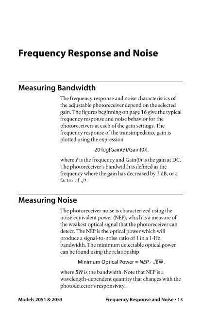
Frequency Response and Noise<br />
Measuring Bandwidth<br />
Measuring Noise<br />
The frequency response and noise characteristics of<br />
the adjustable photoreceiver depend on the selected<br />
gain. The figures beginning on page 16 give the typical<br />
frequency response and noise behavior for the<br />
photoreceivers at each of the gain settings. The<br />
frequency response of the transimpedance gain is<br />
plotted using the expression<br />
20·log[Gain(ƒ)/Gain(0)],<br />
where ƒ is the frequency and Gain(0) is the gain at DC.<br />
The photoreceiver’s bandwidth is defined as the<br />
frequency where the gain has decreased by 3 dB, or a<br />
factor of 2 .<br />
The photoreceiver noise is characterized using the<br />
noise equivalent power (NEP), which is a measure of<br />
the weakest optical signal that the photoreceiver can<br />
detect. The NEP is the optical power which will<br />
produce a signal-to-noise ratio of 1 in a 1-Hz<br />
bandwidth. The minimum detectable optical power<br />
can be found using the relationship<br />
Minimum Optical Power = NEP · BW<br />
,<br />
where BW is the bandwidth. Note that NEP is a<br />
wavelength-dependent quantity that changes with the<br />
photodetector’s responsivity.<br />
Models 2051 & 2053 Frequency Response and Noise 13


