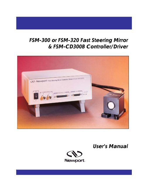
FSM-300 or FSM-320 Fast Steering Mirror & FSM-CD300B ...
FSM-300 or FSM-320 Fast Steering Mirror & FSM-CD300B ...
FSM-300 or FSM-320 Fast Steering Mirror & FSM-CD300B ...

You also want an ePaper? Increase the reach of your titles
YUMPU automatically turns print PDFs into web optimized ePapers that Google loves.
<strong>FSM</strong>-<strong>300</strong> <strong>or</strong> <strong>FSM</strong>-<strong>320</strong> <strong>Fast</strong> <strong>Steering</strong> Mirr<strong>or</strong><br />
& <strong>FSM</strong>-CD<strong>300</strong>B Controller/Driver<br />
User’s Manual
EU Declaration of Conf<strong>or</strong>mity 3<br />
EU Declaration of Conf<strong>or</strong>mity<br />
We declare that the accompanying product, identified with the mark,<br />
complies with requirements of the Electromagnetic Compatibility Directive,<br />
89/336/EEC and the Low Voltage Directive 73/23/EEC.<br />
Model Number: <strong>FSM</strong>-<strong>300</strong> <strong>or</strong> <strong>FSM</strong>-<strong>320</strong> & <strong>FSM</strong>-CD<strong>300</strong>B<br />
Year mark affixed: 2003<br />
Type of Equipment:<br />
Electrical equipment f<strong>or</strong> measurement, control and lab<strong>or</strong>at<strong>or</strong>y use.<br />
Standards Applied:<br />
Compliance was demonstrated to the following standards to the extent applicable:<br />
BS EN61326-1:1997+A1+A2 “Electrical equipment f<strong>or</strong> measurement, control<br />
and lab<strong>or</strong>at<strong>or</strong>y use – EMC requirements.”<br />
This equipment meets the CISPR 11 Class A Group 1 radiated and<br />
conducted emission limits.<br />
This equipment passed perf<strong>or</strong>mance criteria B f<strong>or</strong> RF immunity tests per<br />
BS EN 61000-4-3.<br />
BS EN 61000-3-2:2001, Harmonic current emissions, Class A.<br />
BS EN 61000-3-3:2002, Voltage fluctuations and flicker.<br />
BS EN 61010-1:1993, A1+A2 “Safety requirements f<strong>or</strong> electrical equipment f<strong>or</strong><br />
measurement, control and lab<strong>or</strong>at<strong>or</strong>y use.”<br />
Alain Danielo<br />
VP European Operations<br />
Zone Industrielle<br />
45340 Beaune-la-Rolande, France<br />
Dan Dunahay<br />
Direct<strong>or</strong> of Quality Systems<br />
1791 Deere Avenue<br />
Irvine, CA, USA
Warranty 4<br />
Warranty<br />
Newp<strong>or</strong>t C<strong>or</strong>p<strong>or</strong>ation warrants that this product will be free from defects in<br />
material and w<strong>or</strong>kmanship and will comply with Newp<strong>or</strong>t’s published specifications<br />
at the time of sale f<strong>or</strong> a period of one year from date of shipment.<br />
If found to be defective during the warranty period, then product will either<br />
be repaired <strong>or</strong> replaced at Newp<strong>or</strong>t's option.<br />
To exercise this warranty, write <strong>or</strong> call your local Newp<strong>or</strong>t office <strong>or</strong> representative,<br />
<strong>or</strong> contact Newp<strong>or</strong>t headquarters in Irvine, Calif<strong>or</strong>nia. You will<br />
be given prompt assistance and return instructions. Send the product, freight<br />
prepaid, to the indicated service facility. Repairs will be made and the<br />
instrument returned freight prepaid. Repaired products are warranted f<strong>or</strong> the<br />
remainder of the <strong>or</strong>iginal warranty period <strong>or</strong> 90 days, whichever first occurs.<br />
Limitation of Warranty<br />
The above warranties do not apply to products which have been repaired<br />
<strong>or</strong> modified without Newp<strong>or</strong>t’s written approval, <strong>or</strong> products subjected to<br />
unusual physical, thermal <strong>or</strong> electrical stress, improper installation, misuse,<br />
abuse, accident <strong>or</strong> negligence in use, st<strong>or</strong>age, transp<strong>or</strong>tation <strong>or</strong> handling.<br />
This warranty also does not apply to fuses, batteries, <strong>or</strong> damage from battery<br />
leakage.<br />
THIS WARRANTY IS IN LIEU OF ALL OTHER WARRANTIES, EXPRESSED OR<br />
IMPLIED, INCLUDING ANY IMPLIED WARRANTY OF MERCHANTABILITY<br />
OR FITNESS FOR A PARTICULAR USE. NEWPORT CORPORATION SHALL<br />
NOT BE LIABLE FOR ANY INDIRECT, SPECIAL, OR CONSEQUENTIAL<br />
DAMAGES RESULTING FROM THE PURCHASE OR USE OF ITS PRODUCTS.<br />
First printing 2003<br />
Copyright 2003 by Newp<strong>or</strong>t C<strong>or</strong>p<strong>or</strong>ation, Irvine, CA. All rights reserved.<br />
No part of this manual may be reproduced <strong>or</strong> copied without the pri<strong>or</strong> written<br />
approval of Newp<strong>or</strong>t C<strong>or</strong>p<strong>or</strong>ation.<br />
This manual has been provided f<strong>or</strong> inf<strong>or</strong>mation only and product specifications<br />
are subject to change without notice. Any change will be reflected in<br />
future printings.<br />
© 2003 Newp<strong>or</strong>t C<strong>or</strong>p<strong>or</strong>ation<br />
1791 Deere Ave.<br />
Irvine, CA 92606<br />
(949) 863-3144<br />
P/N 40342-01, Rev. C
5 Confidentiality & Proprietary Rights<br />
Confidentiality & Proprietary Rights<br />
Reservation of Title:<br />
The Newp<strong>or</strong>t Programs and all materials furnished <strong>or</strong> produced in connection with<br />
them ("Related Materials") contain trade secrets of Newp<strong>or</strong>t and are f<strong>or</strong> use only in<br />
the manner expressly permitted. Newp<strong>or</strong>t claims and reserves all rights and benefits<br />
aff<strong>or</strong>ded under law in the Programs provided by Newp<strong>or</strong>t C<strong>or</strong>p<strong>or</strong>ation.<br />
Newp<strong>or</strong>t shall retain full ownership of Intellectual Property Rights in and to all<br />
development, process, align <strong>or</strong> assembly technologies developed and other derivative<br />
w<strong>or</strong>k that may be developed by Newp<strong>or</strong>t. Customer shall not challenge, <strong>or</strong> cause any<br />
third party to challenge, the rights of Newp<strong>or</strong>t.<br />
Preservation of Secrecy and Confidentiality and Restrictions to Access:<br />
Customer shall protect the Newp<strong>or</strong>t Programs and Related Materials as trade secrets<br />
of Newp<strong>or</strong>t, and shall devote its best eff<strong>or</strong>ts to ensure that all its personnel protect<br />
the Newp<strong>or</strong>t Programs as trade secrets of Newp<strong>or</strong>t C<strong>or</strong>p<strong>or</strong>ation. Customer shall not<br />
at any time disclose Newp<strong>or</strong>t's trade secrets to any other person, firm, <strong>or</strong>ganization,<br />
<strong>or</strong> employee that does not need (consistent with Customer's right of use hereunder)<br />
to obtain access to the Newp<strong>or</strong>t Programs and Related Materials. These restrictions<br />
shall not apply to inf<strong>or</strong>mation (1) generally known to the public <strong>or</strong> obtainable from<br />
public sources; (2) readily apparent from the keyboard operations, visual display,<br />
<strong>or</strong> output rep<strong>or</strong>ts of the Programs; (3) previously in the possession of Customer <strong>or</strong><br />
subsequently developed <strong>or</strong> acquired without reliance on the Newp<strong>or</strong>t Programs; <strong>or</strong><br />
(4) approved by Newp<strong>or</strong>t f<strong>or</strong> release without restriction.
Table of Contents 6<br />
Table of Contents<br />
EU Declaration of Conf<strong>or</strong>mity............................................................... 3<br />
Warranty................................................................................................. 4<br />
Confidentiality & Proprietary Rights..................................................... 5<br />
Table of Contents ................................................................................... 6<br />
1. Safety Precautions.................................................................... 9<br />
1.1 General Safety Warnings.............................................................. 9<br />
1.2 General Cautions .......................................................................... 9<br />
2. <strong>Fast</strong> <strong>Steering</strong> Mirr<strong>or</strong> Technology........................................... 11<br />
3. Typical Specifications ............................................................ 15<br />
3.1 <strong>FSM</strong> System ............................................................................... 15<br />
3.2 Standard Mirr<strong>or</strong> Options............................................................. 16<br />
3.3 <strong>FSM</strong>-CD<strong>300</strong>B Controller/Driver................................................ 17<br />
3.4 Bode Plots................................................................................... 18<br />
3.5 Safe Operating Area ................................................................... 19<br />
4. Unpacking the <strong>FSM</strong>................................................................. 21<br />
4.1 Packing List................................................................................ 21<br />
4.2 Freeing the Mirr<strong>or</strong> Head............................................................. 21<br />
4.3 St<strong>or</strong>ing and Shipping the Mirr<strong>or</strong> Head ....................................... 22<br />
4.4 Replacing the Mirr<strong>or</strong> .................................................................. 22<br />
5. System Components .............................................................. 23<br />
5.1 <strong>FSM</strong> Mirr<strong>or</strong> Head Assembly...................................................... 23<br />
5.2 <strong>FSM</strong>-CD<strong>300</strong>B Controller/Driver................................................ 26<br />
5.3 <strong>FSM</strong> Electronics ......................................................................... 27<br />
5.4 <strong>FSM</strong>-CD<strong>300</strong>B Controller/Driver Cable Pin Connections.......... 28<br />
5.5 Interface I/O Pin Connections .................................................... 30<br />
6. System Operation ................................................................... 31<br />
6.1 Installation Location & Ventilation............................................ 31<br />
6.2 Electrical Connections................................................................ 31<br />
6.3 Command Inputs ........................................................................ 32<br />
6.4 Position Outputs ......................................................................... 33<br />
6.5 Fault Indication........................................................................... 33<br />
6.6 External Sens<strong>or</strong> Feedback Control Mode................................... 34<br />
6.7 Open Loop Control Mode .......................................................... 35<br />
6.8 Maintenance & Service .............................................................. 36
Table of Contents 7<br />
7. Appendices ............................................................................. 37<br />
7.1 Appendix A – Troubleshooting the <strong>FSM</strong> System ...................... 37<br />
7.2 Appendix B – Abbreviations ...................................................... 38<br />
7.3 Technical Supp<strong>or</strong>t....................................................................... 38<br />
7.4 Service & Returns....................................................................... 39<br />
7.5 Appendix C – Return Material Auth<strong>or</strong>ization Request .............. 40
Safety Precautions 9<br />
1. Safety Precautions<br />
1.1 General Safety Warnings<br />
Observe these general warnings when operating <strong>or</strong> servicing this system:<br />
• Heed all warnings on the unit and in the operating instructions.<br />
• Do not use this equipment in <strong>or</strong> near liquids.<br />
• Do not operate this equipment in an explosive atmosphere.<br />
• Only plug the controller/driver unit into a grounded power outlet.<br />
• Route power c<strong>or</strong>ds and cables where they are not likely to be damaged.<br />
• Disconnect power bef<strong>or</strong>e cleaning the controller/driver unit. Do not use<br />
liquid <strong>or</strong> aerosol cleaners.<br />
• Only qualified service personnel should open the case of the<br />
controller/driver. There are no user-serviceable components inside unit.<br />
• Dangerous voltages associated with the 100-120 V AC power supply are<br />
present inside controller/driver unit. To avoid injury, do not touch exposed<br />
connections <strong>or</strong> components while power is on.<br />
• Do not wear rings <strong>or</strong> wristwatches when troubleshooting electrical<br />
circuits.<br />
• To avoid fire hazard, use only the specified fuse(s) with the c<strong>or</strong>rect type<br />
number, voltage and current ratings. Only qualified personnel should<br />
replace fuses.<br />
• Qualified service personnel should perf<strong>or</strong>m a safety check after any<br />
service.<br />
• To prevent damage to the equipment, read the instructions in this manual<br />
f<strong>or</strong> selection of the proper input voltage.<br />
• If the <strong>Fast</strong> <strong>Steering</strong> Mirr<strong>or</strong> is used with lasers, avoid looking into the laser<br />
beam, and take precaution not to aim the laser beam at the eyes of others.<br />
1.2 General Cautions<br />
Observe these cautions when operating <strong>or</strong> servicing this equipment:<br />
• Handle equipment with care, like other delicate electronic equipment.<br />
• To prevent damage to equipment when replacing fuses, locate and c<strong>or</strong>rect<br />
the problem that caused the fuse to blow bef<strong>or</strong>e re-applying power.
10 Safety Precautions<br />
• Use only specified replacement parts.<br />
• Follow precautions f<strong>or</strong> static-sensitive devices when handling electronic<br />
circuits.<br />
• This product should only be powered as described in this manual.<br />
• If this equipment is used in a manner not specified within this manual, the<br />
protection provided by the equipment may be impaired.<br />
• Do not position this equipment in a location that would make it difficult to<br />
turn off power to the equipment <strong>or</strong> disconnect the AC power c<strong>or</strong>d.<br />
WARNING<br />
AC power line voltages are present inside the controller/driver unit.<br />
To avoid possibility of electrical shock, refer all service to qualified<br />
personnel.<br />
WARNING<br />
If the <strong>Fast</strong> <strong>Steering</strong> Mirr<strong>or</strong> is used with lasers, avoid looking into the<br />
laser beam, and take precaution not to aim the laser at the eyes of<br />
others.<br />
CAUTION<br />
Static-sensitive electronic equipment. Wear grounding strap when<br />
handling electronic circuit boards and components found inside the<br />
controller/driver unit.<br />
FRAME & CHASSIS TERMINAL<br />
This symbol identifies the terminal used f<strong>or</strong> connecting a ground to<br />
the chassis. The power c<strong>or</strong>d, properly grounded, will n<strong>or</strong>mally ground<br />
the chassis.
<strong>Fast</strong> <strong>Steering</strong> Mirr<strong>or</strong> Technology 11<br />
2. <strong>Fast</strong> <strong>Steering</strong> Mirr<strong>or</strong> Technology<br />
Originally conceived f<strong>or</strong> military/aerospace applications such as high-speed<br />
target tracking and secure satellite-to-satellite communication, fast steering<br />
mirr<strong>or</strong> technology has been developed to the point where it is economically<br />
viable f<strong>or</strong> widespread commercial use in dynamic mirr<strong>or</strong> alignment applications.<br />
This technology can be used to stabilize laser beams (Figure 1), track<br />
w<strong>or</strong>k pieces f<strong>or</strong> precision laser micro-machining, scan laser beams f<strong>or</strong> realtime<br />
confocal microscopy, track optical receivers f<strong>or</strong> laser free-space communication,<br />
and increase sharpness in sophisticated imaging systems.<br />
Figure 1: Two fast steering mirr<strong>or</strong>s used to compensate f<strong>or</strong> input tilt err<strong>or</strong>s.<br />
A practical fast steering mirr<strong>or</strong> head is shown in Figure 2. There are eight<br />
basic head components: voice-coil actuat<strong>or</strong>s, mirr<strong>or</strong>, mirr<strong>or</strong> carrier, flexure<br />
suspension, frame, housing, internal position sens<strong>or</strong>s, and position sens<strong>or</strong><br />
electronics. These components w<strong>or</strong>k with the controller to produce the<br />
precision rotation and speed characteristic of these devices.
12 <strong>Fast</strong> <strong>Steering</strong> Mirr<strong>or</strong> Technology<br />
Figure 2: <strong>FSM</strong> mirr<strong>or</strong> head showing the eight basic components.<br />
The voice coil actuat<strong>or</strong>s 1 provide the t<strong>or</strong>que necessary to tilt the mirr<strong>or</strong> substrate.<br />
Four actuat<strong>or</strong>s are mounted behind the mirr<strong>or</strong>, one in each quadrant.<br />
Voice coils are connected in pairs along the diameter of the mirr<strong>or</strong> and<br />
operate in a push/pull manner, rotating the mirr<strong>or</strong> about the axis that bisects<br />
them. Two actuat<strong>or</strong> pairs (four coils) plus a co<strong>or</strong>dinate transf<strong>or</strong>mation are<br />
used to produce two <strong>or</strong>thogonal rotations θx and θy about the X and Y axes.<br />
The high f<strong>or</strong>ce generated by four distributed actuat<strong>or</strong>s rotates large mirr<strong>or</strong>s<br />
m<strong>or</strong>e effectively than the one actuat<strong>or</strong> used in galvanometer scanners. The<br />
distributed f<strong>or</strong>ce combined with thick optics enables the <strong>FSM</strong> mirr<strong>or</strong> head to<br />
preserve static and dynamic surface flatness, excellent positional resolution,<br />
large angular range and rapid motion. The coil p<strong>or</strong>tion of the actuat<strong>or</strong>s is<br />
placed within the supp<strong>or</strong>t structure and contacted to a heat sink such that heat<br />
produced in the actuat<strong>or</strong> is dissipated far from the mirr<strong>or</strong> surface, thus<br />
minimizing thermal dist<strong>or</strong>tions.<br />
A flexure suspension system is used to supp<strong>or</strong>t the mirr<strong>or</strong> carrier that holds<br />
the mirr<strong>or</strong>. This system allows free rotation about <strong>or</strong>thogonal X and Y-axes<br />
while constraining side-to-side motion, rotation about the n<strong>or</strong>mal (Z) axis<br />
and “pogo” motion along the Z-axis. Different types of flexure systems are<br />
used f<strong>or</strong> different <strong>FSM</strong> applications. Some flexure systems are stiff (large<br />
spring constant) and offer a relatively stable and repeatable power-off mirr<strong>or</strong><br />
1 Hist<strong>or</strong>ically, voice coils were first used in loudspeakers, from which they derive their name. A linear<br />
voice coil consists of a tubular coil of wire situated within the radially <strong>or</strong>iented magnetic field of a<br />
permanent magnet. When current flows through the coil, a f<strong>or</strong>ce is generated that causes axial (linear)<br />
motion. This linear motion is then used to move the mirr<strong>or</strong>.
<strong>Fast</strong> <strong>Steering</strong> Mirr<strong>or</strong> Technology 13<br />
position. One downside to stiff flexures is the increased current necessary to<br />
move the mirr<strong>or</strong>. The <strong>FSM</strong> series of mirr<strong>or</strong> heads is designed around a small<br />
spring constant to keep the current and the consequential heating to a<br />
minimum. As expected, the <strong>FSM</strong> in power-off status is greatly affected by<br />
external effects such as gravity and vibrations. This power-off susceptibility<br />
must be taken into consideration when designing the mirr<strong>or</strong> into an integrated<br />
system. Proper turn-on and turn-off procedures should be followed to ensure<br />
that light is only applied to the mirr<strong>or</strong> when it is powered and under the<br />
control of either internal <strong>or</strong> external position feedback.<br />
A position transducer is included in the <strong>FSM</strong> mirr<strong>or</strong> head to provide position<br />
feedback with reference to the supp<strong>or</strong>t frame. This transducer senses the<br />
angle of the mirr<strong>or</strong> carrier and transfers this inf<strong>or</strong>mation to the position<br />
sens<strong>or</strong> electronics board located within the mirr<strong>or</strong> head. This board processes<br />
the position inf<strong>or</strong>mation and outputs a differential voltage, A-B. This signal is<br />
sent to the <strong>FSM</strong>-CD<strong>300</strong>B controller/driver to provide the appropriate<br />
feedback current to the voice coils.
14 <strong>Fast</strong> <strong>Steering</strong> Mirr<strong>or</strong> Technology<br />
Actuat<strong>or</strong>s<br />
Two significant advantages of <strong>FSM</strong> technology are derived from the flexure<br />
suspension:<br />
1. <strong>FSM</strong> flexure suspension eliminates bearing surfaces often used with<br />
galvanometer scanners, and eliminates their associated stiction and wear.<br />
With bearing surfaces, stiction interrupts the smooth motion of the<br />
actuat<strong>or</strong> and limits its accuracy (smallest incremental motion). Wear sets<br />
a device lifetime based on the number of commanded cycles. On the other<br />
hand, properly designed flexure suspensions have infinite cycle lifetimes.<br />
2. <strong>FSM</strong> flexure suspension delivers motion about two axes intersecting<br />
at a common pivot point. When the pivot point is placed at the surface<br />
of the mirr<strong>or</strong>, the design is called gimbaled. The advantage is that a<br />
mirr<strong>or</strong>-centered optical beam does not experience a change in path length<br />
with angular rotation. The <strong>FSM</strong> is such a gimbaled design. On the other<br />
hand, the two galvanometers and two mirr<strong>or</strong>s used in dual-axis galvanometer-based<br />
designs make it impossible f<strong>or</strong> the axes to intersect, with no<br />
common pivot point and no gimbaled motion. Relay optics can solve the<br />
problem by imaging the first galvo mirr<strong>or</strong> onto the second, but at<br />
substantially increased complexity and cost. The lack of a common pivot<br />
point complicates post-objective and pre-objective scanning applications,<br />
requiring a compromised optical design to accommodate the separate<br />
rotation axes.<br />
The <strong>FSM</strong>-<strong>300</strong> System comes with a 1” (25.4 mm) diameter, λ/10 Pyrex<br />
mirr<strong>or</strong>, which is available with a choice of reflective coatings f<strong>or</strong> different<br />
wavelengths. The mirr<strong>or</strong> is bonded to an aluminum carrier, which is user<br />
replaceable in the event that wavelength requirements are changed <strong>or</strong> the<br />
mirr<strong>or</strong> surface has been damaged. Two standard mirr<strong>or</strong>s can be specified at<br />
the time of <strong>or</strong>der:<br />
• 10D20ER.1: Enhanced Aluminum Coating. Multi-layer dielectric<br />
stack deposited over an aluminum film f<strong>or</strong> improved perf<strong>or</strong>mance in the<br />
visible and enhanced durability of the coating. Average reflectivity is<br />
> 93% from 450-700 nm.<br />
• 10D20ER.4: Protected Gold Coating. Multi-layer dielectric stack<br />
deposited over a gold film f<strong>or</strong> excellent reflectivity from the near IR to<br />
the far IR. Average reflectivity is > 96% from 650- 1700 nm and > 98%<br />
from 1.7-2.0 µm.<br />
The <strong>FSM</strong>-<strong>320</strong> System comes with a 2” (50.8 mm) diameter, λ/2 Fused Silica<br />
mirr<strong>or</strong>, which is available with a choice of reflective coatings f<strong>or</strong> different<br />
wavelengths. The mirr<strong>or</strong> is bonded to a stainless steel carrier, which is<br />
replaceable in the event that wavelength requirements are changed <strong>or</strong> the<br />
mirr<strong>or</strong> surface has been damaged. The enhanced aluminum coating described<br />
above comes standard with the <strong>FSM</strong>-<strong>320</strong> system.
Typical Specifications 15<br />
3. Typical Specifications<br />
3.1 <strong>FSM</strong> System<br />
<strong>FSM</strong>-<strong>300</strong> <strong>FSM</strong>-<strong>320</strong><br />
Number of Axes 2 (tip-tilt) 2 (tip-tilt)<br />
Angular Range from ±10 V ± 26.2 mrad (± 1.5°), ± 26.2 mrad (± 1.5°), mechanical (1)<br />
mechanical (1)<br />
Resolution ≤ 1 μrad rms, mechanical (1) ≤ 1 μrad rms, mechanical (1)<br />
Repeatability ≤ 3 μrad rms, mechanical (1) ≤ 3 μrad rms, mechanical (1)<br />
Accuracy From ±26.2 mrad,<br />
20°C (1,2)<br />
≤ 0.262 mrad (0.015°),<br />
mechanical (1)<br />
≤ 0.262 mrad (0.015°),<br />
mechanical (1)<br />
Linearity From ±26.2 mrad,<br />
20°C (1,2)<br />
≤ 1.0% ≤ 1.0%<br />
Closed-Loop Amplitude<br />
Bandwidth (2) (-3 dB)<br />
≥ 800 Hz at 10 mV ≥ 350 Hz at 10 mV<br />
Closed-Loop Phase<br />
Bandwidth (2) (60° lag)<br />
≥ 400 Hz ≥ 325 Hz<br />
Response Flatness (2) Peaking ≤ 3 dB Peaking ≤ 3 dB<br />
Noise Equivalent Angle (1 Hz to<br />
10 kHz)<br />
≤ 3 μrad rms ≤ 3 μrad rms<br />
Resolution of Local Position<br />
Sens<strong>or</strong><br />
≤ 0.5 μrad ≤ 0.5 μrad<br />
Quiescent Power at <strong>FSM</strong><br />
Assembly<br />
≤ 5 W at any angle ± 26.2<br />
mrad<br />
≤ 5 W at any angle ± 26.2 mrad<br />
Operating Temperature Range (2) 0 to 35°C (32 to 95°F) 0 to 35°C (32 to 95°F)<br />
St<strong>or</strong>age Temperature Range -20 to 55°C (-4 to 131°F) -20 to 55°C (-4 to 131°F)<br />
Warm-up Time f<strong>or</strong> Mirr<strong>or</strong><br />
Stability (2) at 20°C<br />
≤ 10 minutes ≤ 10 minutes<br />
Mirr<strong>or</strong> Thermal Drift(2) ≤ 5 μrad/°C, mechanical(1) ≤ 5 μrad/°C, mechanical(1)<br />
Optical Axis Location 1.5 in. (38.1 mm) high, 1.5 in. (38.1 mm) high, centered<br />
centered left-to-right<br />
left-to-right<br />
Mirr<strong>or</strong> Head Weight with Base 15.3 oz (434 g) 15.3 oz (434 g)<br />
Interconnect Cable Length 9.8 ft (3 m) 9.8 ft (3 m)
16 Unpacking the <strong>FSM</strong><br />
3.2 Standard Mirr<strong>or</strong> Options<br />
<strong>FSM</strong>-<strong>300</strong> <strong>FSM</strong>-<strong>320</strong><br />
Mirr<strong>or</strong> Substrate Material Pyrex Fused Silica<br />
Mirr<strong>or</strong> Retaining Mechanism Mirr<strong>or</strong> bonded to aluminum<br />
carrier (user replaceable).<br />
Mirr<strong>or</strong> Pivot Point (centered on Gimbaled 12.19 mm behind<br />
mirr<strong>or</strong>)<br />
mirr<strong>or</strong> surface<br />
Mirr<strong>or</strong> bonded to stainless steel<br />
carrier (replaceable).<br />
Gimbaled 9.15 mm behind mirr<strong>or</strong><br />
surface<br />
Mirr<strong>or</strong> Diameter 25.4 mm 50.8 mm<br />
Mirr<strong>or</strong> Thickness 6.0 mm 3.0 mm<br />
Mirr<strong>or</strong> Wedge ≤ 5 arc min ≤ 5 arc min<br />
Clear Aperture (3) at 0° angle of<br />
incidence<br />
≥ 20.3 mm ≥ 40.6 mm<br />
Clear Aperture (3) at 45° angle of<br />
incidence<br />
≥ 14.4 mm ≥ 28.8 mm<br />
Surface Flatness (3) (after coating ≤ λ/10 at 632.8 nm over clear ≤ λ/2 at 632.8 nm over clear<br />
and bonding)<br />
aperture<br />
aperture<br />
Surface Quality (3) Reflectivity, Standard<br />
Coatings<br />
15-5 scratch-dig 40-20 scratch-dig<br />
(3)<br />
ER.1 Coating: Enhanced<br />
Aluminum<br />
> 93%, 450-700 nm > 93%, 450-700 nm<br />
ER.4 Coating: Protected Gold > 96%, 650- 1700 nm; > 98%<br />
from 1.7-2.0 µm<br />
Please contact Newp<strong>or</strong>t.<br />
Additional coating options Please contact Newp<strong>or</strong>t. Please contact Newp<strong>or</strong>t.<br />
FOOTNOTES:<br />
1) Optical angular range is equal to twice the mechanical angular range.<br />
2) Measured under position output control. Optical closed-loop perf<strong>or</strong>mance is also determined by<br />
external feedback electronics.<br />
3) Optical parameters apply to central 80% of mirr<strong>or</strong> aperture.<br />
NOTES:<br />
4) Perf<strong>or</strong>mance data is based upon well-defined, smooth, D-A sine wave inputs. Alternate inputs<br />
(square waves, triangle waves, low resolution D-A sine waves) are addressed in section 6.3
Unpacking the <strong>FSM</strong> 17<br />
3.3 <strong>FSM</strong>-CD<strong>300</strong>B Controller/Driver<br />
Command Input and Position Output Analog, ±10 V = ±26.2 mrad<br />
Peak Operating Power to Mirr<strong>or</strong> 30 W<br />
Continuous Max Operating Power to Mirr<strong>or</strong> 15 W<br />
Thermal Protection 60°C at mirr<strong>or</strong> coil<br />
Operating Temperature (2) 0 to 35°C (32 to 95°F)<br />
St<strong>or</strong>age Temperature -20 to 55°C (-4 to 131°F)<br />
Use Location Indo<strong>or</strong> use only<br />
Relative humidity < 95%, non-condensing<br />
Operating altitude < 3,000 m (10,000 ft)<br />
Power 100-240 Vac ±10%, 47-63 Hz<br />
Current consumption (typical) 0.40 A @ 100 Vac, 0.25 A @ 240 Vac<br />
Fuses 2 ea, “slo-blo” (T), 5 x 20 mm, rated 2.5 A, 250 Vac<br />
Weight 5.5 lbs (2.5 kg)<br />
Case Dimensions (excluding connect<strong>or</strong>s) 3.9” x 9.0” x 10.0” [h x w x d] (100 x 229 x 254 mm)
18 Unpacking the <strong>FSM</strong><br />
3.4 Bode Plots<br />
Figure 3: Typical gain response Bode plot f<strong>or</strong> small-angle excitation.<br />
Amplitude 0.262 mrad.
Unpacking the <strong>FSM</strong> 19<br />
Figure 4: Typical phase angle Bode plot f<strong>or</strong> small-angle angle excitation.<br />
Amplitude 0.262 mrad.<br />
3.5 Safe Operating Area<br />
Figure 5: Typical shut-down curve as a function of amplitude and frequency at 20ºC.<br />
Continuous operation is “safe” below the line. Derate f<strong>or</strong> higher ambient temperatures.
20 Unpacking the <strong>FSM</strong><br />
<strong>FSM</strong> operation is limited to an envelope of mirr<strong>or</strong> deflection amplitude<br />
versus frequency. F<strong>or</strong> the <strong>FSM</strong>-<strong>300</strong>, amplitude is mechanically limited to 26<br />
mrad up to 40 Hz. Above 40 Hz, long-term, continuous operation is limited<br />
by the allowed thermal loading of the drive coils. The latter is approximately<br />
prop<strong>or</strong>tional to signal amplitude times frequency squared. This means that<br />
above 40 Hz, the maximum allowed amplitude is inversely prop<strong>or</strong>tional to<br />
the square of frequency. F<strong>or</strong> the <strong>FSM</strong>-<strong>320</strong>, amplitude is mechanically limited<br />
to 26 mrad up to 30 Hz.<br />
If the coils reach a temperature warning threshold, as measured by thermist<strong>or</strong>s,<br />
a yellow warning light labeled CURR comes on; however, the system<br />
continues to operate as bef<strong>or</strong>e. If the coils reach an upper temperature shutoff<br />
threshold, a red warning light labeled TEMP comes on, and the mirr<strong>or</strong><br />
reverts to the unpowered state. Upon cooling of the coils, the red light will<br />
go off, and the system will automatically resume n<strong>or</strong>mal operation.<br />
If the yellow warning light comes on during n<strong>or</strong>mal, continuous operation,<br />
consider decreasing the drive signal frequency and/<strong>or</strong> amplitude to prevent<br />
overheating of the drive coils and avoid a possible thermal shutdown.
Unpacking the <strong>FSM</strong> 21<br />
4. Unpacking the <strong>FSM</strong><br />
4.1 Packing List<br />
Included with each <strong>FSM</strong> System are the following items:<br />
• <strong>FSM</strong>-<strong>300</strong> <strong>or</strong> <strong>FSM</strong>-<strong>320</strong> Mirr<strong>or</strong> Head<br />
• <strong>FSM</strong>-CD<strong>300</strong>B controller/driver<br />
• <strong>FSM</strong>-CD<strong>300</strong>B controller/driver interconnect cable, 3 m<br />
• Allen wrench f<strong>or</strong> protective cover of Mirr<strong>or</strong> Head<br />
• Instruction manual<br />
4.2 Freeing the Mirr<strong>or</strong> Head<br />
Figure 6: Protective lens tape and metal cover f<strong>or</strong> mirr<strong>or</strong>.<br />
F<strong>or</strong> shipment, the <strong>FSM</strong> mirr<strong>or</strong> is secured by adhesive lens tape plus an oval,<br />
hinged metal cover, as illustrated in Figure 6. To free the mirr<strong>or</strong>, loosen the<br />
two diagonally opposed retaining screws so that the protective cover can be<br />
pivoted f<strong>or</strong> easy removal. The appropriate Allen wrench is supplied with the<br />
mirr<strong>or</strong> head. Once the cover is removed, gently pull off the lens tape. St<strong>or</strong>e<br />
the lens tape inside a clean polyethylene bag f<strong>or</strong> possible later use.
22 Unpacking the <strong>FSM</strong><br />
4.3 St<strong>or</strong>ing and Shipping the Mirr<strong>or</strong> Head<br />
When the mirr<strong>or</strong> head is not in use, replace the oval protective cover so that<br />
it covers and protects the mirr<strong>or</strong>. If you ever have to ship the mirr<strong>or</strong> head,<br />
also reposition the lens tape.<br />
4.4 Replacing the Mirr<strong>or</strong><br />
The <strong>FSM</strong> is designed so that the user can replace the mirr<strong>or</strong> assembly in the<br />
event that the <strong>or</strong>iginal mirr<strong>or</strong> has been damaged <strong>or</strong> different spectral<br />
characteristics are required. <strong>FSM</strong> mirr<strong>or</strong>s bonded to a metal carrier are<br />
available from Newp<strong>or</strong>t as subassemblies. Hex wrenches are required tools<br />
f<strong>or</strong> mirr<strong>or</strong> removal and reinstallation. The <strong>FSM</strong>-<strong>300</strong> requires 0.050” hex<br />
wrenches. The <strong>FSM</strong>-<strong>320</strong> requires 1/16” and 5/64” hex wrenches. Use of<br />
Loctite 222 thread locker on mounting screws is recommended.<br />
Figure 7: Replacement of <strong>FSM</strong>-<strong>300</strong> mirr<strong>or</strong> carrier.<br />
To remove the mirr<strong>or</strong> carrier, first remove the front protective cover plate.<br />
To do so, remove the four retaining socket head cap screws using the<br />
appropriate hex wrench. Then remove the mirr<strong>or</strong> carrier. To do so, remove<br />
the four retaining socket head cap screws using the appropriate hex wrench.<br />
Reverse the process to install the new mirr<strong>or</strong> carrier. Application of Loctite<br />
222 thread locker to each of the mounting screws is recommended.<br />
CAUTION<br />
The mirr<strong>or</strong> surface is extremely delicate. Wear latex gloves to<br />
minimize the possibility of fingerprints. Be extremely careful not<br />
to scratch the mirr<strong>or</strong> surface with the wrench <strong>or</strong> cap screws.
System Components 23<br />
5. System Components<br />
5.1 <strong>FSM</strong> Mirr<strong>or</strong> Head Assembly<br />
Envelope and Mounting Interface<br />
The <strong>FSM</strong> head assembly conf<strong>or</strong>ms to both 1-inch and 25 mm on-center hole<br />
patterns and is configured f<strong>or</strong> mounting at 0° and 45° angles on a standard<br />
optical table <strong>or</strong> breadboard. The optical axis height is 1.50” when mounted.<br />
The <strong>FSM</strong>-<strong>300</strong> and <strong>FSM</strong>-<strong>320</strong> head dimensions and mechanical interface are<br />
shown in Figure 9 and Figure 10.<br />
Rotation Axes<br />
The X and Y rotation axes are shown in Figure 8. Note that X rotation is<br />
about the X-axis. The definition of these axes should be considered in the<br />
mechanical layout and the co<strong>or</strong>dinate frame definitions in the optical layout.<br />
The polarity of the mirr<strong>or</strong> rotation complies with the “right hand rule,” i.e.,<br />
positive voltage applied at the command input creates positive (clockwise)<br />
rotation as viewed looking along the axis. If an external quad cell <strong>or</strong> lateral<br />
effect detect<strong>or</strong> is used as the angle sens<strong>or</strong>, the sens<strong>or</strong> axes of the detect<strong>or</strong><br />
must be aligned to the rotation axes of the <strong>FSM</strong> mirr<strong>or</strong> head.<br />
Figure 8: X and Y axes c<strong>or</strong>responding to <strong>FSM</strong> input commands and position outputs.
24 System Components<br />
Figure 9: Detailed Drawing of <strong>FSM</strong>-<strong>300</strong> Mirr<strong>or</strong> Head Housing.
System Components 25<br />
Figure 10: Detailed Drawing of <strong>FSM</strong>-<strong>320</strong> Mirr<strong>or</strong> Head Housing.
26 System Components<br />
5.2 <strong>FSM</strong>-CD<strong>300</strong>B Controller/Driver<br />
The <strong>FSM</strong>-CD<strong>300</strong>B controller/driver establishes the feedback interface<br />
between the angle position sens<strong>or</strong>s and the drivers providing current to the<br />
voice coils that tip and tilt the mirr<strong>or</strong> assembly. It also provides an interface<br />
between the user and mirr<strong>or</strong>, allowing control voltages to be applied and<br />
mirr<strong>or</strong> positions to be ascertained.<br />
The <strong>FSM</strong>-CD<strong>300</strong>B is equipped with a universal power supply that handles<br />
100-240 V, 50/60 Hz. A standard power c<strong>or</strong>d interface (IEC 950) facilitates<br />
power plugs that are suitable f<strong>or</strong> most European, N<strong>or</strong>th American, and Pacific<br />
Rim Countries.<br />
Figure 11. Removal of Fuse Block.<br />
A fuse block is located above the power connect<strong>or</strong> and utilizes two 5 x 20<br />
mm slow-blow glass fuses rated 2.5 A, 250 Vac. To remove the fuse block,<br />
first unplug the power c<strong>or</strong>d, compress the two plastic tabs on the right and<br />
left sides of the fuse block, and pull out the fuse block. No tools are needed.<br />
When reinserting the fuse block, make sure that the alignment tab is at the<br />
bottom.<br />
WARNING<br />
Dangerous voltages are present inside the <strong>FSM</strong>-CD<strong>300</strong>B controller/<br />
driver when connected to AC line power. To avoid the possibility of<br />
electrical shock, always unplug the unit from AC line power when<br />
checking <strong>or</strong> changing fuses.
System Components 27<br />
Figure 12: Dimensioned exteri<strong>or</strong> drawings of <strong>FSM</strong>-CD<strong>300</strong>B controller/driver.<br />
5.3 <strong>FSM</strong> Electronics<br />
The <strong>FSM</strong> electronics are housed in two locations:<br />
1. The <strong>FSM</strong> Mirr<strong>or</strong> Head containing the voice coil actuat<strong>or</strong>s, the angle<br />
position sens<strong>or</strong>s and the position sens<strong>or</strong> electronics.<br />
2. The <strong>FSM</strong>-CD<strong>300</strong>B Controller/Driver containing the control circuits<br />
(PIDs, calibration fact<strong>or</strong>s), current drivers, power supply, user interface and<br />
interlocks.<br />
The mirr<strong>or</strong> head is connected to the controller/driver by a 3-meter long, 15-<br />
pin cable. The controller has a universal power supply that can be plugged
28 System Components<br />
OL/CL<br />
X-axis<br />
OL Command<br />
OL/CL<br />
Y-axis OL Command<br />
X - axis<br />
Command<br />
X-axis<br />
Ext. Optical<br />
Feedback<br />
INT/EXT<br />
Y - axis<br />
Command<br />
X-axis<br />
Ext. Optical<br />
Feedback<br />
120/220 VAC<br />
60/50 Hz<br />
J2<br />
Internal/External<br />
Feedback<br />
directly into most wall outlets. The appropriate power c<strong>or</strong>d f<strong>or</strong> the destination<br />
country should be included with your controller. If the c<strong>or</strong>rect c<strong>or</strong>d is not<br />
present please contact your local Newp<strong>or</strong>t representative f<strong>or</strong> assistance.<br />
Pwr Supply<br />
GREEN<br />
(+)<br />
(+)<br />
(-)<br />
(-)<br />
+15VDC<br />
-15VDC<br />
X-axis<br />
Control<br />
Y-axis<br />
Control<br />
X-axis<br />
Command<br />
Y-axis<br />
Command<br />
A-axis<br />
Command<br />
X-axis<br />
Position<br />
B-axis<br />
Command<br />
Y-axis<br />
Position<br />
B-axis<br />
Position<br />
(+)<br />
(+)<br />
A-axis<br />
Position<br />
(-)<br />
A-axis<br />
Position<br />
(-)<br />
FAULT DETECTION<br />
DRIVER A<br />
I sense<br />
A-axis<br />
Position<br />
I sense<br />
A-axis<br />
Position<br />
DRIVER B<br />
B-axis<br />
Position<br />
Figure 13: Functional Block diagram of <strong>FSM</strong>-CD<strong>300</strong>B controller/driver.<br />
5.4 <strong>FSM</strong>-CD<strong>300</strong>B Controller/Driver Cable Pin Connections<br />
Rs<br />
Rs<br />
RED<br />
YELL<br />
J1<br />
OVERTEMPERATURE<br />
OVERCURRENT<br />
The electrical connection between the mirr<strong>or</strong> head and the controller/driver<br />
is via a 15-pin D-connect<strong>or</strong> terminated cable. This cable attaches between the<br />
connect<strong>or</strong> located on the back of the mirr<strong>or</strong> head and the connect<strong>or</strong> labeled<br />
“<strong>FSM</strong>” on the front of the <strong>FSM</strong>-CD<strong>300</strong>B controller/driver. The position sens<strong>or</strong>s<br />
and voice coils are located on A and B axes (at 45° to the X and Y axes).<br />
A co<strong>or</strong>dinate transf<strong>or</strong>m is done in the controller/driver to produce X and Y<br />
axis rotations.<br />
A- axis<br />
actuat<strong>or</strong> drive<br />
A- axis position<br />
B- axis<br />
actuat<strong>or</strong> drive<br />
B- axis position
Pin<br />
Controller<br />
Pin<br />
<strong>FSM</strong> Head<br />
System Components 29<br />
Name<br />
Type<br />
Controller<br />
1 6 +15VA DC power <strong>FSM</strong> positive 15V power<br />
2 11 -15VA DC power <strong>FSM</strong> negative 15V power<br />
Description<br />
3 2 B- Analog input B axis position sens<strong>or</strong> negative (±10V)<br />
4 8 B_RTN Analog output B axis actuat<strong>or</strong> drive return<br />
5 13 B_OUT Analog output B axis actuat<strong>or</strong> drive output<br />
6 4 A- Analog input A axis position sens<strong>or</strong> negative (±10V)<br />
7 10 A_RTN Analog output A axis actuat<strong>or</strong> drive return<br />
8 15 A_OUT Analog output A axis actuat<strong>or</strong> drive output<br />
9 1 GND Analog ground <strong>FSM</strong> ground reference and power return<br />
10 7 B+ Analog input B axis position sens<strong>or</strong> positive (±10V)<br />
11 12 B_TEMP_RTN Analog ground B axis temperature sens<strong>or</strong> return (Analog Ground)<br />
12 3 B_TEMP Analog input B axis temperature sens<strong>or</strong> signal<br />
13 9 A+ Analog input A axis position sens<strong>or</strong> positive (±10V)<br />
14 14 A_TEMP_RTN Analog ground A axis temperature sens<strong>or</strong> return (Analog Ground)<br />
15 5 A_TEMP Analog input A axis temperature sens<strong>or</strong> signal<br />
Table 1. <strong>FSM</strong> pinout descriptions of 15-pin interface cable.<br />
Figure 14: <strong>FSM</strong> pinout diagram of 15-pin interface cable.
30 System Components<br />
5.5 Interface I/O Pin Connections<br />
A 25-pin D-connect<strong>or</strong> on the front of the <strong>FSM</strong>-CD<strong>300</strong>B controller/driver<br />
provides access to key diagnostic and control parameters from the control<br />
board.<br />
Pin Name Type Description<br />
1 Y_CMD(+) Analog Input Y-Axis Command Signal, ±10V differential<br />
2 Y_CMD(-) Analog Input Y-Axis Command Signal, ±10V differential<br />
3 X_CMD(+) Analog Input X-Axis Command Signal, ±10V differential<br />
4 X_CMD(-) Analog Input X-Axis Command Signal, ±10V differential<br />
5 Y_ERR Analog Output Y-Axis Err<strong>or</strong> Voltage Output<br />
6 GND Ground Ground<br />
7 X_ERR Analog Output X-Axis Err<strong>or</strong> Voltage Output<br />
8 GND Ground Ground<br />
9 Y_OL_SW Digital Input<br />
Y-Axis Open Loop Select<strong>or</strong> Switch Input<br />
(0V = closed loop; 5V, 5 mA = open loop)<br />
10 X_OL_SW Digital Input<br />
X-Axis Open Loop Select<strong>or</strong> Switch Input<br />
(0V = closed loop; 5V, 5 mA = open loop)<br />
11 Y_EXTFB(+) Analog Input Y-Axis External Feedback Input, ±10V differential<br />
12 Y_EXTFB(-) Analog Input Y-Axis External Feedback Input, ±10V differential<br />
13 NC No Connection No Connection<br />
14 NC No Connection No Connection<br />
15 X_EXTFB(+) Analog Input X-Axis External Feedback Input, ±10V differential<br />
16 X_EXTFB(-) Analog Input X-Axis External Feedback Input, ±10V differential<br />
17 INT/EXT_SW Digital Input<br />
External Feedback Select<strong>or</strong> Switch Input<br />
(0V = internal; 5V, 5 mA = external)<br />
18 Y_POS_OUT Analog Output Y-Axis Position Output<br />
19 GND Ground Ground<br />
20 X_POS_OUT Analog Output X-Axis Position Output<br />
21 GND Ground Ground<br />
22 Y_OL_CMD Analog Input Y-Axis Open-Loop Command Voltage, ±10V, Single-Ended<br />
23 GND Ground Ground<br />
24 X_OL_CMD Analog Input X-Axis Open-Loop Command Voltage, ±10V, Single-Ended<br />
25 GND Ground Ground<br />
Table 2: Front Panel Interface I/O Connect<strong>or</strong> Pinout.
System Components 31<br />
6. System Operation<br />
Figure 15: <strong>FSM</strong>-CD<strong>300</strong>B controller/driver.<br />
6.1 Installation Location & Ventilation<br />
The <strong>FSM</strong>-CD<strong>300</strong>B controller/driver is designed f<strong>or</strong> indo<strong>or</strong> operation<br />
in an ambient temperature of 0 to 35°C (32 to 95°F). Component cooling<br />
is provided by a fan, which aspirates air through slots in both sides of the<br />
unit and ejects air through the back. To assure adequate airflow, provide a<br />
minimum clearance of 25 mm (1”) on both sides of the unit and 2” (50 mm)<br />
in back of the unit. Also, adequate spacing behind the fan provides quieter<br />
operation.<br />
6.2 Electrical Connections<br />
The <strong>FSM</strong> mirr<strong>or</strong> head is interfaced to the <strong>FSM</strong>-CD<strong>300</strong>B controller/driver by<br />
the system’s 15-pin connect<strong>or</strong> cable. The controller/driver is powered from<br />
an AC wall outlet. It is equipped with a universal power supply that<br />
accommodates 100-240 Vac, 50/60 Hz. No switch <strong>or</strong> fuse needs to be<br />
changed when going from 100 to 120 <strong>or</strong> 240 Vac power.<br />
Pri<strong>or</strong> to applying AC power, verify that the protective cover and protective<br />
packing material have been removed from the <strong>FSM</strong> mirr<strong>or</strong> head.<br />
Pri<strong>or</strong> to applying AC power, connect the system’s15-pin connect<strong>or</strong> cable to<br />
the <strong>FSM</strong> mirr<strong>or</strong> head and <strong>FSM</strong>-CD<strong>300</strong>B controller/driver. If you later need to<br />
remove the 15-pin connect<strong>or</strong> cable, first remove AC power. Connecting and<br />
disconnecting the 15-pin connect<strong>or</strong> cable in the absence of power will avoid<br />
making <strong>or</strong> breaking powered signal connections.
32 System Components<br />
Once connected to the mirr<strong>or</strong> head and to the wall outlet, the <strong>FSM</strong>-CD<strong>300</strong>B<br />
controller/driver may be turned on using the POWER switch located on the<br />
left side of the front panel (see Figure 17).<br />
6.3 Command Inputs<br />
Figure 16: 15-pin interface cable from controller to mirr<strong>or</strong> head.<br />
Figure 17. Front panel I/O connections.<br />
Control voltages called “Command Inputs” are used to direct the mirr<strong>or</strong> to<br />
specified angular positions around two <strong>or</strong>thogonal axes. These voltages are<br />
n<strong>or</strong>mally applied to the two BNC connect<strong>or</strong>s labeled COMMAND INPUTS<br />
X and Y on the front panel, but can also be applied to the 25-pin INTER-<br />
FACE I/O connect<strong>or</strong> on the front panel. Please see Figure 17. Scaling is<br />
set so that ±10V DC offsets c<strong>or</strong>respond to the full-scale motion of ±1.5° (±26<br />
mrad) mechanical angular range on each axis. A command voltage of zero<br />
will bring the mirr<strong>or</strong> to the powered-on null position f<strong>or</strong> that axis. The X and<br />
Y inputs are differential. Neither lead of the BNC connect<strong>or</strong> is grounded.<br />
Certain <strong>FSM</strong> system output results (overshoot, settling time and point-topoint<br />
travel path) are dependant upon the input wavef<strong>or</strong>m, amplitude and<br />
frequency of the signal. Due to the many possibilities, customers are<br />
encouraged to experiment with their particular drive signal parameters when
System Components 33<br />
optimizing their application. As a practical guide, a well-defined, smooth<br />
sinewave input will generate the best output results.<br />
Self-heating of the mirr<strong>or</strong> drive coils is prop<strong>or</strong>tional to command signal<br />
amplitude and to the square of frequency. Consult Figure 5 in the specification<br />
section of this manual f<strong>or</strong> the Safe Operating Area bef<strong>or</strong>e driving your<br />
<strong>FSM</strong> system near its frequency versus amplitude maxima. The gain and<br />
phase response as a function of frequency f<strong>or</strong> typical <strong>FSM</strong> systems are shown<br />
in Figures 3 & 4.<br />
6.4 Position Outputs<br />
If confirmation of mirr<strong>or</strong> position is desired, the position angle sens<strong>or</strong>s can<br />
be monit<strong>or</strong>ed at the Position Output pins (pins 18 and 20) of the 25-pin<br />
INTERFACE I/O connect<strong>or</strong> on the front panel. A full-scale deflection of<br />
±1.5º on either axis c<strong>or</strong>responds to a ±10 V output swing. Zero volts output<br />
c<strong>or</strong>responds to a powered-on null, <strong>or</strong> 0º.<br />
6.5 Fault Indication<br />
Two LED fault indicat<strong>or</strong> lights on the front panel, labeled CURR and TEMP,<br />
are used to indicate overheating of the drive coils, as measured separately by<br />
thermist<strong>or</strong>s f<strong>or</strong> the X and Y axes.<br />
• The yellow CURR warning indicat<strong>or</strong> light comes when the temperature<br />
of the drive coils has reached a warning threshold as a result of applying<br />
too high an RMS drive current. In the event that the yellow light comes<br />
on during continuous system operation, decrease the amplitude and/<strong>or</strong><br />
frequency of the drive signal.<br />
• The red TEMP shut-off light comes on when thermist<strong>or</strong>s have reached<br />
the shut-off temperature threshold, above which the over-temperature<br />
condition would damage the coils. While the red light is on, the mirr<strong>or</strong><br />
will be in the unpowered state. Upon cooling of the coils, the red light<br />
will go off, and the system will automatically resume n<strong>or</strong>mal operation.<br />
In the event that the red warning light comes on during continuous system<br />
operation, decrease the amplitude and/<strong>or</strong> frequency of the drive signal.<br />
Also check f<strong>or</strong> possible inverse polarity of an External Feedback signal.
34 System Components<br />
Figure 18: Model <strong>FSM</strong>-CD<strong>300</strong>B controller/driver front and rear panels<br />
6.6 External Sens<strong>or</strong> Feedback Control Mode<br />
The Model <strong>FSM</strong>-CD<strong>300</strong>B controller/driver can be used in an External Sens<strong>or</strong><br />
Feedback Control mode with position feedback from an external sens<strong>or</strong>, such<br />
as a quad cell <strong>or</strong> lateral effect cell. This allows the <strong>FSM</strong> to lock a laser beam<br />
onto a target such as the center of a quad cell. The default alternative is the<br />
Internal Control mode, which utilizes a quad cell sens<strong>or</strong> built into the mirr<strong>or</strong><br />
head and feeds the err<strong>or</strong> signal back to the controller/driver via the system’s<br />
15-pin, 3-foot interface cable.<br />
A beam stabilization system with external position feedback sensing is shown<br />
in Figure 19. To switch system operation to External Feedback Control from<br />
the Internal Control, a high TTL-level signal must be applied to the INT/EXT<br />
select<strong>or</strong> switch (Pin 17) of the 25-pin INTERFACE I/O connect<strong>or</strong>. External<br />
Feedback inputs can then be applied to Pins 11, 12, 15 and 16. Returning the<br />
signal on Pin 17 to a low state will switch the <strong>FSM</strong> back to Internal Control.<br />
In the illustration in Figure 19, a Logic Unit (supplied by the user) provides<br />
the TTL-level signal f<strong>or</strong> locking the <strong>FSM</strong> onto the quad cells. The sum of<br />
the outputs from the quad cell determines whether sufficient light is on the<br />
detect<strong>or</strong>. If light is sufficient, the Logic Unit switches the <strong>FSM</strong>’s to External<br />
Feedback Control and cancels out the tilt err<strong>or</strong>s. If light is insufficient, the
System Components 35<br />
Logic Unit keeps the <strong>FSM</strong>’s on Internal Control and flags an err<strong>or</strong> to the<br />
operat<strong>or</strong>.<br />
The external feedback signals should be scaled so that ±10V yields ±26 mrad<br />
of mechanical rotation. Care needs to be taken to align the external sens<strong>or</strong>s so<br />
that X and Y rotation axes of the <strong>FSM</strong> c<strong>or</strong>respond to the c<strong>or</strong>rect X and Y<br />
outputs of the quad / lateral effect cell amplifier.<br />
Reference position voltages can be applied to the Command Inputs so that if<br />
the INT/EXT select<strong>or</strong> switch voltage input returns to Internal Control mode,<br />
the <strong>FSM</strong> will move to a defined position. Otherwise the mirr<strong>or</strong> will return to<br />
the powered-on null position.<br />
Figure 19: <strong>FSM</strong> configured with external feedback sens<strong>or</strong> f<strong>or</strong> laser beam stabilization.<br />
6.7 Open Loop Control Mode<br />
The Model <strong>FSM</strong>-CD<strong>300</strong>B controller/driver can be used in Open Loop mode,<br />
which does not make use of External <strong>or</strong> Internal feedback signals. The Open<br />
Loop mode is selected by applying a high TTL-level signal X_OL_SW<br />
select<strong>or</strong> switch f<strong>or</strong> X (Pin 9) and/<strong>or</strong> Y_OL_SW select<strong>or</strong> switch f<strong>or</strong> Y (Pin<br />
10). The Open Loop command signals are applied to the X_OL_CMD input<br />
f<strong>or</strong> X (Pin 22) and/<strong>or</strong> Y_OL_CMD input f<strong>or</strong> Y (Pin 24). These input are<br />
single-ended. Ground pins are adjacent on Pins 23 and 25.
36 System Components<br />
The Open Loop mode allow users to develop their own control systems.<br />
In this mode, the <strong>FSM</strong>-CD<strong>300</strong>B controller/driver is only used as an<br />
amplifier/driver, which converts voltage signals to current to drive the coils.<br />
6.8 Maintenance & Service<br />
Clanging sounds from the mirr<strong>or</strong> head are n<strong>or</strong>mal when the unit is first turned<br />
on, when a high step function is applied, <strong>or</strong> when the mirr<strong>or</strong> is unpowered<br />
and is shaken by hand. Such sounds are n<strong>or</strong>mal and occur when the mirr<strong>or</strong><br />
hits its hard stops. They are not a sign of malfunction.<br />
The <strong>FSM</strong> system does not require periodic maintenance <strong>or</strong> calibration. There<br />
is no reason f<strong>or</strong> a user to ever open the <strong>FSM</strong>-CD<strong>300</strong>B Controller/Driver unit.<br />
Opening the unit would break a label and void the warranty. The only reason<br />
f<strong>or</strong> a user to open the <strong>FSM</strong> Mirr<strong>or</strong> Head would be to replace the mirr<strong>or</strong>. Any<br />
repairs, if necessary, are to be done by Newp<strong>or</strong>t C<strong>or</strong>p<strong>or</strong>ation.<br />
To clean the <strong>FSM</strong>-CD<strong>300</strong>B Controller/Driver unit, first unplug the unit. Then<br />
wipe the exteri<strong>or</strong> using a damp, soft cloth. Do not use solvents <strong>or</strong> detergents.<br />
The best way to maintain cleanliness of the mirr<strong>or</strong> is to protect it from dirt<br />
in the first place. If the Mirr<strong>or</strong> Head Assembly is to be st<strong>or</strong>ed, always install<br />
the protective metal cover, as described in the section “Unpacking the <strong>FSM</strong>.”<br />
Also, st<strong>or</strong>e the Mirr<strong>or</strong> Head Assembly in a hermetically sealed zipped bag.<br />
The mirr<strong>or</strong> surface is delicate and scratches easily. A qualified optics<br />
professional should do any mirr<strong>or</strong> cleaning. To remove loose dust, gently<br />
blow across the optical surface using a can of optical-grade compressed air.<br />
You may also gently brush the surface with a clean, optical-grade dust brush.<br />
In case of heavy contamination that would interfere with the operation of the<br />
<strong>FSM</strong> system, a qualified optics professional may remove the front cover and<br />
attempt to use some of the techniques described in the section “Care &<br />
Cleaning of Optics” in Newp<strong>or</strong>t’s product catalog, the Newp<strong>or</strong>t Resource.<br />
In case of any mechanical contact with the optical surface, some scratches<br />
are unavoidable.
Appendices 37<br />
7. Appendices<br />
7.1 Appendix A – Troubleshooting the <strong>FSM</strong> System<br />
Problem Possible Cause & Solution<br />
Mirr<strong>or</strong> does not respond to command<br />
inputs. Green PWR indicat<strong>or</strong> light is<br />
off.<br />
Mirr<strong>or</strong> does not respond to command<br />
inputs. Green PWR indicat<strong>or</strong> light is<br />
on.<br />
Yellow CURR indicat<strong>or</strong> LED is on.<br />
The drive signals to the mirr<strong>or</strong> are<br />
clipped.<br />
Red TEMP indicat<strong>or</strong> LED is on.<br />
Mirr<strong>or</strong> does not respond at all.<br />
Mirr<strong>or</strong> moves in opposite direction of<br />
intended.<br />
Controller does not receive power. Assure that power plug is live,<br />
that power switch is ON, and that fuses (located above power<br />
connect<strong>or</strong>) are good.<br />
+5V is applied to the INT/EXT select<strong>or</strong> switch input (Pin 17),<br />
causing the system to expect External Feedback inputs (Pins 11,<br />
2, 15, 16). Or +5V is applied to Open Loop select<strong>or</strong> switch inputs<br />
(Pins 9 <strong>or</strong> 10), causing the system to expect Open Loop inputs<br />
(Pins 22, 24). Remove the +5V source <strong>or</strong> supply control voltages<br />
on the required pins.<br />
The attempt is made to apply to much RMS current to the <strong>FSM</strong><br />
drive coils, which would create a potential over-temperature<br />
condition. Decrease amplitude and/<strong>or</strong> frequency of drive signal.<br />
Thermist<strong>or</strong>s have detected an over-temperature condition of the<br />
drive coils because these are being driven too hard. Decrease<br />
amplitude and/<strong>or</strong> frequency of drive signal. Also check f<strong>or</strong> possible<br />
inverse polarity of an External feedback signal. System will<br />
automatically resume n<strong>or</strong>mal operation once coils have cooled.<br />
Polarity is reversed at X and Y Command Inputs <strong>or</strong> X and Y<br />
External Feedback Inputs. To remedy, reverse your electrical<br />
connections, since the above four inputs are differential without<br />
a fixed ground.
38 Appendices<br />
7.2 Appendix B – Abbreviations<br />
<strong>FSM</strong> <strong>Fast</strong> <strong>Steering</strong> Mirr<strong>or</strong><br />
D-A<br />
Digital to Analog<br />
IR<br />
Infrared<br />
NIR Near Infrared<br />
7.3 Technical Supp<strong>or</strong>t<br />
N<strong>or</strong>th America & Asia<br />
Newp<strong>or</strong>t Technical Supp<strong>or</strong>t Department<br />
1791 Deere Ave.<br />
Irvine, CA 92606, USA<br />
Tel: (949) 863-3144, (800) 222-6440<br />
Fax: (949) 253-1680<br />
Email: tech@newp<strong>or</strong>t.com<br />
Europe<br />
Newp<strong>or</strong>t / Micro-Controle S.A.<br />
11 rue du Bois Sauvage<br />
91055 Evry Cedex, France<br />
Tel: 01-60-91-68-68<br />
Fax: 01-60-91-68-69<br />
Email: france@newp<strong>or</strong>t-fr.com<br />
Technical Supp<strong>or</strong>t Inf<strong>or</strong>mation<br />
When calling Newp<strong>or</strong>t Technical Supp<strong>or</strong>t with a technical issue <strong>or</strong> problem,<br />
please be prepared to provide the following inf<strong>or</strong>mation:<br />
• Your contact inf<strong>or</strong>mation.<br />
• System serial number <strong>or</strong> <strong>or</strong>iginal <strong>or</strong>der number.<br />
• Description of problem.<br />
• Environment in which the system is used.<br />
• State of the system right bef<strong>or</strong>e the problem.<br />
• Can you identify anything that may have caused the problem?<br />
• Can the system continue to operate, <strong>or</strong> is it non-operational?<br />
• Frequency and repeatability of problem.
Appendices 39<br />
7.4 Service & Returns<br />
N<strong>or</strong>th America & Asia<br />
Newp<strong>or</strong>t Service & Returns Department<br />
1791 Deere Ave.<br />
Irvine, CA 92606, USA<br />
Tel: (949) 253-1694, (800) 222-6440 ext. 31694<br />
Fax: (949) 253-1479<br />
Email: istd.service@newp<strong>or</strong>t.com<br />
Europe<br />
Newp<strong>or</strong>t/Micro-Controle S.A.<br />
11 rue du Bois Sauvage<br />
91055 Evry Cedex, France<br />
Tel: 01-60-91-68-68<br />
Fax: 01-60-91-68-69<br />
Email: france@newp<strong>or</strong>t-fr.com<br />
Service & RMA Inf<strong>or</strong>mation<br />
The user should not attempt any maintenance <strong>or</strong> service of the <strong>FSM</strong> <strong>Fast</strong><br />
<strong>Steering</strong> Mirr<strong>or</strong> System beyond the procedures outlined in this manual. Any<br />
problem that cannot be resolved should be referred to Newp<strong>or</strong>t’s Service &<br />
Returns Department, and any failed product should be returned to that department<br />
f<strong>or</strong> service. A Return Materials Auth<strong>or</strong>ization (RMA) number must be<br />
obtained in advance and should be stated on the outside of the shipping box.<br />
To obtain an RMA number, please fill out and fax back the Return Material<br />
Auth<strong>or</strong>ization Request f<strong>or</strong>m included at the end of this manual.<br />
Packaging f<strong>or</strong> Returns<br />
Any <strong>FSM</strong> <strong>Fast</strong> <strong>Steering</strong> Mirr<strong>or</strong> Head <strong>or</strong> <strong>FSM</strong>-CD<strong>300</strong>B Controller/Driver<br />
being returned under an RMA must be securely packaged f<strong>or</strong> shipment. The<br />
RMA number must be stated on the outside of the shipping box. If possible,<br />
reuse the <strong>or</strong>iginal fact<strong>or</strong>y packaging. The mirr<strong>or</strong> must be secured f<strong>or</strong> shipment.<br />
Please contact Newp<strong>or</strong>t’s Service & Returns Department if you no<br />
longer have the <strong>or</strong>iginal shipping restraints f<strong>or</strong> the mirr<strong>or</strong>.
40 Appendices<br />
7.5 Appendix C – Return Material Auth<strong>or</strong>ization Request<br />
Newp<strong>or</strong>t C<strong>or</strong>p<strong>or</strong>ation, Returns Department, 1791 Deere Avenue, Irvine, CA 92606<br />
Tel: 800-222-6440 FAX: 949-253-1479<br />
Email: rma.service@newp<strong>or</strong>t.com Web: www.newp<strong>or</strong>t.com<br />
Newp<strong>or</strong>t RMA #: R (assigned by Newp<strong>or</strong>t C<strong>or</strong>p<strong>or</strong>ation)<br />
Name: Date:<br />
Telephone #: Fax:<br />
Email:<br />
Company Name:<br />
Ship to Address Line 1:<br />
Ship to Address Line 2:<br />
Ship to City:<br />
Ship to Country: State: Zip Code:<br />
YES NO If Warranty Repair <strong>or</strong> Replace, complete this section:<br />
Date of your <strong>or</strong>iginal purchase.<br />
C Original Newp<strong>or</strong>t sales Order number (begins with C).<br />
Your Original Purchase Order number.<br />
YES NO Has this product been used?<br />
YES NO Would you like a refurbished replacement if available?<br />
YES NO Is this product being returned f<strong>or</strong> Credit only?<br />
Credit only is not an option f<strong>or</strong> Newp<strong>or</strong>t Warehousing Divisions.<br />
YES NO If Non-Warranty Repair <strong>or</strong> Replace, complete this section:<br />
Purchase Order number (approval required bef<strong>or</strong>e invoicing)<br />
YES NO Detect<strong>or</strong> Calibration (will include functional check of power meter)<br />
YES NO Power Meter Calibration<br />
What Company name should be on the Calibration Certification?<br />
YES NO Would you like to be quoted a refurbished replacement if available?<br />
PRODUCTS BEING RETURNED (LIST VALID NEWPORT PART NUMBERS)<br />
Part Number Description S/N Qty Declared value<br />
$<br />
$<br />
$<br />
$<br />
$<br />
Totals $<br />
Reason f<strong>or</strong> Return and detailed explanation of problem: