FSM-300 or FSM-320 Fast Steering Mirror & FSM-CD300B ...
FSM-300 or FSM-320 Fast Steering Mirror & FSM-CD300B ...
FSM-300 or FSM-320 Fast Steering Mirror & FSM-CD300B ...

Create successful ePaper yourself
Turn your PDF publications into a flip-book with our unique Google optimized e-Paper software.
32 System Components<br />
Once connected to the mirr<strong>or</strong> head and to the wall outlet, the <strong>FSM</strong>-CD<strong>300</strong>B<br />
controller/driver may be turned on using the POWER switch located on the<br />
left side of the front panel (see Figure 17).<br />
6.3 Command Inputs<br />
Figure 16: 15-pin interface cable from controller to mirr<strong>or</strong> head.<br />
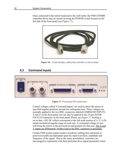
Figure 17. Front panel I/O connections.<br />
Control voltages called “Command Inputs” are used to direct the mirr<strong>or</strong> to<br />
specified angular positions around two <strong>or</strong>thogonal axes. These voltages are<br />
n<strong>or</strong>mally applied to the two BNC connect<strong>or</strong>s labeled COMMAND INPUTS<br />
X and Y on the front panel, but can also be applied to the 25-pin INTER-<br />
FACE I/O connect<strong>or</strong> on the front panel. Please see Figure 17. Scaling is<br />
set so that ±10V DC offsets c<strong>or</strong>respond to the full-scale motion of ±1.5° (±26<br />
mrad) mechanical angular range on each axis. A command voltage of zero<br />
will bring the mirr<strong>or</strong> to the powered-on null position f<strong>or</strong> that axis. The X and<br />
Y inputs are differential. Neither lead of the BNC connect<strong>or</strong> is grounded.<br />
Certain <strong>FSM</strong> system output results (overshoot, settling time and point-topoint<br />
travel path) are dependant upon the input wavef<strong>or</strong>m, amplitude and<br />
frequency of the signal. Due to the many possibilities, customers are<br />
encouraged to experiment with their particular drive signal parameters when