FSM-300 or FSM-320 Fast Steering Mirror & FSM-CD300B ...
FSM-300 or FSM-320 Fast Steering Mirror & FSM-CD300B ...
FSM-300 or FSM-320 Fast Steering Mirror & FSM-CD300B ...

Create successful ePaper yourself
Turn your PDF publications into a flip-book with our unique Google optimized e-Paper software.
System Components 23<br />
5. System Components<br />
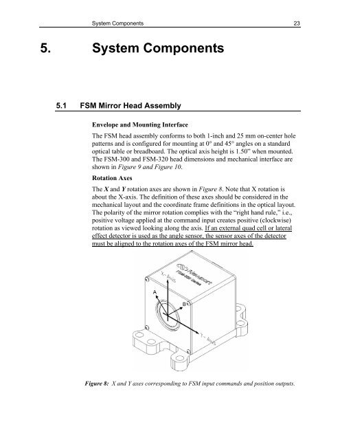
5.1 <strong>FSM</strong> Mirr<strong>or</strong> Head Assembly<br />
Envelope and Mounting Interface<br />
The <strong>FSM</strong> head assembly conf<strong>or</strong>ms to both 1-inch and 25 mm on-center hole<br />
patterns and is configured f<strong>or</strong> mounting at 0° and 45° angles on a standard<br />
optical table <strong>or</strong> breadboard. The optical axis height is 1.50” when mounted.<br />
The <strong>FSM</strong>-<strong>300</strong> and <strong>FSM</strong>-<strong>320</strong> head dimensions and mechanical interface are<br />
shown in Figure 9 and Figure 10.<br />
Rotation Axes<br />
The X and Y rotation axes are shown in Figure 8. Note that X rotation is<br />
about the X-axis. The definition of these axes should be considered in the<br />
mechanical layout and the co<strong>or</strong>dinate frame definitions in the optical layout.<br />
The polarity of the mirr<strong>or</strong> rotation complies with the “right hand rule,” i.e.,<br />
positive voltage applied at the command input creates positive (clockwise)<br />
rotation as viewed looking along the axis. If an external quad cell <strong>or</strong> lateral<br />
effect detect<strong>or</strong> is used as the angle sens<strong>or</strong>, the sens<strong>or</strong> axes of the detect<strong>or</strong><br />
must be aligned to the rotation axes of the <strong>FSM</strong> mirr<strong>or</strong> head.<br />
Figure 8: X and Y axes c<strong>or</strong>responding to <strong>FSM</strong> input commands and position outputs.