FSM-300 or FSM-320 Fast Steering Mirror & FSM-CD300B ...
FSM-300 or FSM-320 Fast Steering Mirror & FSM-CD300B ...
FSM-300 or FSM-320 Fast Steering Mirror & FSM-CD300B ...

Create successful ePaper yourself
Turn your PDF publications into a flip-book with our unique Google optimized e-Paper software.
System Components 35<br />
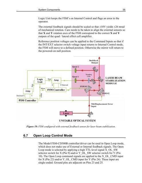
Logic Unit keeps the <strong>FSM</strong>’s on Internal Control and flags an err<strong>or</strong> to the<br />
operat<strong>or</strong>.<br />
The external feedback signals should be scaled so that ±10V yields ±26 mrad<br />
of mechanical rotation. Care needs to be taken to align the external sens<strong>or</strong>s so<br />
that X and Y rotation axes of the <strong>FSM</strong> c<strong>or</strong>respond to the c<strong>or</strong>rect X and Y<br />
outputs of the quad / lateral effect cell amplifier.<br />
Reference position voltages can be applied to the Command Inputs so that if<br />
the INT/EXT select<strong>or</strong> switch voltage input returns to Internal Control mode,<br />
the <strong>FSM</strong> will move to a defined position. Otherwise the mirr<strong>or</strong> will return to<br />
the powered-on null position.<br />
Figure 19: <strong>FSM</strong> configured with external feedback sens<strong>or</strong> f<strong>or</strong> laser beam stabilization.<br />
6.7 Open Loop Control Mode<br />
The Model <strong>FSM</strong>-CD<strong>300</strong>B controller/driver can be used in Open Loop mode,<br />
which does not make use of External <strong>or</strong> Internal feedback signals. The Open<br />
Loop mode is selected by applying a high TTL-level signal X_OL_SW<br />
select<strong>or</strong> switch f<strong>or</strong> X (Pin 9) and/<strong>or</strong> Y_OL_SW select<strong>or</strong> switch f<strong>or</strong> Y (Pin<br />
10). The Open Loop command signals are applied to the X_OL_CMD input<br />
f<strong>or</strong> X (Pin 22) and/<strong>or</strong> Y_OL_CMD input f<strong>or</strong> Y (Pin 24). These input are<br />
single-ended. Ground pins are adjacent on Pins 23 and 25.