FSM-300 or FSM-320 Fast Steering Mirror & FSM-CD300B ...
FSM-300 or FSM-320 Fast Steering Mirror & FSM-CD300B ...
FSM-300 or FSM-320 Fast Steering Mirror & FSM-CD300B ...

You also want an ePaper? Increase the reach of your titles
YUMPU automatically turns print PDFs into web optimized ePapers that Google loves.
Pin<br />
Controller<br />
Pin<br />
<strong>FSM</strong> Head<br />
System Components 29<br />
Name<br />
Type<br />
Controller<br />
1 6 +15VA DC power <strong>FSM</strong> positive 15V power<br />
2 11 -15VA DC power <strong>FSM</strong> negative 15V power<br />
Description<br />
3 2 B- Analog input B axis position sens<strong>or</strong> negative (±10V)<br />
4 8 B_RTN Analog output B axis actuat<strong>or</strong> drive return<br />
5 13 B_OUT Analog output B axis actuat<strong>or</strong> drive output<br />
6 4 A- Analog input A axis position sens<strong>or</strong> negative (±10V)<br />
7 10 A_RTN Analog output A axis actuat<strong>or</strong> drive return<br />
8 15 A_OUT Analog output A axis actuat<strong>or</strong> drive output<br />
9 1 GND Analog ground <strong>FSM</strong> ground reference and power return<br />
10 7 B+ Analog input B axis position sens<strong>or</strong> positive (±10V)<br />
11 12 B_TEMP_RTN Analog ground B axis temperature sens<strong>or</strong> return (Analog Ground)<br />
12 3 B_TEMP Analog input B axis temperature sens<strong>or</strong> signal<br />
13 9 A+ Analog input A axis position sens<strong>or</strong> positive (±10V)<br />
14 14 A_TEMP_RTN Analog ground A axis temperature sens<strong>or</strong> return (Analog Ground)<br />
15 5 A_TEMP Analog input A axis temperature sens<strong>or</strong> signal<br />
Table 1. <strong>FSM</strong> pinout descriptions of 15-pin interface cable.<br />
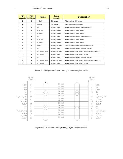
Figure 14: <strong>FSM</strong> pinout diagram of 15-pin interface cable.