Tunable Bandpass Fiber Optic Filter
Tunable Bandpass Fiber Optic Filter
Tunable Bandpass Fiber Optic Filter

Create successful ePaper yourself
Turn your PDF publications into a flip-book with our unique Google optimized e-Paper software.
Photonics and Instrumentation<br />
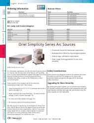
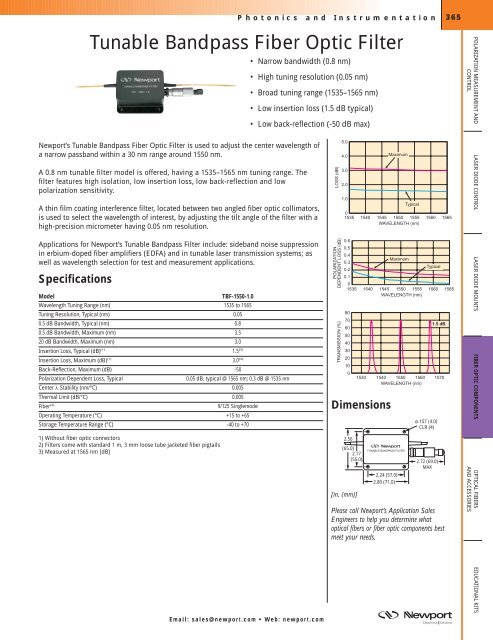
<strong>Tunable</strong> <strong>Bandpass</strong> <strong>Fiber</strong> <strong>Optic</strong> <strong>Filter</strong><br />
• Narrow bandwidth (0.8 nm)<br />
Newport’s <strong>Tunable</strong> <strong>Bandpass</strong> <strong>Fiber</strong> <strong>Optic</strong> <strong>Filter</strong> is used to adjust the center wavelength of<br />
a narrow passband within a 30 nm range around 1550 nm.<br />
A 0.8 nm tunable filter model is offered, having a 1535–1565 nm tuning range. The<br />
filter features high isolation, low insertion loss, low back-reflection and low<br />
polarization sensitivity.<br />
• High tuning resolution (0.05 nm)<br />
• Broad tuning range (1535–1565 nm)<br />
• Low insertion loss (1.5 dB typical)<br />
• Low back-reflection (-50 dB max)<br />
A thin film coating interference filter, located between two angled fiber optic collimators,<br />
is used to select the wavelength of interest, by adjusting the tilt angle of the filter with a<br />
high-precision micrometer having 0.05 nm resolution.<br />
Applications for Newport’s <strong>Tunable</strong> <strong>Bandpass</strong> <strong>Filter</strong> include: sideband noise suppression<br />
in erbium-doped fiber amplifiers (EDFA) and in tunable laser transmission systems; as<br />
well as wavelength selection for test and measurement applications.<br />
Specifications<br />
Model TBF-1550-1.0<br />
Wavelength Tuning Range (nm) 1535 to 1565<br />
Tuning Resolution, Typical (nm) 0.05<br />
0.5 dB Bandwidth, Typical (nm) 0.8<br />
0.5 dB Bandwidth, Maximum (nm) 3.5<br />
20 dB Bandwidth, Maximum (nm) 3.0<br />
Insertion Loss, Typical (dB) (1) 1.5 (3)<br />
Insertion Loss, Maximum (dB) (1)<br />
3.0 (3)<br />
Back-Reflection, Maximum (dB) -50<br />
Polarization Dependent Loss, Typical 0.05 dB, typical @ 1565 nm; 0.3 dB @ 1535 nm<br />
Center λ Stability (nm/°C) 0.005<br />
Thermal Limit (dB/°C) 0.005<br />
<strong>Fiber</strong> (2) 9/125 Singlemode<br />
Operating Temperature (°C) +15 to +65<br />
Storage Temperature Range (°C) -40 to +70<br />
1) Without fiber optic connectors<br />
2) <strong>Filter</strong>s come with standard 1 m, 3 mm loose tube jacketed fiber pigtails<br />
3) Measured at 1565 nm [dB]<br />
Email: sales@newport.com • Web: newport.com<br />
LOSS (dB)<br />
POLARIZATION<br />
DEPENDENT LOSS (dB)<br />
TRANSMISSION (%)<br />
5.0<br />
4.0<br />
3.0<br />
2.0<br />
1.0<br />
0<br />
1535<br />
0.6<br />
0.5<br />
0.4<br />
0.3<br />
0.2<br />
0.1<br />
0<br />
1535<br />
80<br />
70<br />
60<br />
50<br />
40<br />
30<br />
20<br />
10<br />
0<br />
Maximum<br />
Typical<br />
1540 1545 1550 1555 1560 1565<br />
WAVELENGTH (nm)<br />
1530<br />
Dimensions<br />
2.56<br />
(65.0)<br />
2.17<br />
(55.0)<br />
[in. (mm)]<br />
Maximum<br />
Typical<br />
365<br />
1540 1545 1550 1555 1560 1565<br />
WAVELENGTH (nm)<br />
1540 1550 1560<br />
WAVELENGTH (nm)<br />
TUNABLE BANDPASS FILTER<br />
2.24 (57.0)<br />
2.80 (71.0)<br />
CLR (4)<br />
2.72 (69.0)<br />
MAX<br />
1.5 dB<br />
1570<br />
Please call Newport’s Application Sales<br />
Engineers to help you determine what<br />
optical fibers or fiber optic components best<br />
meet your needs.<br />
POLARIZATION MEASUREMENT AND<br />
CONTROL<br />
LASER DIODE CONTROL LASER DIODE MOUNTS<br />
FIBER OPTIC COMPONENTS OPTICAL FIBERS<br />
AND ACCESSORIES<br />
EDUCATIONAL KITS
POLARIZATION MEASUREMENT AND<br />
CONTROL<br />
LASER DIODE MOUNTS LASER DIODE CONTROL<br />
FIBER OPTIC COMPONENTS<br />
OPTICAL FIBERS<br />
AND ACCESSORIES<br />
EDUCATIONAL KITS<br />
366<br />
Photonics and Instrumentation<br />
Ordering Information<br />
Model Description Option Code (1)<br />
TBF-1550-1.0 <strong>Tunable</strong> <strong>Bandpass</strong> <strong>Filter</strong>, 1550 nm, 9/125 Pigtails, No Connectors 15<br />
1) Use only when ordering with fiber optic connectors<br />
To order your <strong>Fiber</strong> <strong>Optic</strong> <strong>Filter</strong> with fiber optic connectors, use the following part number:<br />
Example: FLTR-OPT-50-15-55<br />
TBF-1550-1.0 filter with FC/SPC connector<br />
on input and FC/APC connector on output.<br />
FLTR-OPT- - - <br />
Input<br />
Connector<br />
Code<br />
<strong>Filter</strong><br />
Model<br />
Code<br />
Output<br />
Connector<br />
Code<br />
If only a single connector is required, use the NN in the connector field designating the<br />
unterminated end (i.e. FLTR-OPT-50-15-NN). Please see the Tutorial (see page 409) for<br />
more information on fiber optic connectors available through Newport .<br />
Note: <strong>Fiber</strong> optic connector termination costs are non-refundable due to the custom nature of the assembly.<br />
<strong>Fiber</strong> <strong>Optic</strong> Isolators<br />
Newport’s <strong>Fiber</strong> <strong>Optic</strong> Isolators are passive, fiber-pigtailed devices that reduce back<br />
reflections and backscattering of light (highly desirable in laser applications, for example).<br />
Three models are available to meet your particular isolation requirements.<br />
The standard ISC Model isolator features typical peak isolations of >40 dB and very low<br />
polarization mode dispersion.<br />
The enhanced ISS Model and supreme ISU Model isolators feature extremely low<br />
polarization mode dispersion and stable performance over a wide wavelength and<br />
temperature range.<br />
Specifications<br />
Parameter Model ISC Model ISS Model ISU<br />
Peak Isolation (dB) >40 >50 >60<br />
Minimum Isolation, (±20 nm over center<br />
wavelength) (dB)<br />
>32 >44 >48<br />
Insertion Loss, Typical (dB) (1) 0.4 1.0 0.6<br />
Insertion Loss, Maximum (dB) (1) ≤0.5 ≤1.3 ≤0.7<br />
Return Loss (Input/Output) (dB) ≥65/60 ≥60/55 ≥65/60<br />
Polarization Dependent Loss, Typical (dB)