FSM-300 or FSM-320 Fast Steering Mirror & FSM-CD300B ...
FSM-300 or FSM-320 Fast Steering Mirror & FSM-CD300B ...
FSM-300 or FSM-320 Fast Steering Mirror & FSM-CD300B ...

You also want an ePaper? Increase the reach of your titles
YUMPU automatically turns print PDFs into web optimized ePapers that Google loves.
28 System Components<br />
OL/CL<br />
X-axis<br />
OL Command<br />
OL/CL<br />
Y-axis OL Command<br />
X - axis<br />
Command<br />
X-axis<br />
Ext. Optical<br />
Feedback<br />
INT/EXT<br />
Y - axis<br />
Command<br />
X-axis<br />
Ext. Optical<br />
Feedback<br />
120/220 VAC<br />
60/50 Hz<br />
J2<br />
Internal/External<br />
Feedback<br />
directly into most wall outlets. The appropriate power c<strong>or</strong>d f<strong>or</strong> the destination<br />
country should be included with your controller. If the c<strong>or</strong>rect c<strong>or</strong>d is not<br />
present please contact your local Newp<strong>or</strong>t representative f<strong>or</strong> assistance.<br />
Pwr Supply<br />
GREEN<br />
(+)<br />
(+)<br />
(-)<br />
(-)<br />
+15VDC<br />
-15VDC<br />
X-axis<br />
Control<br />
Y-axis<br />
Control<br />
X-axis<br />
Command<br />
Y-axis<br />
Command<br />
A-axis<br />
Command<br />
X-axis<br />
Position<br />
B-axis<br />
Command<br />
Y-axis<br />
Position<br />
B-axis<br />
Position<br />
(+)<br />
(+)<br />
A-axis<br />
Position<br />
(-)<br />
A-axis<br />
Position<br />
(-)<br />
FAULT DETECTION<br />
DRIVER A<br />
I sense<br />
A-axis<br />
Position<br />
I sense<br />
A-axis<br />
Position<br />
DRIVER B<br />
B-axis<br />
Position<br />
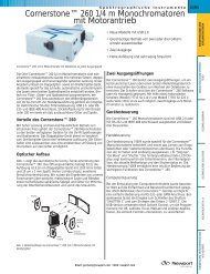
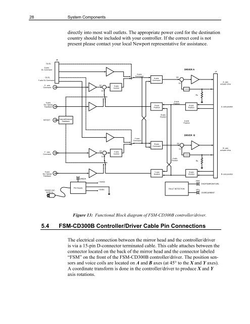
Figure 13: Functional Block diagram of <strong>FSM</strong>-CD<strong>300</strong>B controller/driver.<br />
5.4 <strong>FSM</strong>-CD<strong>300</strong>B Controller/Driver Cable Pin Connections<br />
Rs<br />
Rs<br />
RED<br />
YELL<br />
J1<br />
OVERTEMPERATURE<br />
OVERCURRENT<br />
The electrical connection between the mirr<strong>or</strong> head and the controller/driver<br />
is via a 15-pin D-connect<strong>or</strong> terminated cable. This cable attaches between the<br />
connect<strong>or</strong> located on the back of the mirr<strong>or</strong> head and the connect<strong>or</strong> labeled<br />
“<strong>FSM</strong>” on the front of the <strong>FSM</strong>-CD<strong>300</strong>B controller/driver. The position sens<strong>or</strong>s<br />
and voice coils are located on A and B axes (at 45° to the X and Y axes).<br />
A co<strong>or</strong>dinate transf<strong>or</strong>m is done in the controller/driver to produce X and Y<br />
axis rotations.<br />
A- axis<br />
actuat<strong>or</strong> drive<br />
A- axis position<br />
B- axis<br />
actuat<strong>or</strong> drive<br />
B- axis position