User s Guide - Aube Technologies inc.
User s Guide - Aube Technologies inc.
User s Guide - Aube Technologies inc.

Create successful ePaper yourself
Turn your PDF publications into a flip-book with our unique Google optimized e-Paper software.
,AI?HEFJE<br />
<strong>Aube</strong>’s TH114 Series non-programmable thermostats can be used<br />
to control ambient or floor temperature. The following models are<br />
available:<br />
A model: controls and displays the ambient temperature<br />
F model: controls and displays the floor temperature<br />
uses an external temperature sensor<br />
AF model: controls and displays the ambient temperature<br />
maintains the floor temperature within desired<br />
limits<br />
uses an external temperature sensor<br />
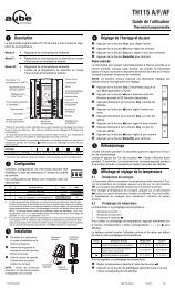
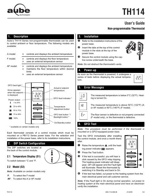
GFCI fault light *<br />
Arrow appears<br />
when the setpoint<br />
is displayed<br />
Power output<br />
1 to 24%<br />
25 to 49%<br />
50 to 74%<br />
75 to 99%<br />
100%<br />
* available on certain models only<br />
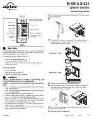
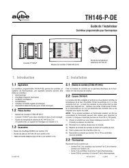
Each thermostat consists of a control module which must be<br />
mounted on a PB112 Series power base. For the selection and<br />
installation of the power base, refer to its installation instructions.<br />
,12 5MEJ?D +BECKH=JE<br />
The DIP switches are located at<br />
the back of the control module.<br />
6AFAH=JKHA ,EIF=O 5<br />
To switch between °C and °F.<br />
@A 5<br />
Note: Available on certain models only<br />
F: To select the F model<br />
AF: To select the A or AF model<br />
Actual or setpoint<br />
temperature<br />
GFCI fault indicator *<br />
Temperature<br />
adjustment button<br />
GFCI test button * /<br />
Backlight button *<br />
On/Standby button<br />
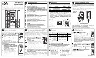
! 1IJ==JE<br />
Refer to the installation instructions of the<br />
power base.<br />
Insert the tabs at the top of the control<br />
module in the slots at the top of the<br />
power base.<br />
Secure the control module using the captive<br />
screw underneath the base.<br />
Note: Do not obstruct the thermostat's vents.<br />
" 2MAHKF<br />
60 "<br />
7IAH I /KE@A<br />
FHCH==>A 6DAHIJ=J<br />
As soon as the thermostat is powered, it undergoes a<br />
series of tests before displaying the actual temperature.<br />
# -HHH AII=CAI<br />
$ /.+1 6AIJ<br />
The measured temperature is below 0°C (32°F). Heating<br />
is turned On.<br />
The measured temperature is above 50°C (122°F) (A<br />
or AF model) or 60°C (140°F) (F model).<br />
The floor sensor is defective or not properly connected<br />
(F model only), or the thermostat is defective.<br />
Note: This procedure must be performed if the thermostat is<br />
mounted on a GFCI-equipped power base.<br />
Test the GFCI immediately after installing<br />
the control module, and once a month thereafter.<br />
Raise the temperature until the heating<br />
power indicator appears.<br />
Press the Test button.<br />
If the test is successful, you will hear a<br />
click caused by the GFCI relay tripping.<br />
The heating power indicator will disappear,<br />
GFI will appear and the Fault light<br />
will illuminate. Reset the thermostat by<br />
switching it to Standby and back to On.<br />
If the test has failed, cut power to the heating system from the<br />
main electrical panel and call customer service.<br />
Note: If the Fault light is On during normal operation, cut power to<br />
heating system at the main electrical panel and have an electrician<br />
verify the installation.<br />
TH114 400-114-000-B 21/2/05 1/2
% *=?ECDJ<br />
When either of the buttons is pressed, the display is lit for 10<br />
seconds. The setpoint appears for 5 seconds, then the actual temperature<br />
is displayed.<br />
When the backlight button is pressed, the display is lit for 5 seconds.<br />
NOTE: If the thermostat is mounted on a GFCI-equipped<br />
power base, this button is used for the GFCI test.<br />
% ,EIF=OEC =@ 5AJJEC JDA 6AFAH=JKHA<br />
The thermostat normally displays the actual temperature. To view<br />
the setpoint, press once on one of the buttons. The setpoint is<br />
displayed for 5 seconds. During the setpoint display, press one of<br />
the buttons to change it. To scroll the setpoint faster, press<br />
and hold the button.<br />
%! 5AJJEC JDA .H 6AFAH=JKHA EEJI ). @A O<br />
The thermostat generally turns heating On or Off to control<br />
the ambient temperature. However, if the floor temperature<br />
drops below the set minimum floor temperature<br />
limit or rises above the maximum limit, the thermostat<br />
will turn heating On or Off respectively, regardless of the<br />
ambient temperature, to maintain the floor temperature<br />
within the desired limits.<br />
The minimum and maximum floor temperature limits are<br />
factory-set at 10°C (50°F) and 28°C (82°F) respectively. To modify<br />
the limits, proceed as follows:<br />
Switch the thermostat to Standby.<br />
While pressing any button, switch the thermostat back to On to<br />
access the floor temperature limit settings.<br />
Press the Test button briefly to switch between minimum and<br />
maximum floor temperature settings.<br />
Press the buttons to set the desired limit.<br />
Press the Test button for 3 seconds to save your modifications.<br />
After the data are saved, the thermostat displays the actual<br />
ambient temperature or “– –”.<br />
Note: Your modifications are also saved if no button is pressed for<br />
60 seconds.<br />
Switch the thermostat to Standby and back to On to reset the<br />
GFCI and return to the normal display.<br />
:<br />
% FAH=JE & 6A?DE?= 5FA?EBE?=JEI<br />
Power supply: Refer to the power base installation instructions.<br />
Ambient setpoint range (A/AF models): 5°C to 30°C (40°F - 86°F)<br />
Floor limit range (AF model): 5°C to 40°C (40°F - 104°F)<br />
Floor setpoint range (F model): 5°C to 40°C (40°F - 104°F)<br />
Setpoint resolution: ± 0.5°C (1.0°F)<br />
Display resolution: ± 0.5°C (1.0°F)<br />
Duty cycle: Refer to the power base installation instructions.<br />
Storage: -20°C to 50°C (-4°F - 120°F)<br />
' 9=HH=JO<br />
AUBE TECHNOLOGIES INC. ONE (1) YEAR LIMITED WARRANTY<br />
This product is guaranteed against workmanship defects for a one<br />
year period following the initial date of purchase. During this period,<br />
AUBE <strong>Technologies</strong> Inc. will repair or replace, at our option and<br />
without charge, any defective product which has been used under<br />
normal conditions.<br />
The warranty does not cover delivery costs and does not apply to<br />
products poorly installed or randomly damaged following installation.<br />
This warranty cancels and replaces any other manufacturer's<br />
express or implied warranty as well as any other company commitment.<br />
AUBE <strong>Technologies</strong> Inc. cannot be held liable for related or random<br />
damages following the installation of this product. The defective<br />
product as well as the purchase invoice must be returned to the<br />
place of purchase or mailed, prepaid and insured, to the following<br />
address.<br />
5AHLE?A<br />
705 Montrichard<br />
Saint-Jean-sur-Richelieu, Quebec<br />
J2X 5K8<br />
Canada<br />
T: (450) 358-4600<br />
1-800-831-AUBE (2823)<br />
F: (450) 358-4650<br />
service@aubetech.com<br />
For more information on our products, visit us at:<br />
www.aubetech.com<br />
TH114 400-114-000-B 21/2/05 2/2
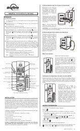
Applications<br />
The PB112-024T-15S power base can be used on any TH11x series<br />
thermostat (with the exception of the TH110 model). This low-voltage<br />
power base operates on 15-second cycles and can be connected to<br />
a line-voltage load using a solid-state relay. The PB112-024T-15S is<br />
compatible with most solid-state relays; however, the following <strong>Aube</strong><br />
relays are optimized for use with this power base:<br />
• RT850 solid-state relay (SSR)<br />
• RT850T solid-state relay (SSR) with built-in 24-V transformer<br />
One (1) power base<br />
Two (2) plastic anchors<br />
Two (2) mounting screws<br />
WARNING<br />
This power base MUST be used ONLY with solid-state relays. The<br />
use of electromechanical relays will result in reduced life expectancy<br />
and in the possibility of overheating of these devices.<br />
<br />
<br />
For a new installation, choose a location about 1.5 m (5 ft.)<br />
above the floor.<br />
The thermostat must be installed on an inside wall facing the<br />
heating system (except for floor heating systems).<br />
Avoid locations where there are air drafts (top of staircase, air<br />
outlet), dead air spots (behind a door), direct sunlight or<br />
concealed chimney or stove pipes (except for floor heating<br />
systems).<br />
<br />
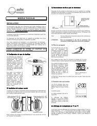
Supplied Parts<br />
Installation <strong>Guide</strong>lines<br />
Installation Procedure<br />
The installation must be carried out by an electrician and comply<br />
with local electrical codes.<br />
Turn off power to the heating system at the main electrical panel<br />
to avoid electrical shock.<br />
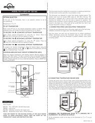
Wire the base according to your application. See typical wiring<br />
diagrams in sections 4.1 and 4.2.<br />
For a floor heating system installation, connect<br />
the floor sensor between the S and R terminals.<br />
Secure the base to the wall using the provided screws and wall<br />
anchors.<br />
Configure the switches located on the control module (if any).<br />
Refer to the user guide.<br />
1.<br />
2.<br />
3.<br />
4.<br />
Install the control module onto the base.<br />
Apply power to the heating system.<br />
Verify the installation by checking that the heating system can be<br />
turned on or off using the thermostat.<br />
4.1 Single SSR with Built-in Transformer<br />
4.2 Multiple SSRs with External Transformer<br />
Maximum load: 0.5 A / 24 VAC<br />
Heating cycle length: 15 seconds<br />
Operating temperature: 32°F to 122°F (0°C to 50°C)<br />
Storage: -4°F to 122°F (-20°C to 50°C)<br />
Size (H•W•D): 124 x 70 x 23 mm (4.89 x 2.76 x 0.91 in)<br />
Wire gauge: 14 to 22 AWG<br />
PB112-024T-15S 400-112-024-A 18/1/06 1/1<br />
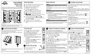
<br />
Electrical<br />
Panel<br />
Electrical<br />
Panel<br />
Heater<br />
Heater<br />
Blue Red<br />
Black<br />
Technical Specifications<br />
PB112-024T-15S<br />
Black<br />
Red<br />
Black<br />
Red<br />
Installation Instructions<br />
24 V Low-Voltage Power Base<br />
Heater<br />
External 24 V<br />
Transformer<br />
5.