400-280-007-B (TH146-N-U) ENG.fm - Master
400-280-007-B (TH146-N-U) ENG.fm - Master
400-280-007-B (TH146-N-U) ENG.fm - Master

Create successful ePaper yourself
Turn your PDF publications into a flip-book with our unique Google optimized e-Paper software.
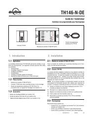
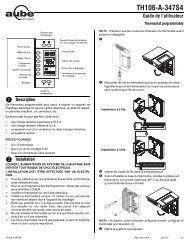
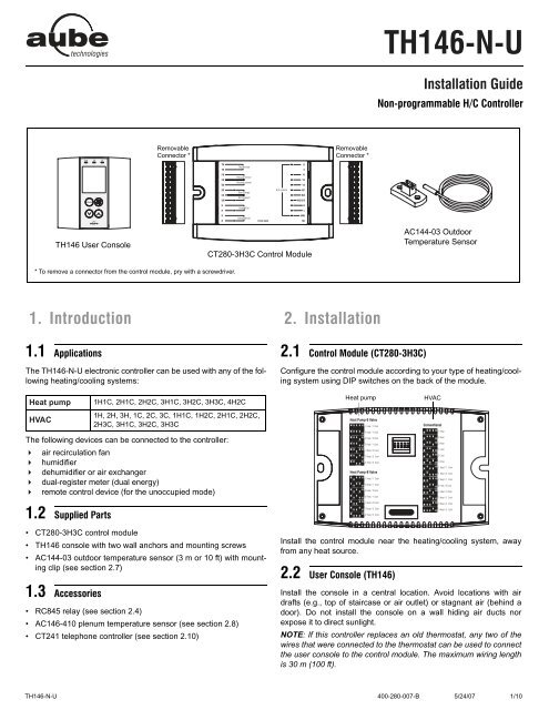
<strong>TH146</strong> User Console<br />
Removable<br />
Connector *<br />
* To remove a connector from the control module, pry with a screwdriver.<br />
1. Introduction<br />
1.1 Applications<br />
The <strong>TH146</strong>-N-U electronic controller can be used with any of the following<br />
heating/cooling systems:<br />
Heat pump 1H1C, 2H1C, 2H2C, 3H1C, 3H2C, 3H3C, 4H2C<br />
HVAC<br />
The following devices can be connected to the controller:<br />
air recirculation fan<br />
humidifier<br />
dehumidifier or air exchanger<br />
dual-register meter (dual energy)<br />
remote control device (for the unoccupied mode)<br />
1.2 Supplied Parts<br />
• CT<strong>280</strong>-3H3C control module<br />
• <strong>TH146</strong> console with two wall anchors and mounting screws<br />
• AC144-03 outdoor temperature sensor (3 m or 10 ft) with mounting<br />
clip (see section 2.7)<br />
1.3 Accessories<br />
• RC845 relay (see section 2.4)<br />
• AC146-410 plenum temperature sensor (see section 2.8)<br />
• CT241 telephone controller (see section 2.10)<br />
CT<strong>280</strong>-3H3C Control Module<br />
1H, 2H, 3H, 1C, 2C, 3C, 1H1C, 1H2C, 2H1C, 2H2C,<br />
2H3C, 3H1C, 3H2C, 3H3C<br />
Removable<br />
Connector *<br />
2. Installation<br />
2.1 Control Module (CT<strong>280</strong>-3H3C)<br />
<strong>TH146</strong>-N-U<br />
Installation Guide<br />
Non-programmable H/C Controller<br />
AC144-03 Outdoor<br />
Temperature Sensor<br />
Configure the control module according to your type of heating/cooling<br />
system using DIP switches on the back of the module.<br />
Heat pump HVAC<br />
Install the control module near the heating/cooling system, away<br />
from any heat source.<br />
2.2 User Console (<strong>TH146</strong>)<br />
Install the console in a central location. Avoid locations with air<br />
drafts (e.g., top of staircase or air outlet) or stagnant air (behind a<br />
door). Do not install the console on a wall hiding air ducts nor<br />
expose it to direct sunlight.<br />
NOTE: If this controller replaces an old thermostat, any two of the<br />
wires that were connected to the thermostat can be used to connect<br />
the user console to the control module. The maximum wiring length<br />
is 30 m (100 ft).<br />
<strong>TH146</strong>-N-U <strong>400</strong>-<strong>280</strong>-<strong>007</strong>-B 5/24/07 1/10
Choose a location about 1.5 m (5 ft) above the floor on an<br />
inside wall.<br />
Loosen the captive screw under the console.<br />
Detach the console from its base by pulling the bottom section.<br />
Secure the base using the wall anchors and screws.<br />
Connect the console to controller terminals TH and TH (no<br />
polarity).<br />
2.3 Heating/Cooling System<br />
The terminals used to connect the heating/cooling system depend<br />
on the type of system. See the appropriate wiring table on page 4.<br />
2.4 RC845 Relay<br />
If you have an add-on installation, you might need an RC845 relay<br />
to connect the furnace (auxiliary heat) and its fan to the controller.<br />
Install the relay near the control module and connect the wires as<br />
follows:<br />
• relay terminals W, G and C to controller terminals W1, G and C.<br />
• relay terminals T and T to the appropriate furnace terminals: T<br />
and T (oil); TH and TH (gas); R and W (electric).<br />
NOTE: Refer to the relay’s installation instructions for more details.<br />
If you have a 3H1C or 4H2C heat pump, a second RC845 relay<br />
might be required to connect the second auxiliary heat.<br />
2.5 Humidifier<br />
Connect the humidifier in series with the power supply between<br />
controller terminals H and H (dry contact).<br />
2.6 Dehumidifier / Air Exchanger<br />
Connect the dehumidifier or air exchanger in series with the power<br />
supply between controller terminals D and D (dry contact).<br />
2.7 Outdoor Sensor (AC144-03)<br />
The outdoor sensor is required for the following:<br />
• outdoor temperature display<br />
• balance points (heat pumps only, see section 4.2)<br />
• defrost point (heat pumps only, see section 4.3)<br />
• automatic humidity control (see section 5.5)<br />
When installing the sensor, observe the following guidelines:<br />
• Avoid locations where the sensor can be covered with snow<br />
or exposed to direct sunlight.<br />
• Avoid air outlets and concealed chimneys or stove pipes.<br />
Install the sensor using its mounting clip and connect it to controller<br />
terminals OS and CS (no polarity).<br />
NOTE: The maximum wiring length is 30 m (100 ft).<br />
2.8 Plenum Sensor (AC146-410)<br />
The plenum sensor is required for the following:<br />
• low temperature limit inside the plenum (HVAC only)<br />
• high temperature limit inside the plenum (HVAC only)<br />
• fan limit if gas heating is used (HVAC only)<br />
• high pressure protection during defrost cycle (This protection<br />
is generally needed for add-on installations only. It is not<br />
needed if the heat pump is not connected to the controller<br />
terminal WW.)<br />
Install the sensor on the side of the plenum and<br />
position it such that its aperture faces the air flow.<br />
Connect the sensor to controller terminals PS<br />
and CS (no polarity). For more information, refer<br />
to the instructions provided with the sensor.<br />
NOTE: The maximum wiring length is 30 m (100<br />
ft).<br />
2.9 Dual-energy Input<br />
NOTE: The dual-energy input can be used only with a heat pump<br />
equipped with auxiliary heat.<br />
The dual-energy input can be connected to the dual-register meter<br />
equipped with a normally open (NO) dry contact. Connect the controller<br />
terminals DE and CC to the meter terminals (yellow and red<br />
wires).<br />
The contact closes when the outdoor temperature drops below the<br />
temperature setting on the meter. When the contact is closed, the<br />
heat pump is disabled and only the auxiliary heat can be used.<br />
2.10 Unoccupied Mode Input<br />
To use the unoccupied mode, the controller requires a remote control<br />
device such as Aube’s CT241 telephone controller equipped<br />
with a normally open (NO) dry contact placed between terminals UN<br />
and CC of the controller. The unoccupied mode is activated when<br />
the contact closes. (See section 5.6.)<br />
3. Configuration<br />
3.1 Configuration Switches<br />
To access the configuration switches, loosen the captive screw<br />
under the console and separate the console from its base by pulling<br />
it from the bottom part.<br />
3.1.1 Backlight (SW1-1)<br />
BL ON: The screen is always backlit.<br />
AUTO: The screen is backlit only when a button is pressed. The<br />
backlight remains on for 12 seconds.<br />
3.1.2 Access Mode (SW1-2)<br />
INST: Installer mode. Gives access to all configuration parameters.<br />
NOTE: In installer mode, the short-cycle protection is disabled<br />
and the interstage delay is reduced to 1 minute.<br />
USER: User mode. Gives access to configuration parameter 17<br />
(humidity setpoint or humidity offset) only.<br />
3.1.3 Keypad Lock (SW1-3)<br />
I: The keypad is locked. Settings cannot be changed.<br />
O: The keypad is unlocked.<br />
3.2 Software Configuration<br />
Place the console in Installer mode (INST) using the SW1-2 switch<br />
on the back of the console.<br />
Press the Mode button for 3 seconds to access the configuration<br />
menu (see page 8). The first menu item (parameter) is displayed.<br />
To view another menu item, briefly press the Mode button.<br />
To modify a parameter, press either button.<br />
To exit the configuration menu, press .<br />
Return the console to User mode (USER).<br />
<strong>TH146</strong>-N-U <strong>400</strong>-<strong>280</strong>-<strong>007</strong>-B 5/24/07 2/10
4. Principles of Operation<br />
4.1 Automatic Heating/Cooling Changeover<br />
With automatic heating/cooling mode changeover, there’s no need<br />
to adjust the controller at every change of season or weather condition.<br />
The controller switches automatically between heating mode<br />
and cooling mode to maintain the desired temperature. The mode<br />
changeover is triggered as follows:<br />
• The controller switches to cooling mode when the indoor temperature<br />
is higher than the setpoint by more than 1.5°C (2.5°F)<br />
for 15 minutes.<br />
• The controller switches to heating mode when the indoor temperature<br />
is lower than the setpoint by more than 1.5°C (2.5°F)<br />
for 15 minutes.<br />
4.2 Balance Points (heat pumps only)<br />
Balance points are used to disable the heat pump or the auxiliary<br />
heating when the outdoor temperature is below or above a set temperature.<br />
• When the outdoor temperature is below the balance point low<br />
(bP L), the heat pump is disabled and only auxiliary heating can<br />
be used (see page 8, item 2).<br />
• When the outdoor temperature is above the balance point high<br />
(bP H), the auxiliary heat is disabled and only the heat pump<br />
can be used (see page 8, item 3).<br />
NOTE: Balance Points cannot be used if the AC144-03 outdoor<br />
temperature sensor is not connected to the controller.<br />
4.3 Heating During Defrost (heat pumps only)<br />
The auxiliary heat is activated during defrost except under the following<br />
conditions:<br />
• When the outdoor temperature is above the defrost point (see<br />
page 8, item 4). Note: This condition will not apply if the<br />
AC144-03 outdoor sensor is not connected to the controller.<br />
• When the plenum temperature is above 40°C (104°F). The<br />
auxiliary heat is re-activated when the plenum temperature<br />
drops below 32°C (90°F). Note: This condition will not apply if<br />
the AC146-410 plenum sensor is not connected to the controller.<br />
NOTE: The auxiliary heat’s short-cycle protection is disabled during<br />
defrost.<br />
4.4 Types of Heat Pump Installations<br />
The controller can be configured for either of the following types of<br />
heat pump installations (see page 8, item 5).<br />
• Add-on Installation: This type of installation is performed<br />
when adding a heat pump to an existing furnace. When the<br />
heat pump is installed, the furnace becomes the auxiliary heat<br />
source. In this type of installation, the indoor coils are usually<br />
installed downstream of the auxiliary heat source. When the<br />
controller is configured for an add-on installation, the heat<br />
pump is disabled during auxiliary heating to prevent overpressure.<br />
• New Installation: In this type of installation, as there is not<br />
already a furnace, the auxiliary heat source is installed at the<br />
same time as the heat pump. In this type of installation, the<br />
indoor coils are located upstream of the auxiliary heat. When<br />
the controller is configured for a new installation, the heat pump<br />
and the auxiliary heat can operate simultaneously.<br />
4.5 Interstage Delay<br />
Interstage Delay is the time allocated for the temperature to return<br />
to an acceptable value when it deviates too far from the setpoint. If<br />
this time has elapsed, the next heating or cooling stage is activated.<br />
The heating or cooling stage will be deactivated when the temperature<br />
returns to an acceptable value. The Interstage Delay is fixed at<br />
4 minutes if the controller is configured for an HVAC system and is<br />
user-adjustable if it is configured for a heat pump (see page 8,<br />
item 6).<br />
4.6 Low and High Temperature Limits<br />
Low Temperature Limit (LLMT) and High Temperature Limit (HLMT)<br />
are used to keep the plenum from becoming too cold or too hot.<br />
During cooling, if the plenum temperature is lower than LLMT, a<br />
cooling stage is deactivated starting with the one that was last activated.<br />
If, after a while, the temperature is still too low, another cooling<br />
stage is deactivated and so on. Likewise, during heating, if the<br />
plenum temperature is higher than HLMT, a heating stage is deactivated<br />
starting with the one that was last activated. If, after a while,<br />
the temperature is still too high, another heating stage is deactivated<br />
and so on. (see page 8, items 7 and 8.)<br />
WARNING: LLMT and HLMT can be used in parallel with an<br />
UL353-approved device but they do not replace such device.<br />
NOTE: LLMT and HLMT cannot be used if the plenum temperature<br />
sensor is not connected to the controller.<br />
4.7 Smart Fan<br />
When Smart Fan is enabled (see page 8, item 12), the fan operates<br />
as follows:<br />
• During the unoccupied mode (i.e., when you are away from<br />
home), the fan operates only when heating or cooling is activated.<br />
• The fan operates continuously the rest of the time.<br />
NOTE: For Smart Fan to work, set the fan to On (see section 5.2).<br />
4.8 Automatic Humidification / Dehumidification Changeover<br />
If a humidifier and a dehumidifier are both connected to the controller,<br />
the controller will automatically switch between the two devices<br />
to maintain the desired humidity level. The changeover occurs when<br />
the humidity deviates from the setpoint by more than 3% for 30 minutes.<br />
<strong>TH146</strong>-N-U <strong>400</strong>-<strong>280</strong>-<strong>007</strong>-B 5/24/07 3/10
Wiring Tables<br />
Heat Pump<br />
Terminal Device 1H1C 2H1C 3H1C 2H2C 3H2C 4H2C 3H3C<br />
TH<br />
TH<br />
Console Connect the console between the TH terminals (no polarity)<br />
PS Plenum sensor Connect the plenum sensor between the PS and CS terminals (no polarity)<br />
CS Common S Common terminal for the plenum sensor and the outdoor sensor<br />
OS Outdoor sensor Connect the outdoor sensor between the CS and OS terminals (no polarity)<br />
DE Dual Energy Connect the dual-register meter between the DE and CC terminals (no polarity)<br />
CC Common C Common terminal for the dual-energy meter and the unoccupied mode input<br />
UN Unoccupied mode input Connect a dry contact between the UN and CC terminals (no polarity)<br />
H<br />
H<br />
Humidifier (24 Vac / 1 A) Connect the humidifier between the H terminals (dry contact)<br />
D<br />
D<br />
Dehumidifier (24 Vac / 1 A) Connect the dehumidifier between the D terminals (dry contact)<br />
R<br />
C<br />
Power (24 Vac)<br />
√<br />
√<br />
√<br />
√<br />
√<br />
√<br />
√<br />
√<br />
√<br />
√<br />
√<br />
√<br />
√<br />
√<br />
Y1 Compressor 1 (24 Vac / 1 A) √ √ √ √ √ √ √<br />
Y2 Compressor 2 (24 Vac / 1 A) √ √ √ √<br />
Y3 Compressor 3 (24 Vac / 1 A) √<br />
W1 Auxiliary heat 1 (24 Vac / 1 A) √ √ √ √<br />
W2 Auxiliary heat 2 (24 Vac / 1 A) √ √<br />
W3/O/B Reversing valve (24 Vac / 1 A) √ √ √ √ √ √ √<br />
G Fan (24 Vac / 1A) √ √ √ √ √ √ √<br />
L Fault (24 Vac / 5 mA) √ √ √ √ √ √ √<br />
WW Defrost (24 Vac / 5 mA) √ √ √ √ √ √ √<br />
NC Not used<br />
HVAC<br />
Terminal Device 1H 2H 3H 1C 2C 3C 1H1C 1H2C 2H1C 2H2C 2H3C 3H1C 3H2C 3H3C<br />
TH<br />
TH<br />
Console Connect the console sensor between the TH terminals (no polarity)<br />
PS Plenum sensor Connect the plenum sensor between the PS and CS terminals (no polarity)<br />
CS Common S Common terminal for both plenum sensor and outdoor sensor<br />
OS Outdoor sensor Connect the outdoor sensor between the OS and CS terminals (no polarity)<br />
DE Not used<br />
CC Common C Common terminal for the unoccupied mode input<br />
UN Unoccupied mode input Connect a dry contact between UN and R terminals (no polarity)<br />
H<br />
H<br />
Humidifier (24 Vac / 1 A) Connect the humidifier between the H terminals (dry contact)<br />
D<br />
D<br />
Dehumidifier (24 Vac / 1 A) Connect the dehumidifier between the D terminals (dry contact)<br />
R<br />
C<br />
Power (24 Vac)<br />
√<br />
√<br />
√<br />
√<br />
√<br />
√<br />
√<br />
√<br />
√<br />
√<br />
√<br />
√<br />
√<br />
√<br />
√<br />
√<br />
√<br />
√<br />
√<br />
√<br />
√<br />
√<br />
√<br />
√<br />
√<br />
√<br />
√<br />
√<br />
Y1 Cooling unit 1 (24 Vac / 1 A) √ √ √ √ √ √ √ √ √ √ √<br />
Y2 Cooling unit 2 (24 Vac / 1 A) √ √ √ √ √ √ √<br />
Y3 Cooling unit 3 (24 Vac / 1 A) √ √ √<br />
W1 Heating unit 1 (24 Vac / 1 A) √ √ √ √ √ √ √ √ √ √ √<br />
W2 Heating unit 2 (24 Vac / 1 A) √ √ √ √ √ √ √ √<br />
W3/O/B Heating unit 3 (24 Vac / 1 A) √ √ √ √<br />
G Fan (24 Vac / 1 A) √ √ √ √ √ √ √ √ √ √ √ √ √ √<br />
L Not used<br />
WW Not used<br />
NC Not used<br />
<strong>TH146</strong>-N-U <strong>400</strong>-<strong>280</strong>-<strong>007</strong>-B 5/24/07 4/10
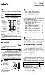
Wiring Diagram: 2H1C Heat Pump — New Installation<br />
AC146-410<br />
AC144-03<br />
Dual Energy<br />
CT241<br />
Humidifier<br />
Dehumidifier<br />
<strong>TH146</strong>-N-U <strong>400</strong>-<strong>280</strong>-<strong>007</strong>-B 5/24/07 5/10<br />
Compressor<br />
Auxiliary Heat<br />
Reversing Valve<br />
Fan<br />
Fault<br />
Defrost
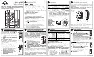
Wiring Diagram: 3H2C Heat Pump — Add-on Installation<br />
AC146-410<br />
AC144-03<br />
Dual Energy<br />
CT241<br />
Humidifier<br />
Dehumidifier<br />
Compressor 1<br />
Compressor 2<br />
Reversing Valve<br />
<strong>TH146</strong>-N-U <strong>400</strong>-<strong>280</strong>-<strong>007</strong>-B 5/24/07 6/10<br />
Furnace<br />
Fault<br />
Defrost<br />
Fan Limit
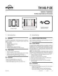
Wiring Diagram: 3H2C HVAC<br />
AC146-410<br />
AC144-03<br />
CT241<br />
Humidifier<br />
Dehumidifier<br />
Cooling Unit 1<br />
Cooling Unit 2<br />
Heating Unit 1<br />
Heating Unit 2<br />
Heating Unit 3<br />
<strong>TH146</strong>-N-U <strong>400</strong>-<strong>280</strong>-<strong>007</strong>-B 5/24/07 7/10<br />
Fan
Configuration Menu<br />
Item HP HVAC Parameters Display Options Default Description<br />
1 √ √ Temperature format °C / °F °C Select the temperature display format.<br />
2 √ Balance point low<br />
3 √ Balance point high<br />
4 √ Defrost point<br />
-30 to 10°C<br />
(-22 to 50°F)<br />
-5 to 30°C<br />
(23 to 86°F)<br />
-10 to 15°C<br />
(14 to 59°F)<br />
<strong>TH146</strong>-N-U <strong>400</strong>-<strong>280</strong>-<strong>007</strong>-B 5/24/07 8/10<br />
-10°C<br />
(14°F)<br />
5°C<br />
(41°F)<br />
10°C<br />
(50°F)<br />
5 √ Installation type Ad / nr Ad<br />
6 √<br />
Auxiliary<br />
interstage delay<br />
7 √ Low temperature limit<br />
8 √ High temperature limit<br />
Set the bP L limit (see section 4.2).<br />
NOTE: Lower bP L below its minimum (- -) if you do not wish to use this<br />
function.<br />
Set the bP H limit (see section 4.2).<br />
NOTE: Raise bP H above its maximum (- -) if you do not wish to use this<br />
function.<br />
Set the defrost point temperature (see section 4.3).<br />
NOTE: Raise the defrost point above its maximum (- -) if you do not wish to<br />
use this function.<br />
Set according to the type of heat pump installation (see section 4.4).<br />
• Ad (add-on): Use this setting when the indoor coils are located downstream<br />
of the auxiliary heat source. This is generally the case for add-on<br />
installations.<br />
• nr (normal): Select this setting when the indoor coils are located<br />
upstream of the auxiliary heat source. This is generally the case for new<br />
installations.<br />
5 to 90 min. 30 min. Set the interstage delay for the auxiliary stage (see section 4.5).<br />
-10 to 20°C<br />
(14 to 68°F)<br />
30 to 90°C<br />
(86 to 194°F)<br />
5°C<br />
(41°F)<br />
70°C<br />
(158°F)<br />
9 √ √ Cycles per hour 2 to 6 4<br />
10 √ Heat type GA / EL EL<br />
11 √ Fan limit<br />
38 to 90°C<br />
(100 to 194°F)<br />
80°C<br />
(176°F)<br />
12 √ √ Smart Fan On / OF OF<br />
13 √ √ Temperature setback<br />
14 √ √<br />
15 √ √<br />
16 √ √<br />
Outdoor temperature<br />
display<br />
Humidifier<br />
operating mode<br />
Automatic humidity<br />
adjustment<br />
0 to 9°C<br />
(0 to 16°F)<br />
0°C<br />
(0°F)<br />
On / OF On<br />
Co / HE / Fn Fn<br />
On / OF OF<br />
Humidity setpoint 5 to 60% 5 %<br />
Set the low temperature limit of the plenum (see section 4.6).<br />
NOTE: This function is not used if you lower LLMT below its minimum (- -)<br />
or if the plenum temperature sensor is not connected to the controller.<br />
Set the high temperature limit of the plenum (see section 4.6).<br />
NOTE: This function is not used if you raise HLMT above its maximum (- -)<br />
or if the plenum temperature sensor is not connected to the controller.<br />
Select the number of heating/cooling cycles per hour. For optimal heating<br />
control, use the setting that matches your system as follows: 3=20 min (hot<br />
water, 90%+ high-efficiency furnace), 4=15 min (gas or oil), 5=12 min (gas<br />
or oil), 6=10 min (electric).<br />
This setting determines the fan operation in automatic mode when the system<br />
is in heating mode (see section 5.2).<br />
• EL (electric heating): The fan starts and stops at the same time as heating.<br />
• GA (gas or oil heating): The fan starts when the temperature inside the<br />
plenum rises above the Fan Limit (see item 11) and stops when the temperature<br />
drops 12°C below the Fan Limit. Note: The fan will not start if<br />
the plenum temperature sensor is not connected to the controller.<br />
This parameter is available only when gas heating is selected (see item 10).<br />
WARNING: FLMT can be used in parallel with an UL353-approved<br />
device but they do not replace such device.<br />
NOTE: The fan will not start if you raise FLMT above its maximum (--).<br />
• On: Smart Fan is On (see section 4.7).<br />
• OF: Smart Fan is Off.<br />
Set the amount of temperature setback when the controller is placed in<br />
Unoccupied mode (see section 5.6).<br />
Select between displaying the outdoor temperature or the indoor humidity<br />
level.<br />
• On: Displays the outdoor temperature.<br />
• OF: Displays the indoor humidity level.<br />
NOTE: To display the outdoor temperature, the outdoor sensor must be<br />
connected.<br />
• Co (conventional): The humidifier will operate if the humidity is too low. If<br />
the fan is not already On, it will turn On at the same time as the humidifier.<br />
• HE (heat): The humidifier can operate only when heating is activated.<br />
• Fn (fan): The humidifier can operate as long as the fan is running,<br />
whether heating is activated or not.<br />
NOTE: The humidifier is disabled when cooling is activated.<br />
Allows you to set the humidity control to automatic mode.<br />
• On (automatic): The humidity level is automatically regulated by the controller<br />
according to the outdoor temperature to avoid condensation or ice<br />
formation on windows while providing enough humidity for your comfort<br />
(see item 17).<br />
• OF (manual): The user manually sets the humidity level (see item 17).<br />
Set the desired humidity level. This parameter is available only when the<br />
humidity control is placed in manual mode (see item 16).<br />
17 √ √<br />
Humidity offset -9 to 9% 0<br />
This parameter is available only when the humidity control is placed in automatic<br />
mode (see item 16). It allows the user to apply an offset to the automatic<br />
humidity control. For example, the user can enter a negative offset if<br />
there is ice formation or condensation on the windows.<br />
NOTE: Only the humidity setpoint or humidity offset (item 17) is available when the controller is placed in user mode (SW1-2 switch).
System fault<br />
indicator<br />
System operating<br />
mode selection<br />
5. Operation<br />
Temperature adjustment<br />
5.1 System Operating Mode<br />
Press the Mode button to place the system in one of the following<br />
modes:<br />
HEAT The system is in heating mode.<br />
COOL The system is in cooling mode.<br />
AUTO<br />
Emergency heat<br />
indicator Dual energy<br />
Fan operating<br />
mode selection<br />
The system is in automatic changeover mode. (The system<br />
switches between heating mode and cooling mode to<br />
maintain the desired temperature.)<br />
OFF The system is off.<br />
EHEAT<br />
The system is in emergency heat mode. Only auxiliary<br />
heating is used when there is a call for heat. (This mode<br />
applies only when the controller is connected to a heat<br />
pump equipped with auxiliary heating).<br />
5.2 Fan Operating Mode<br />
Press the button to select the fan operating mode.<br />
• In automatic mode, the fan runs only when heating or cooling is<br />
activated. NOTE: For gas-operated HVAC systems, there might<br />
be a delay before the fan starts or stops when heating is activated<br />
or deactivated.<br />
• In continuous mode, the fan runs continuously and the symbol<br />
is displayed. NOTE: If Smart Fan is enabled, when the thermostat<br />
is in unoccupied mode, the fan runs only when heating<br />
or cooling is activated.<br />
Auxiliary heat is On<br />
Heating is On<br />
Cooling is On<br />
Fan is in<br />
continuous mode<br />
Unoccupied<br />
mode is On<br />
<strong>TH146</strong>-N-U<br />
User’s Guide<br />
Non-programmable H/C Controller<br />
Appears when the<br />
temperature setpoint<br />
is displayed<br />
Humidifier<br />
is On<br />
Indoor temperature<br />
Outdoor temperature<br />
or indoor humidity<br />
System operating mode<br />
5.3 Indoor Humidity / Outdoor Temperature Display<br />
The controller can display either the indoor humidity level or the outdoor<br />
temperature (see page 8, item 13).<br />
Outdoor<br />
temperature<br />
5.4 Temperature Adjustment<br />
The actual (measured) indoor temperature is normally displayed. To<br />
view the setpoint temperature, press one of the buttons once.<br />
The setpoint is displayed for 5 seconds and is indicated by the<br />
symbol.<br />
To modify the temperature setpoint, press one of the buttons<br />
until the desired temperature is displayed.<br />
NOTE: If the controller is in automatic heat/cool changeover (see<br />
section 5.1), the setpoint is automatically reduced or raised by 1°C<br />
(1.8°F) when the controller switches to heating mode or to cooling<br />
mode respectively. For example, if the setpoint is 24°C (75°F) in<br />
heating mode, it will become 25°C (77°F) in cooling mode and will<br />
return to 24°C (75°F) when the controller switches back to heating<br />
mode.<br />
5.5 Humidity Adjustment<br />
Indoor<br />
humidity<br />
The humidity adjustment can be placed in manual mode or in automatic<br />
mode (see page 8, item 16).<br />
Manual Adjustment<br />
In manual adjustment, the user sets the humidity level (5 to 60%).<br />
Automatic Adjustment<br />
In automatic adjustment, the controller sets the humidity level based<br />
on the outdoor temperature to prevent ice formation or condensa-<br />
<strong>TH146</strong>-N-U <strong>400</strong>-<strong>280</strong>-<strong>007</strong>-B 5/24/07 9/10
tion on windows. However, the user can apply an offset (-9 to 9%).<br />
For example, the user can enter a negative offset if there is too<br />
much condensation on the windows.<br />
Procedure<br />
The procedure to set the humidity level (in manual mode) or the offset<br />
(in automatic mode) is as follows:<br />
1) Press the Mode button for 3 seconds.<br />
One of the following displays appears:<br />
Humidity<br />
level set<br />
by user<br />
2) Set the humidity level or offset using the buttons.<br />
• humidity level: 5 to 60%<br />
• offset: -9 to 9%<br />
3) Press the button to exit.<br />
The symbol is displayed when the humidifier is On.<br />
5.6 Unoccupied Mode<br />
You can place the controller in the unoccupied mode using a remote<br />
control device such as Aube’s CT241 telephone controller. In this<br />
mode, the temperature is lowered in heating mode or raised in cooling<br />
mode (see page 8, item 13). The icon appears during the<br />
unoccupied mode.<br />
NOTE: Automatic heating/cooling changeover is disabled during the<br />
unoccupied mode.<br />
5.7 Temporary Bypass<br />
If you change the temperature setpoint (using the buttons) in<br />
unoccupied mode, the controller temporarily bypasses the current<br />
setpoint. The new setpoint will be maintained for 2 hours, after<br />
which the controller will return to the previous setpoint. The icon<br />
flashes during the bypass.<br />
6. Technical Specifications<br />
CT<strong>280</strong>-3H3C CONTROL MODULE<br />
Power supply: 24 VAC<br />
Current consumption: 150 mA<br />
Maximum load per output: 1 A @ 24 VAC<br />
Short cycle protection: 2 minutes<br />
Control cycles: 2 to 6 per hour<br />
Operating temperature: 0°C to 50°C (32°F to 122°F)<br />
Storage temperature: -20°C to 50°C (-4°F to 122°F)<br />
Humidity conditions: 0 to 95%, non-condensing<br />
Dimensions: 95 x 137 x 30 (3.8 x 5.4 x 1.2 in.)<br />
<strong>TH146</strong> USER CONSOLE<br />
Offset set<br />
by user<br />
Humidity level<br />
set by controller<br />
Temperature setpoint range: 5°C to 30°C (40°F to 86°F)<br />
Humidity setpoint range: 5 to 60%<br />
Indoor temperature display range: 0°C to 70°C (32°F to 158°F)<br />
Outdoor temp. display range: -50°C to 70°C (-58°F to 158°F)<br />
Temperature display resolution: 0.5°C (1°F)<br />
Program protection: non-volatile memory<br />
Operating temperature: 0°C to 50°C (32°F to 122°F)<br />
Storage temperature: -20°C to 50°C (-4°F to 122°F)<br />
Humidity conditions: 0 to 95%, non-condensing<br />
Dimensions: 79 x 79 x 24 mm (3.1 x 3.1 x 1 in.)<br />
7. Warranty<br />
Aube warrants this product, excluding battery, to be free from<br />
defects in the workmanship or materials, under normal use and<br />
service, for a period of three (3) years from the date of purchase by<br />
the consumer. If at any time during the warranty period the product<br />
is determined to be defective or malfunctions, Aube shall repair or<br />
replace it (at Aube's option).<br />
If the product is defective,<br />
(i) return it, with a bill of sale or other dated proof of purchase, to<br />
the place from which you purchased it, or<br />
(ii) contact Aube. Aube will make the determination whether the<br />
product should be returned, or whether a replacement product<br />
can be sent to you.<br />
This warranty does not cover removal or reinstallation costs. This<br />
warranty shall not apply if it is shown by Aube that the defect or<br />
malfunction was caused by damage which occurred while the<br />
product was in the possession of a consumer.<br />
Aube's sole responsibility shall be to repair or replace the product<br />
within the terms stated above. AUBE SHALL NOT BE LIABLE FOR<br />
ANY LOSS OR DAMAGE OF ANY KIND, INCLUDING ANY<br />
INCIDENTAL OR CONSEQUENTIAL DAMAGES RESULTING,<br />
DIRECTLY OR INDIRECTLY, FROM ANY BREACH OF ANY<br />
WARRANTY, EXPRESS OR IMPLIED, OR ANY OTHER FAILURE<br />
OF THIS PRODUCT. Some provinces and states do not allow the<br />
exclusion or limitation of incidental or consequential damages, so<br />
this limitation may not apply to you.<br />
THIS WARRANTY IS THE ONLY EXPRESS WARRANTY AUBE<br />
MAKES ON THIS PRODUCT. THE DURATION OF ANY IMPLIED<br />
WARRANTIES, INCLUDING THE WARRANTIES OF<br />
MERCHANTABILITY AND FITNESS FOR A PARTICULAR<br />
PURPOSE, IS HEREBY LIMITED TO THE THREE-YEAR<br />
DURATION OF THIS WARRANTY. Some provinces and states do<br />
not allow limitations on how long an implied warranty lasts, so the<br />
above limitation may not apply to you.<br />
This warranty gives you specific legal rights, and you may have<br />
other rights which vary by province or state.<br />
8. Support<br />
If you have any questions about the product installation or<br />
operation, or concerning the warranty, contact us at the address<br />
shown below.<br />
705 Montrichard<br />
Saint-Jean-sur-Richelieu, Quebec<br />
J2X 5K8<br />
Canada<br />
Tel: (450) 358-4600<br />
Toll-free: 1-800-831-AUBE<br />
Fax: (450) 358-4650<br />
Email: aube.service@honeywell.com<br />
10, rue Ampère<br />
95500 Gonesse<br />
France<br />
Tel: 33 (0) 1 34 07 99 00<br />
Fax: 33 (0) 1 34 07 99 19<br />
Email: advaube@comintes.com<br />
For more information on our products, visit us at:<br />
www.aubetech.com<br />
<strong>TH146</strong>-N-U <strong>400</strong>-<strong>280</strong>-<strong>007</strong>-B 5/24/07 10/10