TH115-A-024T - Hydro Smart
TH115-A-024T - Hydro Smart
TH115-A-024T - Hydro Smart

Create successful ePaper yourself
Turn your PDF publications into a flip-book with our unique Google optimized e-Paper software.
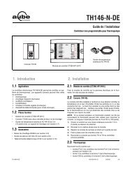
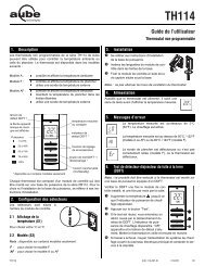
<strong>TH115</strong> A/F/AF<br />
Owner’s Guide<br />
Thank you for choosing the Aube <strong>TH115</strong>, a<br />
programmable thermostat that provides both energy<br />
savings and comfort.<br />
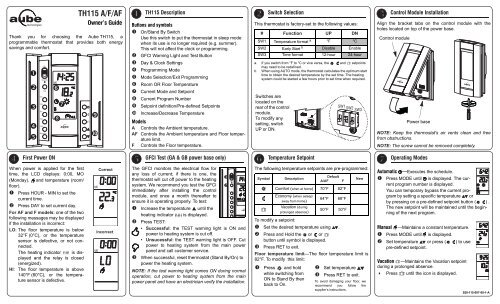
<strong>TH115</strong> Description<br />
Buttons and symbols<br />
On/Stand By Switch<br />
Use this switch to put the thermostat in sleep mode<br />
when its use is no longer required (e.g. summer).<br />
This will not affect the clock or programming.<br />
GFCI Warning Light and Test Button<br />
Day & Clock Settings<br />
Programming Mode<br />
Mode Selection/Exit Programming<br />
Room OR Floor Temperature<br />
Current Mode and Setpoint<br />
Current Program Number<br />
Setpoint definition/Pre-defined Setpoints<br />
Increase/Decrease Temperature<br />
Models<br />
A Controls the Ambient temperature.<br />
AF Controls the Ambient temperature and Floor temperature<br />
limit.<br />
F Controls the Floor temperature.<br />
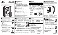
First Power ON GFCI Test (GA & GB power base only)<br />
When power is applied for the first<br />
time, the LCD displays: 0:00, MO<br />
(Monday), and temperature (room/<br />
floor).<br />
Press HOUR - MIN to set the<br />
current time.<br />
Press DAY to set current day.<br />
For AF and F models: one of the two<br />
following messages may be displayed<br />
if the installation is incorrect:<br />
LO: The floor temperature is below<br />
32°F (0°C), or the temperature<br />
sensor is defective, or not connected.<br />
The heating indicator is displayed<br />
and the relay is closed<br />
(energized).<br />
HI: The floor temperature is above<br />
140°F (60°C), or the temperature<br />
sensor is defective.<br />
Correct<br />
Incorrect<br />
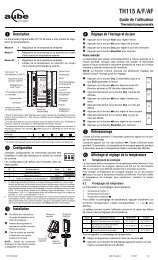
The GFCI monitors the electrical flow for<br />
any loss of current; if there is one, the<br />
thermostat will cut off power to the heating<br />
system. We recommend you test the GFCI<br />
immediately after installing the control<br />
module, and once a month thereafter to<br />
ensure it is operating properly. To test:<br />
Increase the temperature until the<br />
heating indicator is displayed.<br />
Press TEST:<br />
• Successful: the TEST warning light is ON and<br />
power to heating system is cut off.<br />
• Unsucessful: the TEST warning light is OFF. Cut<br />
power to heating system from the main power<br />
panel and call customer service.<br />
When successful, reset thermostat (Stand By/On) to<br />
power the heating system.<br />
NOTE: If the test warning light comes ON during normal<br />
operation, cut power to heating system from the main<br />
power panel and have an electrician verify the installation.<br />
Switch Selection<br />
This thermostat is factory-set to the following values:<br />
# Function UP DN<br />
SW1 Temperature format a °F °C<br />
SW2 Early Start b Disable Enable<br />
SW3 Time format 12-hour 24-hour<br />
a. If you switch from °F to °C or vice versa, the<br />
may need to be redefined.<br />
, and setpoints<br />
b. When using AUTO mode, the thermostat calculates the optimum start<br />
time to obtain the desired temperature by the set time. The heating<br />
system could be started a few hours prior to set time when required.<br />
Switches are<br />
located on the<br />
rear of the control<br />
module.<br />
To modify any<br />
setting, switch<br />
UP or DN.<br />
Temperature Setpoint<br />
The following temperature setpoints are pre-programmed:<br />
Symbol Description<br />
Default<br />
A/AF F<br />
Comfort (when at home) 70°F 82°F<br />
Economy (when asleep/<br />
away from home)<br />
64°F 68°F<br />
Vacation (during<br />
prolonged absence)<br />
50°F 50°F<br />
To modify a setpoint:<br />
Set the desired temperature using .<br />
Press and Hold the or or<br />
button until symbol is displayed.<br />
Press RET to exit.<br />
Floor temperature limit—The floor temperature limit is<br />
82°F. To modify this limit:<br />
Press and hold<br />
while switching from<br />
ON to Stand By then<br />
back to On.<br />
New<br />
Set temperature<br />
Press RET to exit.<br />
To avoid damaging your floor, we<br />
recommend you follow the<br />
supplier’s instructions.<br />
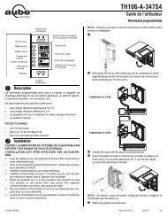
Control Module Installation<br />
Align the bracket tabs on the control module with the<br />
holes located on top of the power base.<br />
Control module<br />
Power base<br />
NOTE: Keep the thermostat's air vents clean and free<br />
from obstructions.<br />
NOTE: The screw cannot be removed completely.<br />
Operating Modes<br />
Automatic —Executes the schedule.<br />
Press MODE until is displayed. The current<br />
program number is displayed.<br />
You can temporary bypass the current program<br />
by setting a specific temperature or<br />
by pressing on a pre-defined setpoint button ( ) .<br />
The new setpoint will be maintained until the beginning<br />
of the next program.<br />
Manual —Maintains a constant temperature.<br />
Press MODE until is displayed.<br />
Set temperature or press ( ) to use<br />
pre-defined setpoint.<br />
Vacation —Maintains the Vacation setpoint<br />
during a prolonged absence.<br />
Press until the icon is displayed.<br />
920-115-007-00-1-A
Pre-programmed Schedule<br />
The <strong>TH115</strong> programmable thermostat is pre-programmed<br />
with the following schedule:<br />
Time you<br />
wake up and<br />
desired<br />
temperature<br />
Time you<br />
leave and<br />
temperature<br />
during your<br />
absence<br />
Time you<br />
return home<br />
and desired<br />
temperature<br />
Time you go<br />
to bed and<br />
overnight<br />
temperature<br />
Programs MO TU WE TH FR SA SU<br />
6:00 6:00 6:00 6:00 6:00 6:00 6:00<br />
8:30 8:30 8:30 8:30 8:30 --:-- --:--<br />
16:00 16:00 16:00 16:00 16:00 --:-- --:--<br />
Temperature Control<br />
23:00 23:00 23:00 23:00 23:00 23:00 23:00<br />
The <strong>TH115</strong> thermostat works differently than conventional<br />
electromechanical thermostats.<br />
It is equipped with a proportional integral adaptive (P.I.A.)<br />
controller which determines heating cycles by analyzing<br />
the temperature behavior history within the room.<br />
The P.I.A. controller reduces temperature variations<br />
providing an accurate temperature control while<br />
increasing user comfort.<br />
The controller determines the amount of power required<br />
by the heating system to maintain the setpoint<br />
temperature.<br />
1 to 20% 21 to 40% 41 to 60% 61 to 80% 81 to 100%<br />
Modify the Schedule<br />
Notes:<br />
You can program up to 4 different programs per day.<br />
Each day can have different programs.<br />
It is sometimes faster to program the same schedule<br />
for the entire week and then to modify the exception<br />
days.<br />
To modify:<br />
Press PGM to access the programming mode<br />
Press DAY to select the day to be programmed (hold<br />
for 3 seconds to select all days of the week).<br />
Press PGM to select the program number.<br />
Press HOUR and MIN to set the time or press<br />
CLEAR to clear the time (--:-- is disregarded).<br />
Repeat steps 2 to 4 for remaining programs.<br />
When completed, press RET to exit mode.<br />
NOTE: After 60 seconds of inactivity, the thermostat will<br />
automatically exit programming mode.<br />
Technical Specifications<br />
Model: <strong>TH115</strong> A / AF / F<br />
Display range: 32°F to 140°F (0°C to 60°C)<br />
Setting range (ambient): 40°F to 86°F (5°C to 30°C)<br />
Setting range (floor limit): 40°F to 104°F (5°C to 40°C)<br />
Pre-programmed temperature setpoints:<br />
Comfort: A/AF: 70°F (21°C) and F: 82°F (28°C)<br />
Economy: A/AF: 64°F (18°C) and F: 68°F (20°C)<br />
Vacation: A/F/AF: 50°F (10°C)<br />
Floor limit:AF: 82°F (28°C)<br />
Accuracy:± 0.9°F (0.5°C)<br />
Storage:-4°F to 120°F (-20°C to 50°C)<br />
Temperature control: Proportional integral adaptive,<br />
15-minute or 15-second heating cycles according to the<br />
application and power base.<br />
Memory backup: In the event of a power failure, an<br />
internal circuit will maintain the programming. Only the<br />
time will have to be set if the power failure is more than<br />
two (2) hours. The thermostat will return to the same<br />
operating mode as set before the power failure.<br />
Custom Grid<br />
Use this blank grid to record your new schedule.<br />
Prog Setpoint MO TU WE TH FR SA SU<br />
Model: A F AF<br />
Temperature display: °F °C<br />
Time display: 12hrs 24hrs<br />
Warranty<br />
AUBE TECHNOLOGIES INC. ONE (1) YEAR LIMITED WARRANTY<br />
This product is guaranteed against workmanship defects for a<br />
one year period following the initial date of purchase. During this<br />
period, AUBE Technologies Inc. will repair or replace, at our<br />
option and without charge, any defective product which has been<br />
used under normal conditions.<br />
The warranty does not cover delivery costs and does not apply to<br />
products poorly installed or randomly damaged following<br />
installation.<br />
This warranty cancels and replaces any other manufacturer's<br />
express or implied warranty as well as any other company<br />
commitment. AUBE Technologies Inc. cannot be held liable for<br />
related or random damages following the installation of this<br />
product.<br />
The defective product as well as the purchase invoice must be<br />
returned to the place of purchase or mailed, prepaid and insured,<br />
to the following address:<br />
Aube Technologies Inc.<br />
705 Montrichard<br />
Saint-Jean-sur-Richelieu, Quebec, Canada J2X 5K8<br />
Remote Input<br />
The <strong>TH115</strong> is equipped with a remote input which allows<br />
connection of a telephone controller (accessory<br />
Aube CT240) or any other remote control system.<br />
When a signal is received through this input, the <strong>TH115</strong><br />
will automatically switch from normal operating mode to<br />
Vacation mode ( ), and vice versa when the signal is<br />
removed.<br />
Activating the Vacation mode<br />
There are two ways to activate the Vacation mode:<br />
From the thermostat, see “Operating Modes” above.<br />
From a telephone (remote location). For details on<br />
how to activate using a telephone, refer to the CT240<br />
Instruction Manual.<br />
WARNING: When the Vacation mode is activated<br />
remotely, it must be deactivated remotely.<br />
If you have any questions concerning the<br />
installation or programming of the <strong>TH115</strong><br />
programmable thermostat, call our technical<br />
support team at:<br />
Phone: Montreal area:(450) 358-4600<br />
Canada / U.S.:1-800-831-AUBE (2823)<br />
Fax: (450) 358-4650<br />
Email: service@aubetech.com<br />
Monday to Friday from 8:30 AM to 5:00 PM EST<br />
For more information on our products, visit us at:<br />
www.aubetech.com<br />
As an ENERGY STAR ® partner, Aube Technologies has<br />
determined that this product meets the ENERGY STAR<br />
guidelines for energy efficiency.<br />
04/08/2003 920-115-007-00-1-A
Applications<br />
The PB112-<strong>024T</strong> power base can be used on any TH11x series<br />
thermostat (with the exception of the TH110 model). This low-voltage<br />
power base operates on 15-minute cycles and can be connected to a<br />
line-voltage load using a relay or directly to a 24-volt device. The<br />
PB112-<strong>024T</strong> is compatible with most relays; however, the following<br />
Aube relays are optimized for use with this power base:<br />
• RT850 solid-state relay (SSR)<br />
• RT850T solid-state relay (SSR) with built-in 24-V transformer<br />
• RC840 electromechanical relay<br />
• RC840T electromechanical relay with built-in 24-V transformer<br />
<br />
One (1) power base<br />
Two (2) plastic anchors<br />
Two (2) mounting screws<br />
<br />
For a new installation, choose a location about 1.5 m (5 ft.)<br />
above the floor.<br />
The thermostat must be installed on an inside wall facing the<br />
heating system (except for floor heating systems).<br />
Avoid locations where there are air drafts (top of staircase, air<br />
outlet), dead air spots (behind a door), direct sunlight or<br />
concealed chimney or stove pipes (except for floor heating<br />
systems).<br />
<br />
Supplied Parts<br />
Installation Guidelines<br />
Installation Procedure<br />
The installation must be carried out by an electrician and comply<br />
with local electrical codes.<br />
Turn off power to the heating system at the main electrical panel<br />
to avoid electrical shock.<br />
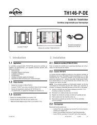
Wire the base according to your application. See typical wiring<br />
diagrams in sections 4.1 to 4.4.<br />
For a floor heating system installation, connect<br />
the floor sensor between the S and R terminals.<br />
Secure the base to the wall using the provided<br />
screws and wall anchors.<br />
Configure the switches located on the control module (if any).<br />
Refer to the user guide.<br />
Install the control module onto the base.<br />
Apply power to the heating system.<br />
Verify the installation by checking that the heating system can be<br />
turned on or off using the thermostat.<br />
1.<br />
2.<br />
3.<br />
4.<br />
4.1 Single SSR with Built-in Transformer<br />
4.2 Multiple SSRs with External Transformer<br />
4.3 Electromechanical Relay with External Transformer<br />
4.4 Hot Water Heater Valve<br />
Maximum load: 0.5 A / 24 VAC<br />
Heating cycle length: 15 minutes<br />
Operating temperature: 32°F to 122°F (0°C to 50°C)<br />
Storage: -4°F to 122°F (-20°C to 50°C)<br />
Size (H•W•D): 124 x 70 x 23 mm (4.89 x 2.76 x 0.91 in)<br />
Wire gauge: 14 to 22 AWG<br />
PB112-<strong>024T</strong> 400-112-000-B 18/1/06 1/1<br />
<br />
Electrical<br />
Panel<br />
Electrical<br />
Panel<br />
Electrical<br />
Panel<br />
Electrical<br />
Panel<br />
Heater<br />
Heater<br />
Blue Red<br />
Black<br />
Black<br />
Red<br />
Black<br />
Red<br />
External 24 V<br />
Transformer<br />
External 24 V<br />
Transformer<br />
Technical Specifications<br />
PB112-<strong>024T</strong><br />
Installation Instructions<br />
24 V Low-Voltage Power Base<br />
Heater<br />
Valve<br />
External 24 V<br />
Transformer<br />
Heater<br />
5.