SUMMARY - Aube Technologies inc.
SUMMARY - Aube Technologies inc.
SUMMARY - Aube Technologies inc.

You also want an ePaper? Increase the reach of your titles
YUMPU automatically turns print PDFs into web optimized ePapers that Google loves.
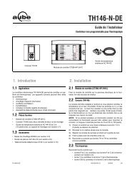
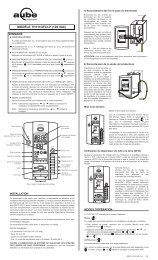
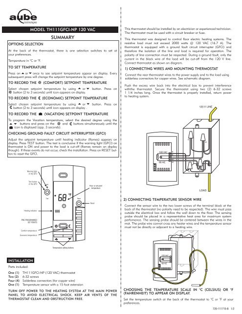
OPTIONS SELECTION<br />
MODEL TH111GFCI-NP 120 VAC<br />
<strong>SUMMARY</strong><br />
At the back of the thermostat, there is one selection switches to set at<br />
your preferences.<br />
Temperature in °C or °F.<br />
TO SET TEMPERATURE<br />
Press on or once to see setpoint temperature appear on display. Every<br />
subsequent press will change the setpoint temperature by one degree.<br />
TO RECORD THE (COMFORT) SETPOINT TEMPERATURE<br />
Select chosen setpoint temperature by using or button. Press on<br />
button (2 to 3 seconds) until icon appears on display.<br />
TO RECORD THE (ECONOMIC) SETPOINT TEMPERATURE<br />
Select chosen setpoint temperature by using or button. Press on<br />
button (2 to 3 seconds) until icon appears on display .<br />
TO RECORD THE (VACATION) SETPOINT TEMPERATURE<br />
To program the Vacation temperature, select the desired degree using the<br />
buttons and press on the and buttons simultaneously until the<br />
icon is displayed (app. 3 seconds).<br />
CHECKING GROUND FAULT CIRCUIT INTERRUPTER (GFCI)<br />
Adjust the setpoint temperature until heating indicator (flames) appears on<br />
display. Press TEST button. The test is conclusive if the warning light (GFCI) on<br />
thermostat is ON and power to the load is cut-off (flames remain on display<br />
though). If these events do not occur, check the installation. Press on RESET button<br />
to reset the GFCI.<br />
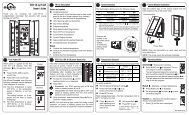
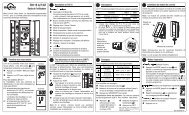
INSTALLATION<br />
Parts <strong>inc</strong>luded:<br />
One (1) TH111GFCI-NP (120 VAC) thermostat<br />
Two (2) 6-32 screws<br />
Four (4) Solderless connectors (for copper wire)<br />
One (1) Temperature sensor with a 15 foot extension<br />
TURN OFF POWER TO THE HEATING SYSTEM AT THE MAIN POWER<br />
PANEL TO AVOID ELECTRICAL SHOCK. KEEP AIR VENTS OF THE<br />
THERMOSTAT CLEAN AND OBSTRUCTION FREE.<br />
This thermostat should be installed by an electrician or experienced technician.<br />
The thermostat must be used with a circuit breaker or fuse.<br />
This thermostat was designed to control floor electric heating systems. The<br />
resistive load must not exceed 2000 watts @ 120 VAC (16.7 A). The<br />
thermostat is equipped with a ground fault circuit interrupter (GFCI) and<br />
therefore the isolation of the line and load is required for operation. The<br />
polarity of line connection must be respected. During a ground fault, only the<br />
current in the black wire of the load will be cut-off from the 120 V line.<br />
Connect thermostat as shown on diagram.<br />
1) CONNECTING WIRES AND MOUNTING THERMOSTAT<br />
Connect the rear thermostat wires to the power supply and to the load using<br />
solderless connectors for copper wires. See schematic diagram.<br />
Push the excess wire back into the electrical box to prevent interference<br />
withthe thermostat. Secure the thermostat using two (2) 6-32 screws<br />
1 1/4 <strong>inc</strong>hes long. Once the thermostat is properly installed, return power<br />
to heating system.<br />
2) CONNECTING TEMPERATURE SENSOR WIRE<br />
Connect the sensor wire to the two lower screws of the terminal block at the<br />
back of the thermostat (no polarity need to be respected). The wire must pass<br />
outside the electrical box and follow the wall down to the floor. The sensing<br />
probe should be placed in a representative heat area for maximum system<br />
perfomance. The sensing probe should be centered between the wires in the<br />
mat. The probe wire cannot cross any heater wires and the temperature sensor<br />
must not be directly or adjacent to a heating wire.<br />
120 VAC<br />
60 HZ<br />
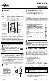
CHOOSING THE TEMPERATURE SCALE IN °C (CELSIUS) OR °F<br />
(FAHRENHEIT) TO APPEAR ON DISPLAY.<br />
Set the temperature switch at the back of the thermostat to °C or °F at your<br />
preferences.<br />
720-111715-B 1/2
POWER UP<br />
To power up thermostat:<br />
CHECKING GROUND FAULT CIRCUIT INTERRUPTER (GFCI)<br />
OPERATION<br />
Adjust the setpoint temperature until<br />
heating indicator ( ) appears on<br />
display. Press TEST button. The test is<br />
conclusive if the warning light (GFCI)<br />
on the thermostat is ON and power to<br />
the load is cut-off. If these events do not<br />
occur, check the installation. Press on<br />
RESET button to reset the GFCI.<br />
If the GFCI test fails:<br />
Check the load wires. The thermostat<br />
must be in heating mode to carry out<br />
the test (heating indicator ON).<br />
The GFCI test should be carried out<br />
monthly. If the test fails, cut off<br />
the electric power to the heating<br />
system and call customer service or<br />
return the thermostat to your supplier<br />
for verification. If the warning light<br />
comes on during normal operation, cut<br />
off power to the heating system and<br />
have an electrician verify the installation.<br />
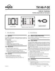
The thermostat has 4 different buttons to control the floor temperature. The<br />
and buttons <strong>inc</strong>rease or decrease the setpoint temperature. The and<br />
buttons are used to store and recall two temperature settings.<br />
• Default values<br />
To erase the recorded setting temperatures ( and ) and replace their values<br />
by the default ones, 28 °C (82 °F) and 18 °C (64 °F) press the button<br />
while pressing and releasing the RESET button. Then release the button.<br />
• Setting a setpoint temperature<br />
When power is applied for the first time,<br />
the display must show the time 00:00,<br />
the floor temperature and the manual<br />
mode icon ( ). Other information<br />
might show up on the display if installation<br />
is defective or does not comply with<br />
the instructions. The warning light (GFI)<br />
must be off.<br />
The message L0 or HI will appear on<br />
the display if the temperature sensor is<br />
defective or the temperature is below 0<br />
°C (32 °F) or higher than 60 °C (140<br />
°F). Also, the heating indicator will be<br />
present on display and the relay will be<br />
closed (current going in the load).<br />
Press once the or button to see the setpoint temperature on display. Every<br />
subsequent press will change the setpoint temperature by one degree.<br />
• Recording setpoint temperature for (COMFORT) , (ECONOMIC) and<br />
(VACATION) settings<br />
By recording the setpoint temperatures you will be able to go from the<br />
setting to the or setting by simply pressing the or button or ( and<br />
) for .<br />
• Recording a setpoint temperature for the (COMFORT) setting<br />
Select chosen setpoint temperature by using and buttons. Keep<br />
pressing on the button (2 to 3 seconds) until icon appears on display.<br />
• Recording a setpoint temperature for the (ECONOMIC) setting<br />
Select chosen setpoint temperature by using and buttons. Keep<br />
pressing on the button (2 to 3 seconds) until icon appears on display.<br />
• Recording a setpoint temperature for the (VACATION) setting<br />
To program the Vacation temperature, select the desired degree using the<br />
buttons and press on the and buttons simultaneously until the<br />
icon is displayed (app. 3 seconds).<br />
NOTE: When the temperature setting used is or or , you can still use<br />
the or buttons to change the setpoint temperature without changing the<br />
recorded temperature.<br />
• Recalling stored setpoint temperatures<br />
Once stored, the setpoint temperatures can be recalled simply by selecting the<br />
or button or both and for setpoint.<br />
CHARACTERISTICS<br />
Model: TH111GFCI-NP (120 VAC)<br />
Supply: 120 VAC, 50/60 Hz<br />
Load: 16.7 A maximum (resistive only)<br />
Power: 2000 watts @ 120 VAC<br />
Ground fault circuit interrupter (GFCI): Class A (5 MA TRIP LEVEL)<br />
Approvals: CSA/C, US<br />
Display range: 0 to 60 ºC (32 °F to 140 ºF)<br />
Setting range: 5 °C to 40 ºC (40 °F to 104 ºF)<br />
Default setting: 28 °C (82 °F)<br />
Default setting: 18 °C (64 °F)<br />
Storage: -20 °C to 50 ºC (-4 °F to 120 ºF)<br />
Temperature regulation: 1 ºC (2 °F)<br />
Precision: ± 0.5 ºC (1 °F) (2000 W)<br />
WARRANTY<br />
AUBE TECHNOLOGIES INC. ONE (1) YEAR LIMITED WARRANTY<br />
This product is warranted against material defects and workmanship in<br />
normal use for a period of one year, from the date of the original purchase from<br />
authorized dealers. During this period, AUBE technologies <strong>inc</strong>. will repair or<br />
replace the product with a new or of equivalent quality at AUBE'S option,<br />
without charge, any product proven defective in normal use.<br />
Warranty does not cover transportation costs. Nor does it cover a product<br />
subjected to misuse or accidental damage. This warranty does not cover the cost<br />
of installation, removal or reinstallation.<br />
This limited warranty is in lieu of all other warranties, obligations or liabilities<br />
expressed or implied by the company. In no event shall AUBE technologies <strong>inc</strong>.<br />
be liable for consequential or <strong>inc</strong>idental damages resulting from<br />
installation of this product. Some states or prov<strong>inc</strong>es do not allow limitations on<br />
how long an implied warranty lasts, or the exclusion or limitation of<br />
<strong>inc</strong>idental or consequential damages, so the above exclusions or limitations may<br />
not apply to you.This warranty gives you specific legal rights and you may also<br />
have other rights which vary from state to state.<br />
The defective product and the original sale receipt must be returned to the<br />
original dealer or shipped pre-paid, insured and addressed to:<br />
•<strong>Aube</strong> technologies <strong>inc</strong>. • Customer Service • 705, Av. Montrichard<br />
• Iberville (Quebec) • J2X 5K8<br />
If you have any questions concerning the installation or programming of this<br />
product, please call our technical assistance at (450) 358-4600 for the Montreal<br />
area or 1-800-831-AUBE for outside area, Monday to Friday between<br />
8:30 AM and 5:00 PM Eastern time.<br />
09/03/01 720-111715-B 2/2