
You also want an ePaper? Increase the reach of your titles
YUMPU automatically turns print PDFs into web optimized ePapers that Google loves.
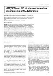
IOP PUBLISHING JOURNAL OF MICROMECHANICS AND MICROENGINEERING<br />
J. Micromech. Microeng. 18 (2008) 045004 (13pp) doi:10.1088/0960-1317/18/4/045004<br />
<strong>Plasma</strong> <strong>removal</strong> <strong>of</strong> <strong>Parylene</strong> C<br />
Ellis Meng 1 , Po-Ying Li 2 and Yu-Chong Tai 3<br />
1 Department <strong>of</strong> Biomedical Engineering, University <strong>of</strong> Southern California, 1042 Downey Way,<br />
DRB-140 Los Angeles, CA 90089-1111, USA<br />
2 Department <strong>of</strong> Electrical Engineering, University <strong>of</strong> Southern California, 3737 Watt Way,<br />
PHE-604 Los Angeles, CA 90089-0271, USA<br />
3 Department <strong>of</strong> Electrical Engineering, California Institute <strong>of</strong> Technology, 1200 E California Blvd.,<br />
Pasadena, CA 91125, USA<br />
E-mail: ellis.meng@usc.edu<br />
Received 20 November 2007, in final form 13 January 2008<br />
Published 22 February 2008<br />
Online at stacks.iop.org/JMM/18/045004<br />
Abstract<br />
<strong>Parylene</strong> C, an emerging material in microelectromechanical systems, is <strong>of</strong> particular interest<br />
in biomedical and lab-on-a-chip applications where stable, chemically inert surfaces are<br />
desired. Practical implementation <strong>of</strong> <strong>Parylene</strong> C as a structural material requires the<br />
development <strong>of</strong> micropatterning techniques for its selective <strong>removal</strong>. Dry etching methods are<br />
currently the most suitable for batch processing <strong>of</strong> <strong>Parylene</strong> structures. A performance<br />
comparison <strong>of</strong> three different modes <strong>of</strong> <strong>Parylene</strong> C plasma etching was conducted using<br />
oxygen as the primary reactive species. <strong>Plasma</strong>, reactive ion and deep reactive ion etching<br />
techniques were explored. In addition, a new switched chemistry process with alternating<br />
cycles <strong>of</strong> fluoropolymer deposition and oxygen plasma etching was examined to produce<br />
structures with vertical sidewalls. Vertical etch rates, lateral etch rates, anisotropy and sidewall<br />
angles were characterized for each <strong>of</strong> the methods. This detailed characterization was enabled<br />
by the application <strong>of</strong> replica casting to obtain cross sections <strong>of</strong> etched structures in a<br />
non-destructive manner. Application <strong>of</strong> the developed etch recipes to the fabrication <strong>of</strong><br />
complex <strong>Parylene</strong> C microstructures is also discussed.<br />
(Some figures in this article are in colour only in the electronic version)<br />
1. Introduction<br />
<strong>Parylene</strong>, or poly (p-xylylene), is one <strong>of</strong> the most well-known<br />
chemical vapor deposited (CVD) thin film polymers. It is<br />
used in a wide range <strong>of</strong> applications, particularly as a coating<br />
for biomedical implants and microelectronics. Its desirable<br />
properties include chemical inertness, conformal coating and<br />
excellent barrier properties [1]. Originally discovered in<br />
1947 by Swarc, <strong>Parylene</strong>s were not commercialized by Union<br />
Carbide until 1965 following the development <strong>of</strong> a CVD<br />
polymerization process by Gorham [2–4]. Although over<br />
twenty types <strong>of</strong> <strong>Parylene</strong> have been developed, only three<br />
are commonly available: <strong>Parylene</strong>s N, C and D (figure 1).<br />
With increasing interest in <strong>Parylene</strong>s, newer commercial<br />
products have recently been introduced including, <strong>Parylene</strong> HT<br />
(Specialty Coating Systems, Indianapolis, IN), a fluorinated<br />
version <strong>of</strong> the polymer, and diX A and AM (Kishimoto Sangyo<br />
Co., Ltd, Japan), having amino groups attached to the benzene<br />
rings.<br />
<strong>Parylene</strong> C (poly(monochloro-p-xylylene)) has a long<br />
history <strong>of</strong> use in the medical industry as a coating for<br />
stents, cardiac assist devices, surgical tools, electronics and<br />
catheters [5]. The use <strong>of</strong> <strong>Parylene</strong> C as a structural material<br />
in microelectromechanical systems (MEMS) devices and in<br />
particular bioMEMS and micr<strong>of</strong>luidics has gained traction<br />
[6–10]. Among the many polymers used as structural<br />
materials, <strong>Parylene</strong> C is an increasingly popular choice due to<br />
its deposition method, low process temperature, transparency<br />
and compatibility with standard micr<strong>of</strong>abrication processes<br />
[11]. It is possible to perform multilayer processing <strong>of</strong><br />
<strong>Parylene</strong> films to produce complex structures and devices.<br />
<strong>Parylene</strong> C is a USP (United States Pharmacopeia)<br />
Class VI polymer. This designation is the highest level <strong>of</strong><br />
biocompatibility possible for polymers permitting its use in<br />
applications where long-term implantation is required. Its<br />
biocompatibility, biostability, low cytotoxicity and resistance<br />
against hydrolytic degradation [1, 12, 13] have resulted<br />
in increasing popularity <strong>of</strong> <strong>Parylene</strong> C in micro- and<br />
0960-1317/08/045004+13$30.00 1 © 2008 IOP Publishing Ltd Printed in the UK
J. Micromech. Microeng. 18 (2008) 045004 EMenget al<br />
nano-fabricated devices for micr<strong>of</strong>luidic and bioMEMS<br />
applications. For example, <strong>Parylene</strong> C-based devices have<br />
been demonstrated as platforms for neuronal growth [14–16]<br />
and in implantable neuronal probes [17]. Furthermore, new<br />
developments on the functionalization <strong>of</strong> <strong>Parylene</strong> surfaces<br />
may expand its use in biomedical applications [18–20].<br />
Pattern transfer <strong>of</strong> masks into <strong>Parylene</strong> C films is a<br />
critical enabling step in <strong>Parylene</strong> micr<strong>of</strong>abrication technology.<br />
Dry plasma-based etching techniques are likely the most<br />
suitable means for achieving fine features in <strong>Parylene</strong> C<br />
films. The characterization <strong>of</strong> <strong>Parylene</strong> C <strong>removal</strong> by oxygenbased<br />
plasmas was investigated for three plasma etching<br />
modes: plasma, reactive ion and deep reactive ion etching.<br />
In particular, the focus <strong>of</strong> this study was on identifying<br />
process parameters that will enable anisotropic etching toward<br />
achieving high aspect ratio (HAR) structures desirable for<br />
MEMS applications. Removal rates for the photoresist<br />
masking layer were also monitored.<br />
2. Patterning <strong>Parylene</strong><br />
2.1. Chemical <strong>removal</strong><br />
A key feature <strong>of</strong> <strong>Parylene</strong> is chemical inertness which<br />
complicates its chemical <strong>removal</strong>. Below the melting<br />
point, <strong>Parylene</strong> is resistant to dissolution by solvents. At<br />
temperatures above 150 ◦ C, it is possible to remove <strong>Parylene</strong> in<br />
either chloronaphthelene or benzolyl benzoate [21]. However,<br />
this method is not compatible with most commonly used<br />
lithographic processes. The highly conformal natural <strong>of</strong><br />
<strong>Parylene</strong> films prevents patterning via lift-<strong>of</strong>f processes.<br />
2.2. <strong>Plasma</strong> <strong>removal</strong><br />
Oxygen (O2) plasmas are used to etch many polymers but the<br />
specific mechanisms for this <strong>removal</strong> are not well understood.<br />
Polymer etching in pure oxygen plasmas is linked to the<br />
presence <strong>of</strong> atomic O; etching enhancement is associated with<br />
an increase in atomic O by increase <strong>of</strong> dissociation, reduction<br />
<strong>of</strong> losses due to recombination, and increase <strong>of</strong> O atom flux<br />
from the plasma to the sample [22]. Increases in electron<br />
density or electron energy can increase O2 dissociation.<br />
Figure 1. Commercially available poly (p-xylylene) types.<br />
2<br />
<strong>Parylene</strong> is readily removed in oxygen-based plasmas and<br />
the possible etching reactions that govern <strong>Parylene</strong> <strong>removal</strong><br />
have been suggested [23, 24]. The etching mechanism for<br />
<strong>Parylene</strong> C is thought to be similar to that <strong>of</strong> <strong>Parylene</strong> N<br />
which is different only by the absence <strong>of</strong> a chlorine atom.<br />
<strong>Plasma</strong> <strong>removal</strong> <strong>of</strong> <strong>Parylene</strong> N is attributed to the opening <strong>of</strong><br />
the benzene ring which is necessary in etching <strong>of</strong> aromatic<br />
polymers. This process is thought to occur as follows. First,<br />
hydrogen is abstracted by an oxygen radical from the ethyl<br />
carbons between the benzene rings in the polymer chain and a<br />
hydroxyl radical is formed. Then the exposed reactive site is<br />
subjected to molecular or atomic oxygen absorption to form<br />
an unstable peroxy radical. Rearrangement <strong>of</strong> the unstable<br />
species can then result in the formation <strong>of</strong> volatile carbon<br />
monoxide (for atomic oxygen adsorption) or carbon dioxide<br />
(for molecular oxygen adsorption). Further oxygen attack on<br />
the radical site results in ring opening.<br />
While the mechanisms governing <strong>Parylene</strong> C <strong>removal</strong> are<br />
likely similar to those for <strong>Parylene</strong> N, the presence <strong>of</strong> a chlorine<br />
atom on the ring reduces the available reactive carbon sites by<br />
one. If ring opening is the rate limiting step in <strong>Parylene</strong><br />
etching, then the reduction in reactive sites may explain the<br />
observed reduction in <strong>Parylene</strong> C etch rate compared to that<br />
<strong>of</strong> <strong>Parylene</strong> N by ∼17% [23].<br />
<strong>Parylene</strong> etching has been demonstrated in multiple<br />
modes including plasma etching [19, 25, 26], reactive ion<br />
beam etching (RIBE) [27], reactive ion etching (RIE) [28, 29]<br />
and high-density plasma etching [30]. However, no attempt<br />
has been made to optimize anisotropy or employ sidewall<br />
passivation to produce high aspect ratio structures. Yeh<br />
demonstrated patterning fine features (∼2.5 µm) in thin films<br />
but observed an etch selectivity near unity between <strong>Parylene</strong><br />
C and photoresist by RIE [29]. Vertical pr<strong>of</strong>iles were achieved<br />
when using metal or oxide masks and under conditions <strong>of</strong> low<br />
pressure, low power and a biased substrate. However, etched<br />
features exhibited significant roughness and the presence <strong>of</strong><br />
dense micrograss structures due to redeposition <strong>of</strong> the hard<br />
mask [28, 29]. <strong>Parylene</strong> <strong>removal</strong> by RIBE achieved smoother<br />
surfaces but at the expense <strong>of</strong> greatly reduced etch rates (∼10’s<br />
<strong>of</strong> ˚Amin −1 compared to ∼10 2 –10 3 ˚Amin −1 )[27].<br />
Recently sidewall passivation and inductively coupled<br />
plasma sources have been explored to achieve anisotropic
J. Micromech. Microeng. 18 (2008) 045004 EMenget al<br />
(a)<br />
(b)<br />
(c)<br />
(d)<br />
(e)<br />
Figure 2. Illustrations (a)–(d) <strong>of</strong> the process used to fabricate silicone rubber replicas <strong>of</strong> etched <strong>Parylene</strong> C features and (e) the replica<br />
mounting method in preparation for SEM viewing. (f ) SEM image <strong>of</strong> a sectioned silicone rubber replica that has been Au sputter-coated.<br />
(a) (b) (c)<br />
Figure 3. Au-coated cross sections <strong>of</strong> PDMS replicas <strong>of</strong> 10 µm line features etched using (a) plasma etching, (b) RIE and (c) DRIE modes.<br />
The scale bar in each image measures 5 µm. Cracking <strong>of</strong> the Au conductive coating is evident.<br />
etching <strong>of</strong> polymers. Zahn achieved aspect ratios up to 20:1 for<br />
deep reactive ion etching (DRIE) <strong>of</strong> polymethylmethacrylate<br />
(PMMA) by using a switched chemistry etching technique<br />
inspired by the Bosch process for silicon <strong>removal</strong> [31].<br />
SiO2 masks and an inductively coupled plasma source were<br />
used to create vertical <strong>Parylene</strong> N sidewalls in high-density<br />
oxygen-based plasmas (Ar/O2) [30]. The anisotropy was in<br />
part attributed to the sidewall passivation by redeposition <strong>of</strong><br />
oxygen-deficient etch products which prevent lateral erosion<br />
due to reflection <strong>of</strong> atomic and molecular oxygen. Anisotropy<br />
was further improved by increasing the substrate bias which is<br />
consistent with the results <strong>of</strong> earlier studies.<br />
2.3. Alternative methods<br />
Alternative methods for the selective deposition and <strong>removal</strong> <strong>of</strong><br />
<strong>Parylene</strong> insulation layers on implantable electrodes have been<br />
reported. The thickness <strong>of</strong> deposited <strong>Parylene</strong> is a function <strong>of</strong><br />
substrate temperature [32, 33] so biased resistors were used<br />
to generate a localized heat gradient that prevented deposition<br />
in regions held above 70 ◦ C[34]. <strong>Parylene</strong> has been used<br />
as an insulation coating for microelectrodes used in neural<br />
recordings. Selective <strong>removal</strong> by ultraviolet laser ablation<br />
[35, 36] and manual mechanical <strong>removal</strong> on wire<br />
microelectrodes [37] has also been reported.<br />
More recently, thermal imprint patterning in Ni molds<br />
and micromolding techniques have also been investigated.<br />
Thermal imprinting achieved 25 µm high 10 µm wide<br />
line features in 30 µm thick parylene, but required high<br />
temperature processing at 250 ◦ C to enable accurate pattern<br />
replication [38]. Micromolding <strong>of</strong> <strong>Parylene</strong> films to a<br />
3<br />
( f )<br />
Figure 4. Illustration showing parameters measured to obtain the<br />
vertical etch rate, lateral etch rate and sidewall angle.<br />
patterned mold and then thermocompression bonding with a<br />
second <strong>Parylene</strong> film was developed as an alternative to surface<br />
micromachining <strong>of</strong> microchannels [39, 40].<br />
3. Experimental methods<br />
3.1. Preparation <strong>of</strong> etched <strong>Parylene</strong> C coupons<br />
Four inch silicon wafers were treated with A-174 silane<br />
adhesion promoter (Specialty Coating Systems, Indianapolis,<br />
IN). Next, the back side <strong>of</strong> each wafer was covered with a<br />
dicing saw tape (Nitto Denko Corporation, Osaka, Japan) to<br />
restrict <strong>Parylene</strong> coating to only the front side. 10 µm <strong>of</strong><br />
<strong>Parylene</strong> C (Specialty Coating Systems, Indianapolis, IN) was<br />
deposited (PDS 2010 Labcoter, Specialty Coating Systems,<br />
Indianapolis, IN). The <strong>Parylene</strong> coating was gently scored with<br />
a sharp razor and the dicing saw tape was carefully removed<br />
from the back side. After priming with hexamethyldisilazane<br />
(HMDS), 14 µm <strong>of</strong> photoresist (AZ 4620, AZ Electronic<br />
Materials, Branchburg, NJ) was applied by spin coating<br />
(1 krpm for 40 s) and then patterned with an etching calibration<br />
pattern consisting <strong>of</strong> lines, trenches and other geometrical<br />
features.
J. Micromech. Microeng. 18 (2008) 045004 EMenget al<br />
(a) (b)<br />
(c) (d)<br />
Figure 5. Etch data for <strong>Parylene</strong> C samples (n = 4) processed by plasma etching using oxygen plasma: (a) vertical etch rate, (b) lateral etch<br />
rate, (c) anisotropy and (d) the measured sidewall angle. Process pressure (200 and 400 mTorr) and power (100, 200, 300 and 400 W) were<br />
varied.<br />
Table 1. Process parameters examined in each <strong>of</strong> the etching modes.<br />
<strong>Plasma</strong> Reactive ion Deep reactive<br />
etching etching ion etching<br />
Power Power Power<br />
Pressure Pressure Pressure<br />
O2 flow rate O2 flow rate<br />
Addition <strong>of</strong> Ar<br />
Sidewall passivation with C4F8<br />
Etch step time<br />
Patterned test coupons measuring 20 mm × 10 mm<br />
and containing two identical calibration dies were carefully<br />
separated from wafers by manually scribing and breaking<br />
each piece. Test coupons were etched for a fixed time <strong>of</strong><br />
10 min under varying process conditions in plasma etching<br />
(PEII-A, Technics <strong>Plasma</strong>, Kirchheim, Germany), RIE (1000<br />
TP/CC, SemiGroup Texas, LLC, McKinney, Texas), and<br />
DRIE (<strong>Plasma</strong>Therm SLR-770B, Unaxis Corporation, St<br />
Petersburg, FL) equipment. Process pressure, gas flow,<br />
power and etching chemistries were varied. DRIE mode<br />
enabled switched chemistry etching in which samples were<br />
exposed to alternating cycles <strong>of</strong> (1) deposition <strong>of</strong> a C4F8-based<br />
Teflon-like sidewall passivation layer and (2) etching in O2<br />
plasma. Deposition <strong>of</strong> the fluoropolymer layer protected the<br />
sidewalls from lateral etching. Table 1 summarizes the process<br />
4<br />
parameters examined in each etching mode. Table 2 shows in<br />
detail the process recipes used in DRIE <strong>of</strong> <strong>Parylene</strong> C. One<br />
test coupon was processed for each condition examined. For<br />
plasma etching, 8 different process conditions were studied.<br />
RIE and DRIE studies involved 18 and 21 different process<br />
conditions. In total, 47 test coupons were processed (94 dies,<br />
2 dies each process condition).<br />
3.2. Photoresist mask etch rate measurement<br />
The step heights <strong>of</strong> the etched structures (photoresist +<br />
<strong>Parylene</strong>) were measured using a surface pr<strong>of</strong>ilometer (Alpha-<br />
Step 200, KLA-Tencor, San Jose, CA). Then the two dies in<br />
each test coupon were separated manually by scribing and<br />
breaking. The remaining photoresist was removed on one <strong>of</strong><br />
the dies. The step heights <strong>of</strong> the remaining <strong>Parylene</strong> structures<br />
were measured. The obtained step height data were used to<br />
calculate the vertical etch rates <strong>of</strong> the photoresist masking<br />
layer.<br />
3.3. Preparation <strong>of</strong> SEM samples by replica molding<br />
Accurate determination <strong>of</strong> vertical etch rate, lateral etch<br />
rate, sidewall angle and the etch pr<strong>of</strong>ile is possible only<br />
by examining cross-section samples under scanning electron<br />
microscopy (SEM). Preparation <strong>of</strong> <strong>Parylene</strong> samples for SEM
J. Micromech. Microeng. 18 (2008) 045004 EMenget al<br />
(a) (b)<br />
(c) (d)<br />
Figure 6. Etch data for <strong>Parylene</strong> C samples (n = 4) processed by RIE using an oxygen plasma at 200 W: (a) vertical etch rate, (b) lateral<br />
etch rate, (c) anisotropy and (d) the measured sidewall angle. Process pressure (150, 200 and 250 mTorr) and oxygen flow rate (40, 80 and<br />
120 sccm) were varied.<br />
Table 2. Parameters for DRIE recipes.<br />
Recipe parameters Oxygen only Oxygen + argon Switched chemistry<br />
O2 flow rate (sccm) 20, 60, 100 20, 60, 100 20, 60, 100<br />
C4F8 flow rate (sccm) 0 0 35<br />
Ar flow rate (sccm) 0 0, 50, 100 (40, during the deposition step)<br />
Etch coil power (W) 400, 800 800 800<br />
Etch platen power (W) 20 20 20<br />
Deposition coil power (W) N/A N/A 825<br />
Deposition platen power N/A N/A 1<br />
Etch step time (s) 600 600 10, 20<br />
Deposition time (s) N/A N/A 3<br />
Etch process pressure (mTorr) 13, 23 23 23<br />
Deposition process pressure (mTorr) N/A N/A 22<br />
is particularly challenging. In general, cleaving polymer<br />
films to produce cross-sections requires special techniques,<br />
such as focused ion beam (FIB) or cryogenic freezing, to<br />
prevent tearing or deformation <strong>of</strong> fine features. However,<br />
consistent cross-sections <strong>of</strong> <strong>Parylene</strong> films are difficult to<br />
obtain by cleaving frozen samples and FIB tools are both<br />
rare and expensive. Accurate negative reproductions <strong>of</strong><br />
delicate etched features can be obtained by replication,<br />
a method commonly employed in polymer microscopy<br />
[41]. Application <strong>of</strong> replica casting allowed preparation<br />
<strong>of</strong> cross sections <strong>of</strong> etched structures in a non-destructive<br />
manner.<br />
5<br />
The replication process is summarized in figure 2.<br />
Silicone rubber (Sylgard 184, Dow Corning, Midland, MI)<br />
was prepared (AR-250 Hybrid Mixer, Thinky Corp., Tokyo,<br />
Japan) with a 10:1 base-to-curing-agent ratio. The prepolymer<br />
mix was poured onto the etched test coupons (figure 2(a)),<br />
degassed (V0914 vacuum oven, Lindberg/Blue, Asheville,<br />
NC), and cured at 65 ◦ C for 1 h (figure 2(b)). Each replica was<br />
peeled from the etched master and cut into a suitable size for<br />
SEM imaging (figure 2(c)). Replicas were then cross sectioned<br />
with a razor blade (figure 2(d)) and sputter-coated with Au,<br />
making the surface conductive for SEM viewing (figures 2(e)<br />
and (f )).
J. Micromech. Microeng. 18 (2008) 045004 EMenget al<br />
(a) (b)<br />
(c) (d)<br />
Figure 7. Etch data for <strong>Parylene</strong> C samples (n = 4) processed by RIE using oxygen plasma at 400 W: (a) vertical etch rate, (b) lateral etch<br />
rate, (c) anisotropy and (d) the measured sidewall angle. Process pressure (150, 200 and 250 mTorr) and oxygen flow rate (40, 80 and 120<br />
sccm) were varied.<br />
3.4. <strong>Parylene</strong> C etch rate measurement<br />
Replications <strong>of</strong> etched 10 µm line features for each etching<br />
mode are shown in figure 3. The cracks in the image are<br />
present in the sputter-coated Au layer and are possibly due to<br />
slight expansion in the silicone rubber under vacuum. ImageJ<br />
(v.1.34, National Institutes <strong>of</strong> Health) s<strong>of</strong>tware facilitated the<br />
measurement <strong>of</strong> individual feature dimensions used in the<br />
calculation <strong>of</strong> vertical etch rate, lateral etch rate and anisotropy.<br />
The sidewall angle <strong>of</strong> etched lines was also obtained from<br />
acquired SEM images using ImageJ. Four cross sections <strong>of</strong><br />
10 µm line features were measured to obtain these parameters.<br />
The definitions for the measurements used to calculate each<br />
parameter are defined in figure 4.<br />
Vertical etch rate, Rvertical,isdefinedas<br />
Rvertical = h<br />
(1)<br />
t<br />
where h is the etched depth and t is the etch duration (10 min<br />
in all cases). Lateral etch rate, Rlateral,isdefinedas<br />
(10 µm − a)/2<br />
Rlateral = (2)<br />
t<br />
where a is the width <strong>of</strong> the top <strong>of</strong> the etched line. The starting<br />
line width was 10 µm for all cases. Etch anisotropy, A, can by<br />
quantified by using the following definition [42]:<br />
A = 1 − Rlateral<br />
. (3)<br />
Rvertical<br />
6<br />
A vertical pr<strong>of</strong>ile corresponds to A = 1 and occurs when there<br />
is no undercutting. The sidewall angle, θ, is measured as<br />
indicated in figure 4.<br />
4. Results and discussion<br />
The lateral and vertical etch rates, anisotropy, and sidewall<br />
angle <strong>of</strong> 10 µm wide <strong>Parylene</strong> C lines obtained by oxygen<br />
plasma <strong>removal</strong> in each etching mode as functions <strong>of</strong> applied<br />
power and process pressure were determined (figures 5–8). In<br />
the RIE and DRIE modes, the effect <strong>of</strong> varying the oxygen<br />
flow rate was also examined. All <strong>of</strong> the data presented in these<br />
plots are displayed as mean ± SE where n = 4. Representative<br />
SEM images for <strong>Parylene</strong> C <strong>removal</strong> by oxygen-only plasmas<br />
in each <strong>of</strong> the different etching systems are presented in<br />
figure 9.<br />
As expected for plasma etching, the vertical and lateral<br />
etch rates were similar; in some cases, the lateral etch rate was<br />
greater than the vertical etch rate (figure 5). The etched pr<strong>of</strong>iles<br />
<strong>of</strong> <strong>Parylene</strong> C lines were decidedly isotropic. Changing the<br />
process pressure did little to affect the vertical etch rate but<br />
seemed to provide a slight improvement in sidewall angle. At<br />
400 mTorr and 200 W, the etched lines were damaged and only<br />
two line samples were recovered. Since the sample size was
J. Micromech. Microeng. 18 (2008) 045004 EMenget al<br />
(a) (b)<br />
(c) (d )<br />
Figure 8. Etch data for <strong>Parylene</strong> C samples (n = 4) processed by DRIE using oxygen plasma: (a) vertical etch rate, (b) lateral etch rate, (c)<br />
anisotropy and (d) the measured sidewall angle. Process pressure (13 and 23 mTorr), oxygen flow rate (20, 60 and 100 sccm) and power<br />
(400 and 800 W) were varied.<br />
insufficient to perform statistical analysis, the data point was<br />
omitted.<br />
For <strong>Parylene</strong> C coupons etched by RIE, the vertical etch<br />
rate increased with increasing power (figures 6, 7). At 200 W,<br />
the vertical etch rate decreased as oxygen flow rate and process<br />
pressure were increased; whereas at 400 W, the vertical etch<br />
rate remained relatively constant. The lateral etch rate was<br />
similar at 200 and 400 W. At 200 W, however, the lateral etch<br />
rate increased as oxygen flow rate and process were increased.<br />
The magnitude <strong>of</strong> the lateral etch rate was similar to that <strong>of</strong><br />
the vertical etch rate for these conditions. At higher power<br />
(400 W), the ratio <strong>of</strong> the vertical-to-lateral etch rate was higher<br />
resulting in better anisotropy and improved sidewall angles.<br />
Interestingly, although higher anisotropy (∼0.8) was<br />
achieved for the 80 sccm O2 setpoint in the 200 W case, the<br />
corresponding sidewall angle was only ∼30 ◦ . Such conditions<br />
are possible upon a closer inspection <strong>of</strong> the definitions for these<br />
parameters given in figure 4 and equations (1)–(3). The lateral<br />
etch rate calculation assumes that the starting photoresist<br />
mask measured exactly 10 µm in width. Since the actual<br />
measurement site varies slightly from sample to sample, the<br />
corresponding mask dimension cannot be measured precisely<br />
prior to etching. Also, the replica molding technique requires<br />
smooth sidewalls making it difficult to monitor mask erosion<br />
following etching. In all cases, the photoresist masking layer<br />
7<br />
was removed prior to replication <strong>of</strong> etched line features for<br />
SEM viewing. In the particular case under examination here,<br />
the difference between anisotropy and sidewall angle implies<br />
either reduced vertical etching efficiency near the sidewalls<br />
or the width <strong>of</strong> the starting photoresist mask may have been<br />
slightly larger than 10 µm.<br />
Higher vertical etch rates (>0.5 µm min −1 ) were<br />
possible with DRIE using an oxygen-only plasma but with<br />
corresponding increases in lateral etch rates as well. The<br />
vertical and lateral etch rates tended to increase with increasing<br />
power and process pressure and decreasing oxygen flow rate<br />
(figure 8). At 800 W, the ratio <strong>of</strong> the vertical-to-lateral<br />
etch rate was greater, yielding clear advantages in anisotropy<br />
and sidewall angle over the 400 W case. In comparison to<br />
RIE, the DRIE mode yielded slightly better sidewall angles.<br />
Surprisingly, the vertical etch rate was not significantly greater<br />
than the lateral etch rate at 400 W. Given the operating<br />
mechanism behind DRIE, this trend was not expected and<br />
further experiments are required to fully understand the nature<br />
<strong>of</strong> this effect.<br />
The etch rate for polymers generally increases with<br />
oxygen gas pressure (flow limited regime) and decreases for<br />
higher pressure where the active species can be removed<br />
before it can react [23]. It has also been suggested that<br />
the maximum etch rate corresponds to the maximum oxygen
J. Micromech. Microeng. 18 (2008) 045004 EMenget al<br />
(a) (b) (c)<br />
Figure 9. Representative SEM images <strong>of</strong> etched <strong>Parylene</strong> C lines produced by (a) plasma etching (400 mTorr, 400 W), (b) RIE (150 mTorr,<br />
20 sccm, 400 W) and (c) DRIE (23 mTorr, 100 sccm, 800 W) with oxygen-only plasmas. The photoresist masking layer was removed and<br />
samples were coated in Au to prevent charging; (a) and (c) were reprinted with permission (© 2005 IEEE) [43].<br />
(a) (b)<br />
(c) (d)<br />
Figure 10. Etch data for <strong>Parylene</strong> C samples processed by DRIE using oxygen and argon plasma: (a) vertical etch rate, (b) lateral etch rate,<br />
(c) anisotropy and (d) the measured sidewall angle. The oxygen flow rate (20, 60 and 100 sccm) and argon flow rate (0, 50 and 100 sccm)<br />
were varied. The process pressure was 23 mTorr and the applied power was 800 W.<br />
radical concentration and that further increases in gas pressure<br />
are accompanied by an increase in the oxygen recombination<br />
and reduction in oxygen radical concentration [24]. Hence, it<br />
is reasonable that the addition <strong>of</strong> CF4 to the oxygen plasma<br />
has been shown to enhance <strong>Parylene</strong> etching [28]. A similar<br />
technique is used in photoresist etching in which few percent<br />
CF4 is added to the oxygen plasma. The addition <strong>of</strong> fluorine<br />
containing gases such as CF4 and SF6 is thought to increase<br />
oxygen atom concentration compared to a pure O2 plasma<br />
and increase etch rate or to produce HF and leave unsaturated<br />
8<br />
or radical sites for oxygen atom attack [22, 44, 45]. Other<br />
gases may also improve <strong>Parylene</strong> etching; the addition <strong>of</strong> N2<br />
to oxygen plasma contributes to increase O atom generation<br />
and the addition <strong>of</strong> He increases electron densities and energies<br />
in the plasma [22]. In the studies presented here, additional<br />
gas lines were not available on all the process tools for further<br />
investigation <strong>of</strong> the described effects.<br />
In the DRIE mode, the effects <strong>of</strong> adding argon to the<br />
oxygen plasma and the use <strong>of</strong> switched chemistry etching were<br />
also examined. The lateral and vertical etch rates, anisotropy,
J. Micromech. Microeng. 18 (2008) 045004 EMenget al<br />
(a) (b)<br />
(c) (d)<br />
Figure 11. Etch rates for <strong>Parylene</strong> C samples processed by DRIE using switched chemistry etching: (a) vertical etch rate, (b) lateral etch<br />
rate, (c) anisotropy and (d) the measured sidewall angle. The oxygen flow rate (20, 40 and 100 sccm) was varied and two different etch step<br />
durations (10 and 20 s) were examined. The process pressure was 23 mTorr and the applied power was 800 W.<br />
(a) (b)<br />
Figure 12. Representative SEM images <strong>of</strong> DRIE <strong>Parylene</strong> C lines produced by (a) oxygen and argon plasma (23 mTorr, 20 sccm O2,50<br />
sccm Ar, 800 W) and (b) switched chemistry etching (23, mTorr, 20 sccm O2, 800 W, 10 s etch step). The photoresist masking layer has<br />
been removed and samples coated in Au to prevent charging. The images were reprinted with permission (© 2005 IEEE) [43].<br />
and sidewall angle <strong>of</strong> 10 µm wide <strong>Parylene</strong> C lines obtained<br />
as a function <strong>of</strong> oxygen and argon flow rate are shown in<br />
figure 10. For switched chemistry etching, the data are<br />
displayed in figure 11 as a function <strong>of</strong> oxygen flow rate<br />
and for two different etch step times. A total <strong>of</strong> 30 and 60<br />
etch loops were performed under switched chemistry etching<br />
corresponding to etch step times <strong>of</strong> 10 and 20 s, respectively,<br />
for a total fixed etch time <strong>of</strong> 10 min. The deposition step<br />
time was held constant at 3 s. The representative SEM images<br />
<strong>of</strong> etched <strong>Parylene</strong> C lines in these process conditions are<br />
presented in figure 12.<br />
9<br />
Ion bombardment can reportedly lower the activation<br />
energy for etching some polymers [22]. In this case, the<br />
addition <strong>of</strong> Ar unexpectedly reduces the vertical and lateral<br />
etch rates. It is possible that energetic bombardment <strong>of</strong> the<br />
<strong>Parylene</strong> surface by Ar induces damage that may result in<br />
formation <strong>of</strong> a cross-linked, etch resistant layer [30]. At<br />
50 sccm Ar, sidewall angle improvement was obtained.<br />
However, at 100 sccm Ar, sidewall angles fell below that<br />
corresponding to the oxygen-only case.<br />
Switched chemistry etching resulted in some <strong>of</strong> the best<br />
etch pr<strong>of</strong>iles and sidewall angles compared to the other process
J. Micromech. Microeng. 18 (2008) 045004 EMenget al<br />
Table 3. Summary <strong>of</strong> etch recipes in each <strong>of</strong> the different etching modes.<br />
Highest vertical etch rate Lowest lateral etch rate Best anisotropy Best sidewall angle<br />
Value Process Value Process Value Process Value Process<br />
(µm min −1 ) conditions (µm min −1 ) conditions (µm min −1 ) conditions ( ◦ ) conditions<br />
<strong>Plasma</strong> 0.11 ± 0.01 400 W 0.08 ± 0.00 100 W −0.74 ± 0.12 400 W 26.62 ± 3.19 400 W<br />
etching 200 mTorr 400 mTorr 200 mTorr 400 mTorr<br />
Reactive 0.49 ± 0.03 400 W 0.03 ± 0.01 200 W 0.83 ± 0.07 200 W 67.16 ± 0.81 400 W<br />
ion etching 200 mTorr 150 mTorr 150 mTorr 150 mTorr<br />
120 sccm 80 sccm 80 sccm 120 sccm<br />
Deep reactive 0.60 ± 0.01 800 W 0.21 ± 0.00 400 W 0.46 ± 0.01 800 W 76.80 ± 1.04 800 W<br />
ion etching 23 mTorr 23 mTorr 13 mTorr 13 mTorr<br />
(O2) 20 sccm 60 sccm 60 sccm 20 sccm<br />
Deep reactive 0.60 ± 0.02 800 W 0.17 ± 0.01 800 W 0.63 ± 0.01 800 W 84.66 ± 0.98 800 W<br />
ion etching 23 mTorr 23 mTorr 23 mTorr 23 mTorr<br />
(O2+Ar) 60 sccm O2<br />
50 sccm Ar<br />
100 sccm O2<br />
100 sccm Ar<br />
60 sccm O2<br />
50 sccm Ar<br />
60 sccm O2<br />
50 sccm Ar<br />
Deep reactive 0.55 ± 0.02 800 W 0.14 ± 0.01 800 W 0.73 ± 0.02 800 W 81.71 ± 4.85 800 W<br />
ion etching 23 mTorr 23 mTorr 23 mTorr 23 mTorr<br />
(switched<br />
chemistry)<br />
100 sccm O2<br />
20 s<br />
60 sccm O2<br />
20 s<br />
60 sccm O2<br />
20 s<br />
100 sccm O2<br />
10 s<br />
conditions tested. The vertical etch rate increased with<br />
increasing flow rate, while the lateral etch rate remained<br />
relatively constant over the various processing conditions. It<br />
is important to note that the etch rate data do not account for<br />
time required to remove the fluorocarbon passivation layer so<br />
the actual <strong>Parylene</strong> C etch rate may in fact be higher. The etch<br />
results obtained by switched chemistry are comparable to the<br />
best results achieved by RIE. Further optimization <strong>of</strong> aspect<br />
ratios using RIE and DRIE may be possible by examining the<br />
effects <strong>of</strong> substrate bias and other etching chemistries (addition<br />
<strong>of</strong> fluorine containing gases, N2 or He).<br />
High magnification examination <strong>of</strong> silicone rubber<br />
replicas was performed under SEM; however, sidewall<br />
scallops typically observed after DRIE <strong>of</strong> Si features were<br />
not apparent. It is possible that the replica molds are unable<br />
to reproduce these nanometer-size features or that the Au<br />
conductive coating obscures them. High magnification SEM<br />
examination <strong>of</strong> the sidewalls <strong>of</strong> etched <strong>Parylene</strong> C lines was<br />
not possible due to charging-induced image degradation.<br />
Photoresist etch rates for the various etch modes were<br />
previously presented and are not presented here [43]. In<br />
general, photoresist is removed at similar rates to that <strong>of</strong><br />
<strong>Parylene</strong> C and thus etch selectivity is not optimal, especially<br />
when etching thick (>10 µm) <strong>Parylene</strong> C layers is required.<br />
Other masks such as sputtered a-silicon, sputtered oxide<br />
and aluminum were also examined. The sputtered films<br />
exhibited poor adhesion to the underlying <strong>Parylene</strong> C films<br />
during etching. During switched chemistry etching, a-silicon<br />
films were attacked during the fluoropolymer deposition step.<br />
Etched <strong>Parylene</strong> C films masked by a-silicon exhibited rough<br />
surfaces possibly caused by micromasks formed during the<br />
etching process (figure 13). Al masks were plagued by mask<br />
sputtering and redeposition [46]. Spin-on glass and nitride<br />
masks have been reported in the literature but with only<br />
10<br />
Figure 13. Representative SEM image <strong>of</strong> the <strong>Parylene</strong> C line<br />
produced by switched chemistry etching. A 0.5 µm thick a-silicon<br />
etch mask was used, however, the mask was attacked during the<br />
fluoropolymer deposition step and only small remnants <strong>of</strong> the mask<br />
remain in the form <strong>of</strong> thin filaments attached to the top outline <strong>of</strong> the<br />
etched line (image courtesy <strong>of</strong> Dr Seiji Aoyagi).<br />
limited success [30]. Recently, Miserendino and Tai have<br />
demonstrated that <strong>Parylene</strong> C can be patterned with an SU-8<br />
mask although the masking material was not removed after<br />
etching [47].<br />
Using the recipes developed here, aspect ratios <strong>of</strong> at least<br />
2:1 can be achieved in both RIE and DRIE modes. Oxygen<br />
plasma etching is limited to ratios <strong>of</strong> 1:1. Furthermore, tuning<br />
<strong>of</strong> the sidewall pr<strong>of</strong>ile (tapered, vertical or reentrant) is possible<br />
with DRIE. The optimal process conditions for each mode <strong>of</strong><br />
<strong>Parylene</strong> C etching are summarized in table 3. In figure 14,<br />
SEM images <strong>of</strong> <strong>Parylene</strong> C structures fabricated using<br />
switched chemistry DRIE are shown. The corresponding<br />
etching recipe is provided in table 4. Each etch cycle consisted<br />
<strong>of</strong> three steps: (1) deposition <strong>of</strong> a C4F8-based Teflon-like
J. Micromech. Microeng. 18 (2008) 045004 EMenget al<br />
(a) (b)<br />
Figure 14. SEM image <strong>of</strong> (a) <strong>Parylene</strong> C neurocages and (b) close-up <strong>of</strong> chimney opening at the top <strong>of</strong> the cage etched using the DRIE<br />
switched chemistry recipes developed.<br />
Table 4. Switched chemistry etching recipe to produce <strong>Parylene</strong> C<br />
neurocages.<br />
Recipe parameters<br />
O2 flow rate (sccm) 60<br />
SF6 flow rate (sccm) 50<br />
C4F8 flow rate (sccm) 35<br />
Ar flow rate (sccm) 40, for all steps<br />
Etch coil power (W) 825<br />
Etch platen power (W) 9 (SF6), 20 (O2)<br />
Deposition coil power (W) 825<br />
Deposition platen power 1<br />
SF6 etch step time (s) 3<br />
O2 etch step time (s) 10<br />
Deposition time (s) 3<br />
Etch process pressure (mTorr) 23<br />
Deposition process pressure (mTorr) 22<br />
sidewall passivation layer, (2) etching in SF6 plasma and (3)<br />
etching in O2 plasma. A short SF6 etch step was added and<br />
thought to facilitate <strong>removal</strong> <strong>of</strong> the deposited fluoropolymer<br />
layer. A 14 µm thick AZ 4620 mask was used and a <strong>Parylene</strong><br />
C etch rate <strong>of</strong> 0.33 ± 0.01 µm min −1 (n = 3) was obtained<br />
[16]. Again, the actual etch rate <strong>of</strong> <strong>Parylene</strong> C may be higher<br />
as the calculated rate does not account for the time consumed<br />
to remove the deposited fluoropolymer layer. These structures<br />
are neurocages and serve to house embryonic neurons cultured<br />
in artificial patterned arrays. The cages require anisotropic<br />
etching <strong>of</strong> <strong>Parylene</strong> C to produce the openings in the<br />
chimney on top <strong>of</strong> the cage and also to expose the tunnels<br />
radiating from the base <strong>of</strong> each cage. Vertical sidewalls were<br />
produced.<br />
Recently, Selvarasah et al have shown that up to 55 µm<br />
<strong>of</strong> <strong>Parylene</strong> C can be etched using an Al mask [46]. This<br />
was achieved by reducing the etch temperature. Vertical<br />
sidewalls, aspect ratios <strong>of</strong> at least 8:1 and etch rates <strong>of</strong> 0.5–<br />
1.7 µm min −1 were achieved. However, during the etching<br />
process, sputtering <strong>of</strong> the Al mask left residue on the etch<br />
features which had to be removed in an additional processing<br />
step. Interestingly enough, it has been reported that the etch<br />
rate increases with temperature for <strong>Parylene</strong> N [24]. Here,<br />
temperature was not controlled or monitored due to limitations<br />
<strong>of</strong> the etching equipment.<br />
11<br />
5. Conclusion<br />
Selective <strong>Parylene</strong> C <strong>removal</strong> was investigated and<br />
characterized using several dry etching methods including<br />
plasma etching, RIE and DRIE techniques. Switched<br />
chemistry recipes in the DRIE mode were also investigated.<br />
In these studies, oxygen was used as the primary reactive<br />
species. Replica casting was applied to create cross sections <strong>of</strong><br />
etch structures for SEM viewing. From these images, vertical<br />
etch rates, lateral etch rates, anisotropy and sidewall angles<br />
were determined for each <strong>of</strong> the methods. These results<br />
establish trend lines for several distinct <strong>Parylene</strong> C plasma<br />
<strong>removal</strong> processes and provide a starting point for developing<br />
new recipes. Application <strong>of</strong> developed etch recipes to the<br />
fabrication <strong>of</strong> complex <strong>Parylene</strong> C microstructures such as<br />
neurocages was demonstrated. Selective <strong>Parylene</strong> C <strong>removal</strong><br />
will further facilitate its use as a structural material in MEMS<br />
in other biomedical and lab-on-a-chip applications.<br />
Acknowledgments<br />
This work was supported in part by the Engineering Research<br />
Centers Program <strong>of</strong> the NSF under Award Number EEC-<br />
9402726 and EEC-0310723. We would like to thank Seiji<br />
Aoyagi for performing pilot studies, Trevor Roper and Damien<br />
Rodger for assistance in fabrication, John Curulli for SEM<br />
sample preparation, Arwen Wyatt-Mair for assistance with<br />
data analysis, and Tuan Hoang for help with pro<strong>of</strong>reading. We<br />
would also like to thank Merrill Roragen, Min-Hsiung Shih<br />
and Hongyu Yu for assistance with SEM imaging.<br />
References<br />
[1] Kroschwitz J I 1998 Kirk-Othmer Encyclopedia <strong>of</strong> Chemical<br />
Technology (New York: Wiley)<br />
[2] Szwarc M 1947 Some remarks on the ch2=benzene=ch2<br />
molecule Discuss. Faraday Soc. 2 46–9<br />
[3] Specialty Coating Systems <strong>Parylene</strong> knowledge > discovery/<br />
history (available from http://www.scscoatings.<br />
com/parylene knowledge/history.aspx)<br />
[4] Gorham W F 1966 A new general synthetic method for<br />
preparation <strong>of</strong> linear poly-p-xylylenes J. Polym. Sci. Polym.<br />
Chem. Ed. 4 3027–39<br />
[5] Wolgemuth L 2006 Crystal-clear coating covers components<br />
Med. Des. 6 48–51
J. Micromech. Microeng. 18 (2008) 045004 EMenget al<br />
[6] Wang X Q and Tai Y C 2000 A normally closed in-channel<br />
micro check valve 13th IEEE Int. Conf. on Micro Electro<br />
Mechanical Systems, 2000 (Miyazaki, Japan, 23–27 Jan.<br />
2000) (Piscataway, NJ: IEEE) pp 68–73<br />
[7] Xie J, He Q, Tai Y-C, Liu J and Lee T 2002 Integrated<br />
electrospray chip for mass spectrometry 7th Int. Conf. on<br />
Min. Chem. and Biochem. Anal. Sys.: Proc. mTAS 2002<br />
(Nara, Japan, 3–7 Nov. 2002) (Dordrecht: Kluwer)<br />
pp 709–11<br />
[8] Xie J, Miao Y N, Shih J, Tai Y C and Lee T D 2005<br />
Micr<strong>of</strong>luidic platform for liquid chromatography-tandem<br />
mass spectrometry analyses <strong>of</strong> complex peptide mixtures<br />
Anal. Chem. 77 6947–53<br />
[9] Yang X, Yang J M, Tai Y C and Ho C M 1999 Micromachined<br />
membrane particle filters Sensors Actuators A 73 184–91<br />
[10] Yao T J, Yang X and Tai Y C 2002 Brf3 dry release<br />
technology for large freestanding parylene microstructures<br />
and electrostatic actuators Sensors Actuators A<br />
97–98 771–5<br />
[11] Tai Y C 2003 <strong>Parylene</strong> for mems applications Abstracts <strong>of</strong><br />
Papers <strong>of</strong> the American Chemical Society (New York, 7–11<br />
Sept. 2003) (Blacksburg, VA: American Chemical Society)<br />
vol 226 p U360<br />
[12] Lahann J 2006 Vapor-based polymer coatings for potential<br />
biomedical applications Polym. Int. 55 1361–70<br />
[13] Weisenberg B A and Mooradian D L 2002 Hemocompatibility<br />
<strong>of</strong> materials used in microelectromechanical systems:<br />
platelet adhesion and morphology in vitro J. Biomed. Mater.<br />
Res. 60 283–91<br />
[14] He Q, Meng E, Tai Y-C, Rutherglen C M, Erickson J and<br />
Pine J 2003 <strong>Parylene</strong> neuro-cages for live neural networks<br />
study Transducers 2003 (Boston, MA) pp 995–8<br />
[15] Tooker A, Meng E, Erickson J, Tai Y C and Pine J 2005<br />
Biocompatible parylene neurocages IEEE Eng. Med. Biol.<br />
Mag. 24 30–3<br />
[16] Meng E, Tai Y-C, Erickson J and Pine J 2003 <strong>Parylene</strong><br />
technology for mechanically robust neuro-cages 7th Int.<br />
Conf. on Min. Chem. Biochem. Anal. Sys.: Proc. mTAS<br />
2003 (Squaw Valley, CA, 5–9 Oct. 2003) vol 2 (Cleveland<br />
Heights, OH: Transducers Research Foundation)<br />
pp 1109–12<br />
[17] Takeuchi S, Ziegler D, Yoshida Y, Mabuchi K and Suzuki T<br />
2005 <strong>Parylene</strong> flexible neural probes integrated with<br />
micr<strong>of</strong>luidic channels Lab Chip 5 519–23<br />
[18] Lahann J, Klee D, Thelen H, Bienert H, Vorwerk D and<br />
Hocker H 1999 Improvement <strong>of</strong> haemocompatibility <strong>of</strong><br />
metallic stents by polymer coating J. Mater. Sci. Mater.<br />
Med. 10 443–8<br />
[19] Nowlin T E and Smith D F Jr 1980 Surface characterization <strong>of</strong><br />
plasma-treated poly-p-xylylene films J. Appl. Polym. Sci.<br />
25 1619–32<br />
[20] Herrera-Alonso M and McCarthy T J 2004 Chemical surface<br />
modification <strong>of</strong> poly(p-xylylene) thin films Langmuir<br />
20 9184–9<br />
[21] Specialty Coating Systems 2001 Solvent Resistance <strong>of</strong><br />
<strong>Parylene</strong><br />
[22] Egitto F D, Vukanovic V and Taylor G N 1990 <strong>Plasma</strong> etching<br />
<strong>of</strong> organic polymers <strong>Plasma</strong> Deposition, Treatment, and<br />
Etching <strong>of</strong> Polymers ed R d’Agostino (San Diego, CA:<br />
Academic) pp 322–412<br />
[23] Callahan R R A, Pruden K G, Raupp G B and Beaudoin S P<br />
2003 Downstream oxygen etching characteristics <strong>of</strong><br />
polymers J. Vac. Sci. Technol. B 21 1496–500<br />
[24] Callahan R R A, Raupp G B and Beaudoin S P 2001 Effects <strong>of</strong><br />
gas pressure and substrate temperature on the etching <strong>of</strong><br />
parylene-n using a remote microwave oxygen plasma<br />
J. Vac. Sci. Technol. B 19 725–31<br />
[25] Wang X-Q, Lin Q and Tai Y-C 1999 A parylene micro check<br />
valve 12th IEEE Int. Conf. on Micro Electro Mechanical<br />
12<br />
Systems, 1999 (Orlando, FL, 17–21 Jan. 1999) (Piscataway,<br />
NJ: IEEE) pp 177–82<br />
[26] Levy B P, Campbell S L and Rose T L 1986 Definition <strong>of</strong> the<br />
geometric area <strong>of</strong> a microelectrode tip by plasma-etching <strong>of</strong><br />
parylene IEEE Trans. Bio-Med. Eng. 33 1046–9<br />
[27] Ratier B, Jeong Y S, Moliton A and Audebert P 1999 Vapor<br />
deposition polymerization and reactive ion beam etching <strong>of</strong><br />
poly(p-xylylene) films for waveguide applications Opt.<br />
Mater. 12 229–33<br />
[28] Majid N, Dabral S and McDonald J F 1989 The<br />
parylene–aluminum multilayer interconnection system for<br />
wafer scale integration and wafer scale hybrid packaging<br />
J. Electron. Mater. 18 301–11<br />
[29] Yeh J T C and Grebe K R 1983 Patterning <strong>of</strong> poly-paraxylylenes<br />
by reactive ion etching J. Vac. Sci. Technol.<br />
A 1 604–8<br />
[30] Standaert T E F M et al 2001 High-density plasma patterning<br />
<strong>of</strong> low dielectric constant polymers: a comparision between<br />
polytetrafluoroethylene, parylene-n, and poly(arylene ether)<br />
J. Vac. Sci. Technol. A 19 435–46<br />
[31] Zahn J D, Gabriel K J and Fedder G K 2002 A direct plasma<br />
etch approach to high aspect ratio polymer micromachining<br />
with applications in biomems and CMOS-MEMS 15th<br />
IEEE Int. Conf. on Micro Electro Mechanical Systems, 2002<br />
(Las Vegas, Nevada, 20–24 Jan. 2002) (Piscataway, NJ:<br />
IEEE) pp 137–40<br />
[32] Kramer P, Sharma A K, Hennecke E E and Yasuda H 1984<br />
Polymerization <strong>of</strong> para-xylylene derivatives (parylene<br />
polymerization): 1. Deposition kinetics for parylene-n and<br />
parylene-c J. Polym. Sci., Polym. Chem. Ed. 22 475–91<br />
[33] Gazicki M, Surendran G, James W and Yasuda H 1985<br />
Polymerization <strong>of</strong> para-xylylene derivatives (parylene<br />
polymerization): 2. Heat-effects during deposition <strong>of</strong><br />
parylene-c at different temperatures J. Polym. Sci., Part A:<br />
Polym. Chem. 23 2255–77<br />
[34] Sabeti R, Charlson E M and Charlson E J 1989 Selective<br />
deposition <strong>of</strong> parylene Polym. Commun. 30 166–9<br />
[35] Loeb G E, Peck R A and Martyniuk J 1995 Toward the ultimate<br />
metal microelectrode J. Neurosci. Methods 63 175–83<br />
[36] Schmidt E M, Bak M J and Christensen P 1995 Laser exposure<br />
<strong>of</strong> parylene-c insulated microelectrodes J. Neurosci.<br />
Methods 62 89–92<br />
[37] Lerner H, Zahradnik R T and Buchbinder M 1982 Miniature<br />
implantable tantalum tantalum oxide stimulating electrodes<br />
IEEE Trans. Bio-Med. Eng. 29 290–2<br />
[38] Youn S W, Goto H, Takahashi M, Ogiwara M and Maeda R<br />
2007 Thermal imprint process <strong>of</strong> parylene for mems<br />
applications Key Eng. Mater. 340–1 931–6<br />
[39] Noh H S, Hesketh P J and Frye-Mason G C 2002 <strong>Parylene</strong> gas<br />
chromatographic column for rapid thermal cycling<br />
J. Microelectromech. Syst. 11 718–25<br />
[40] Noh H S, Huang Y and Hesketh P J 2004 <strong>Parylene</strong><br />
micromolding, a rapid and low-cost fabrication method for<br />
parylene microchannel Sensors Actuators B 102 78–85<br />
[41] Sawyer L C and Grubb D T 1996 Polymer Microscopy<br />
(London: Chapman and Hall)<br />
[42] Manos D M and Flamm D L 1989 <strong>Plasma</strong> Etching: An<br />
Introduction (Series: <strong>Plasma</strong>–Materials Interactions)<br />
(Boston, MA: Academic)<br />
[43] Meng E and Tai Y-C 2005 <strong>Parylene</strong> etching techniques for<br />
micr<strong>of</strong>luidics and biomems 18th IEEE Int. Conf. on Micro<br />
Electro Mechanical Systems, 2005 (Miami, FL, 30 Jan.–<br />
3 Feb. 2005) (Piscataway, NJ: IEEE) pp 568–71<br />
[44] Flamm D and Donnelly V M 1984 The design <strong>of</strong> plasma<br />
etchants <strong>Plasma</strong> Chem. <strong>Plasma</strong> P 1 317–63<br />
[45] Lieberman M A and Lichtenberg A J 1994 Principles <strong>of</strong><br />
<strong>Plasma</strong> Discharges and Materials Processing (New York:<br />
Wiley)
J. Micromech. Microeng. 18 (2008) 045004 EMenget al<br />
[46] Selvarasah S et al 2007 A high aspect ratio, flexible,<br />
transparent and low-cost parylene-c shadow mask<br />
technology for micropatterning applications 14th Int. Conf.<br />
on Solid-State Sensors, Actuators and Microsystems: Proc.<br />
Transducers ’07 and Eurosensors XXI (Lyon, France, 10–14<br />
June 2007) (Piscataway, NJ: IEEE) vol 1 pp 533–6<br />
13<br />
[47] Miserendino S and Tai Y C 2007 Photodefinable<br />
silicone mems gaskets and o-rings for modular<br />
micr<strong>of</strong>luidic systems 20th IEEE Int. Conf. on Micro<br />
Electro Mechanical Systems, 2007 (Kobe, Japan,<br />
21–25 Jan. 2007) (Piscataway, NJ: IEEE)<br />
pp 369–72