Fuel Cells Lecture 2.pdf - Curtin University
Fuel Cells Lecture 2.pdf - Curtin University
Fuel Cells Lecture 2.pdf - Curtin University

You also want an ePaper? Increase the reach of your titles
YUMPU automatically turns print PDFs into web optimized ePapers that Google loves.
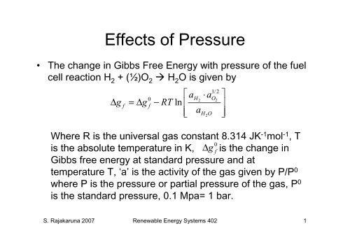
Effects of Pressure<br />
• The change in Gibbs Free Energy with pressure of the fuel<br />
cell reaction H 2 + (½)O 2 H 2 O is given by<br />
⎡ a ⋅ a ⎤<br />
1/2<br />
H O<br />
0<br />
2 2<br />
Δ g f = Δg f − RT ln ⎢ ⎥<br />
⎢⎣ aH2O<br />
⎥⎦<br />
Where R is the universal gas constant 8.314 JK-1mol-1 , T<br />
is the absolute temperature in K, is the change in<br />
Gibbs free energy at standard pressure and at<br />
temperature T, ‘a’ is the activity of the gas given by P/P0 where P is the pressure or partial pressure of the gas, P0 0<br />
Δg<br />
f<br />
is the standard pressure, 0.1 Mpa= 1 bar.<br />
S. Rajakaruna 2007 Renewable Energy Systems 402 1
Effects of Pressure<br />
• If the pressure of hydrogen and oxygen increase, Δg<br />
becomes more negative and hence releases more<br />
energy become available for conversion to electricity.<br />
• If the pressure of steam increases, less energy will be<br />
available for the conversion to electricity.<br />
• Note here that the effect of change of temperature is<br />
0<br />
represented by the change in the value of Δg<br />
with f<br />
changing temperature. The second term only represents<br />
the effect of pressure change.<br />
• The effect of temperature on maximum EMF can be<br />
−Δg<br />
f<br />
seen by substituting the above equation in<br />
E =<br />
S. Rajakaruna 2007 Renewable Energy Systems 402 2<br />
2F<br />
f
Change in EMF with Pressure -The<br />
Nernst Equation<br />
0<br />
1/2 1/2<br />
−Δg<br />
f RT ⎛ aH ⋅ a ⎞ O 0 RT ⎛ aH ⋅ a ⎞ O<br />
E = + ln = E + ln<br />
2F 2F a 2F<br />
a<br />
E<br />
0<br />
2 2 2 2<br />
⎜ ⎟ ⎜ ⎟<br />
⎜ ⎟ ⎜ ⎟<br />
⎝ H2O ⎠ ⎝ H2O ⎠<br />
Where is the maximum EMF at standard pressure<br />
0<br />
and temperature T (K). Note E<br />
drops with the<br />
increasing temperature as seen in Table 2.2. This is<br />
called ‘The Nernst Equation’ and some of its other forms<br />
are as given below.<br />
S. Rajakaruna 2007 Renewable Energy Systems 402 3
Nernst Equation<br />
E E<br />
0<br />
= +<br />
RT<br />
2F<br />
1<br />
⎛ ⎞<br />
2<br />
⎜ PH ⎛ P<br />
2 O ⎞ 2 ⋅⎜<br />
⎟<br />
⎜ 0 0 ⎟<br />
P P ⎟<br />
ln ⎜<br />
⎝ ⎠<br />
⎟<br />
P<br />
⎜ H2O ⎟<br />
⎜ 0 ⎟<br />
⎜ P ⎟<br />
⎝ ⎠<br />
If all the pressures are expressed in ‘bar’, then, P 0 =1. Hence above equation<br />
can be expressed as:<br />
E E<br />
RT<br />
⎛ ⎞<br />
⎜ PH ⋅ PO<br />
1<br />
2<br />
⎟<br />
( )<br />
0<br />
2 2<br />
= + ln ⎜ ⎟<br />
2F<br />
⎜<br />
PH<br />
2O<br />
⎟<br />
⎝ ⎠<br />
S. Rajakaruna 2007 Renewable Energy Systems 402 4
Nernst Equation<br />
• In nearly all the cases, pressures of gases in above<br />
equation are partial pressures as there are many gases<br />
in the mix both at anode and cathode.<br />
• Furthermore, the overall pressure in the mix of gases at<br />
the cathode and anode is the same. Because this<br />
simplifies the design of the cell. If this system operating<br />
pressure is ‘P’, then the partial pressures can be<br />
expressed as a ratio of P.<br />
P = α ⋅ P P = β ⋅ P P = δ ⋅ P<br />
H O H O<br />
2 2 2<br />
α, β and δ<br />
Where are constants depending on the<br />
concentration of gases in the mix.<br />
S. Rajakaruna 2007 Renewable Energy Systems 402 5
Nernst Equation<br />
1 1 1<br />
⎛ ⎞ ⎛ ⎞<br />
2 2 2<br />
0 RT α ⋅ β ⋅ P 0 RT α ⋅ β RT<br />
E = E + ln<br />
⎜ ⎟<br />
= E + ln<br />
⎜ ⎟<br />
+ ln P<br />
2F ⎜ δ ⎟ 2F ⎜ δ ⎟<br />
⎜ ⎟ ⎜ ⎟ 4F<br />
⎝ ⎠ ⎝ ⎠<br />
This form of Nernst equation gives the effect of system<br />
pressure P on the EMF as a separate term. It also shows<br />
how partial pressures influence the EMF.<br />
( )<br />
Example: On the cathode, oxygen is usually supplied as<br />
air. The partial pressures of air at 0.1MPa are: N 2 =0.0781<br />
MPa, O 2 =0.02095 MPa, Argon = 0.00093 MPa etc. Thus,<br />
β=0.2095 and P=0.1MPa= 1 bar<br />
The partial pressure of H 2 depends on how fuel processor<br />
produces hydrogen.<br />
S. Rajakaruna 2007 Renewable Energy Systems 402 6
<strong>Fuel</strong> and Oxygen Utilization<br />
• As hydrogen passes through the anode, it is used in the<br />
reaction. So the partial pressure of hydrogen will<br />
progressively decrease as it flows from one end to the<br />
other end of the anode.<br />
• The same is true for oxygen. As oxygen flows from one<br />
end to the other on the cathode, its partial pressure will<br />
also gradually decrease.<br />
• Since α and β both decrease, the EMF generated<br />
continues to drop as the gases flow from the entry (inlet)<br />
to the exit (outlet). It will be worst near the outlet.<br />
S. Rajakaruna 2007 Renewable Energy Systems 402 7
<strong>Fuel</strong> and Oxygen Utilization<br />
• Since the bipolar plates on the electrode are good<br />
conductors, there cannot be different voltages in the<br />
same cell. Therefore, it is the current density that drops<br />
as the gases flow towards outlet.<br />
⎛ ⎞<br />
1<br />
2<br />
0 RT α ⋅ β<br />
E = E + ln<br />
⎜ ⎟ RT<br />
+ ln P<br />
( )<br />
2F ⎜ δ ⎟<br />
⎜ ⎟ 4F<br />
⎝ ⎠<br />
• Due to the RT term, it is also clear that the effects of<br />
decreasing partial pressures is more at high<br />
temperature fuel cells such as ‘Solid Oxide <strong>Fuel</strong> Cell’.<br />
S. Rajakaruna 2007 Renewable Energy Systems 402 8
<strong>Fuel</strong> Utilization<br />
• For high fuel efficiency, it is required that all the fuel<br />
supplied to the cell used in the reaction. But at the same<br />
time it can be seen from the above discussion that the<br />
pressure of H 2 at outlet should not be reduced to very<br />
low levels. As a result, fuel and oxygen utilization need<br />
careful optimising, especially in high temperature fuel<br />
cells.<br />
• <strong>Fuel</strong> Utilization Ratio (u) is defined as,<br />
N N − N<br />
u = =<br />
N N<br />
used in out<br />
H H H<br />
2 2 2<br />
in in<br />
H H<br />
2 2<br />
S. Rajakaruna 2007 Renewable Energy Systems 402 9
<strong>Fuel</strong> Utilization Ratio<br />
where N is the flow rate in moles/s. For a solidoxide<br />
fuel cell the desired range of u is from 0.7<br />
to 0.9.<br />
• Overused-fuel condition: i.e. u> 0.9, will lead<br />
to fuel starvation near the outlet and cause<br />
permanent damage to cells.<br />
• Underused-fuel condition: i.e. u
Terminal Voltage of Practical <strong>Cells</strong><br />
−Δg<br />
• The maximum EMF given by the equation E =<br />
2F<br />
is an ideal value assuming there are no losses.<br />
The practical terminal voltage of a fuel cell is<br />
considerably less than the above value due to<br />
various types of losses.<br />
• At temperatures below 100°C, the maximum EMF<br />
E is about 1.2 V. Figure 3.1 shows the variation of<br />
terminal voltage with current density of a practical<br />
fuel cell operating at 40°C and standard pressure.<br />
S. Rajakaruna 2007 Renewable Energy Systems 402 11<br />
f
Terminal voltage of a low-<br />
temperature fuel cell<br />
S. Rajakaruna 2007 Renewable Energy Systems 402 12
Terminal voltage of a low-<br />
temperature fuel cell<br />
Note the following in the figure.<br />
• Even the open circuit voltage is less than the<br />
theoretical value.<br />
• There is a rapid initial fall in voltage with<br />
increasing current density.<br />
• Then there is a range of current density where<br />
drop of voltage is almost linear. In this linear<br />
region, the slope is less than in the initial region.<br />
• When current density approaches some high<br />
values, the voltage starts to fall rapidly.<br />
S. Rajakaruna 2007 Renewable Energy Systems 402 13
Terminal voltage of a high-<br />
temperature fuel cell<br />
• As discussed earlier, the maximum EMF (E) falls with<br />
the increasing temperature. At about 800°C, E is ab out<br />
1.0 V. Figure 3.2 shows how the terminal voltage of a<br />
practical cell at 800°C varies with the current den sity.<br />
Note the following in the figure.<br />
• Open circuit voltage is almost equal to the theoretical<br />
value.<br />
• There is no rapid drop in voltage at low current densities.<br />
The graph is much more linear.<br />
• At about the same high values of current densities, the<br />
voltage starts to fall rapidly.<br />
S. Rajakaruna 2007 Renewable Energy Systems 402 14
Terminal voltage of a high-<br />
temperature fuel cell<br />
S. Rajakaruna 2007 Renewable Energy Systems 402 15
<strong>Fuel</strong> Cell Irreversibilities – Causes<br />
of Voltage Drop<br />
• There are four main types of irreversibilities that cause<br />
the terminal voltage to drop below the Maximum EMF<br />
(E). E is also called the ‘ideal emf’, ‘no-loss emf’ or the<br />
‘reversible emf’.<br />
1. Activation Loss<br />
2. <strong>Fuel</strong> Crossover and Internal Currents<br />
3. Ohmic Losses<br />
4. Mass Transport or Concentration Loss<br />
S. Rajakaruna 2007 Renewable Energy Systems 402 16
Activation Loss<br />
• Activation Loss is the main reason for rapid drop in<br />
terminal voltage of low-temperature fuel cells at low<br />
current densities. It is caused by the slowness of the<br />
reactions taking place on the surface of the electrode. A<br />
portion of the available energy is lost in driving the<br />
chemical reaction or to supply the ‘activation energy’.<br />
• The activation loss of voltage is described by “Tafel<br />
Equation’ as:<br />
⎛ i ⎞<br />
Δ Va = Aln<br />
⎜ ⎟<br />
i<br />
⎝ 0 ⎠<br />
where A is a constant which is higher for slower<br />
reactions and i 0 is a constant higher for faster reactions.<br />
S. Rajakaruna 2007 Renewable Energy Systems 402 17
Activation Loss<br />
• For the slow<br />
reaction A is higher,<br />
i 0 is smaller.<br />
• For the fast<br />
reaction A is smaller<br />
and i 0 is higher.<br />
• Due to the<br />
logarithmic function<br />
it is i 0 which affects<br />
the voltage drop<br />
more.<br />
S. Rajakaruna 2007 Renewable Energy Systems 402 18
Activation Loss<br />
• The above equation describes the voltage drop only for i<br />
> i 0 . For i < i 0 , the voltage drop is zero. Therefore, higher<br />
the value of i 0 , the lower is the voltage drop.<br />
• The constant i 0 is called the ‘exchange current density’.<br />
This is the current corresponding to the electrode<br />
reaction in equilibrium under open-circuit condition.<br />
Under zero current supplied to the external circuit, the<br />
electrode reaction is still happening, but in both<br />
directions.<br />
At the cathode:<br />
At the anode: 2<br />
O + 4e + 4H ↔ 2H<br />
O<br />
− +<br />
2 2<br />
2H ↔ 4H +<br />
4e<br />
+ −<br />
S. Rajakaruna 2007 Renewable Energy Systems 402 19
Activation Loss<br />
• When the external circuit is switched on, the exchange<br />
current density is readily available so drawing a current<br />
up to i 0 will cause no voltage drop.<br />
• The anode and cathode have two different i 0 values as<br />
i 0a and i 0c respectively.<br />
• For a hydrogen fuel cell, i 0c
Effect of i 0<br />
S. Rajakaruna 2007 Renewable Energy Systems 402 21
Methods to increase i 0<br />
1. Increasing the cell temperature: Increase of<br />
temperature increases the reaction under open-circuit<br />
condition. Therefore i 0 is higher and the voltage drop is<br />
less. By considering low and high values for i 0, the<br />
shapes of V-I characteristics of Figure 3.1 and 3.2 at<br />
low current levels can be described. For a low<br />
temperature cell i 0 is about 0.1 mA and that for a<br />
800°C cell is about 10 mA, which is 100 times large r.<br />
2. Using more effective catalysts.<br />
3. Increasing the contact area of the electrode.<br />
4. Increasing reactant concentration. Ex. Use pure<br />
oxygen instead of air.<br />
5. Increasing the pressure of reactants.<br />
S. Rajakaruna 2007 Renewable Energy Systems 402 22
<strong>Fuel</strong> Crossover and Internal<br />
Currents<br />
• Although the electrolyte is not supposed to allow the<br />
passing of the fuel (H 2 ) and electrons between the two<br />
electrodes, a very small “leakage” does happen in all fuel<br />
cells. Both hydrogen and electron crossovers have the<br />
same effect that they reduce the charges available to the<br />
external circuit.<br />
• Although, this leakage current is not large enough to<br />
affect the energy efficiency, it does cause a very<br />
considerable drop in open-circuit voltage.<br />
• Because of the leakage, the current produced under<br />
open-circuit condition is not zero.<br />
• If i n is the internal current density, it can be considered<br />
in the Tafel equation as:<br />
S. Rajakaruna 2007 Renewable Energy Systems 402 23
<strong>Fuel</strong> Crossover and Internal<br />
Currents<br />
⎛ i + i ⎞ n<br />
V = E − Aln<br />
⎜ ⎟<br />
i<br />
⎝ 0 ⎠<br />
• Thus, the open-circuit terminal voltage is given by,<br />
ln n ⎛ i ⎞<br />
VOC = E − A ⎜ ⎟<br />
i<br />
⎝ 0 ⎠<br />
Using typical values for a low-temperature cell, E=<br />
1.2v, A=0.06 V, i 0 =0.04mA.cm -2 and i n =3 mA.cm-2, V-I<br />
characteristics can be drawn as below.<br />
S. Rajakaruna 2007 Renewable Energy Systems 402 24
Activation and Internal Current<br />
Losses<br />
Compare this with Figure 3.1 and see how closely it matches the V-I<br />
characteristic of a practical cell at low current densities.<br />
S. Rajakaruna 2007 Renewable Energy Systems 402 25
Ohmic Losses<br />
• Ohmic losses are due to the resistance to the flow of (a)<br />
electrons through the electrodes, bipolar plates and<br />
other stack connections and (b) ions through the<br />
electrolyte.<br />
• In most fuel cells, ohmic loss is mainly due to the<br />
electrolyte.<br />
• The voltage drop is directly proportional to the current<br />
density.<br />
Δ V = i ⋅r<br />
o<br />
Where i is the current density and r is the resistance<br />
per unit area.<br />
S. Rajakaruna 2007 Renewable Energy Systems 402 26
Ohmic Losses<br />
• Ohmic losses are important in all types of fuel<br />
cells. To reduce the ohmic losses, following<br />
can be done.<br />
1. Use of electrodes with highest possible<br />
conductivity.<br />
2. Good design and use of suitable material for<br />
bipolar plates.<br />
3. Making the electrolyte as thin as practically<br />
possible while making sure no direct contact<br />
between electrodes is possible and enough<br />
physical strength is available in the stack.<br />
S. Rajakaruna 2007 Renewable Energy Systems 402 27
Mass Transport or Concentration<br />
Loss<br />
• As current is drawn to the external circuit, gases are<br />
consumed, thus causing a reduction in pressure of both<br />
hydrogen and oxygen at the electrodes if the gas supply<br />
rates are constant. This reduction in pressure at<br />
electrodes due to consumption is the reason for the<br />
concentration loss.<br />
i<br />
• If is the limiting current corresponding to zero<br />
l<br />
pressure at the electrodes, the concentration loss can be<br />
expressed using the Nernst equation as,<br />
⎛ i ⎞<br />
Δ V = −B ln ⎜1− ⎟ for i ≤ i<br />
⎝ il<br />
⎠<br />
c l<br />
S. Rajakaruna 2007 Renewable Energy Systems 402 28
Concentration Loss<br />
⎛ i ⎞<br />
V = E + B ln ⎜1− ⎟<br />
⎝ il<br />
⎠<br />
E = 1.2 V , i =<br />
1000mA<br />
S. Rajakaruna 2007 Renewable Energy Systems 402 29<br />
l
Combined Effect of All Losses<br />
• The effects on terminal voltage by all the<br />
irreversibilities that were discussed can be<br />
represented by the following equation.<br />
⎛ i + i ⎞ ⎛ n i + i ⎞ n<br />
V = E − ( i + in ) r − Aln ⎜ ⎟ + B ln ⎜1− ⎟<br />
i i<br />
⎝ 0 ⎠ ⎝ l ⎠<br />
• Where E is the maximum EMF (reversible opencircuit<br />
voltage), V is the terminal voltage, i is the<br />
current density in the external circuit.<br />
S. Rajakaruna 2007 Renewable Energy Systems 402 30
Typical Values of Parameters<br />
S. Rajakaruna 2007 Renewable Energy Systems 402 31