tico 735 totaliser manual - Hengstler Encoders
tico 735 totaliser manual - Hengstler Encoders
tico 735 totaliser manual - Hengstler Encoders

You also want an ePaper? Increase the reach of your titles
YUMPU automatically turns print PDFs into web optimized ePapers that Google loves.
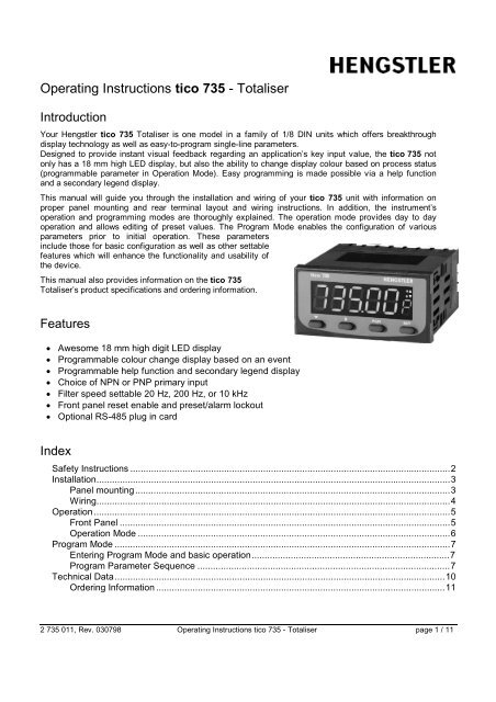
Operating Instructions <strong>tico</strong> <strong>735</strong> - Totaliser<br />
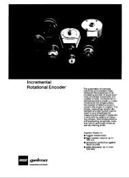
Introduction<br />
Your <strong>Hengstler</strong> <strong>tico</strong> <strong>735</strong> Totaliser is one model in a family of 1/8 DIN units which offers breakthrough<br />
display technology as well as easy-to-program single-line parameters.<br />
Designed to provide instant visual feedback regarding an application’s key input value, the <strong>tico</strong> <strong>735</strong> not<br />
only has a 18 mm high LED display, but also the ability to change display colour based on process status<br />
(programmable parameter in Operation Mode). Easy programming is made possible via a help function<br />
and a secondary legend display.<br />
This <strong>manual</strong> will guide you through the installation and wiring of your <strong>tico</strong> <strong>735</strong> unit with information on<br />
proper panel mounting and rear terminal layout and wiring instructions. In addition, the instrument’s<br />
operation and programming modes are thoroughly explained. The operation mode provides day to day<br />
operation and allows editing of preset values. The Program Mode enables the configuration of various<br />
parameters prior to initial operation. These parameters<br />
include those for basic configuration as well as other settable<br />
features which will enhance the functionality and usability of<br />
the device.<br />
This <strong>manual</strong> also provides information on the <strong>tico</strong> <strong>735</strong><br />
Totaliser’s product specifications and ordering information.<br />
Features<br />
• Awesome 18 mm high digit LED display<br />
• Programmable colour change display based on an event<br />
• Programmable help function and secondary legend display<br />
• Choice of NPN or PNP primary input<br />
• Filter speed settable 20 Hz, 200 Hz, or 10 kHz<br />
• Front panel reset enable and preset/alarm lockout<br />
• Optional RS-485 plug in card<br />
Index<br />
Safety Instructions ...........................................................................................................................2<br />
Installation........................................................................................................................................3<br />
Panel mounting.........................................................................................................................3<br />
Wiring........................................................................................................................................4<br />
Operation.........................................................................................................................................5<br />
Front Panel ...............................................................................................................................5<br />
Operation Mode ........................................................................................................................6<br />
Program Mode .................................................................................................................................7<br />
Entering Program Mode and basic operation............................................................................7<br />
Program Parameter Sequence .................................................................................................7<br />
Technical Data...............................................................................................................................10<br />
Ordering Information ...............................................................................................................11<br />
2 <strong>735</strong> 011, Rev. 030798 Operating Instructions <strong>tico</strong> <strong>735</strong> - Totaliser page 1 / 11
Safety Instructions<br />
This symbol indicates passages in the text which you have to pay special<br />
attention to so as to guarantee proper use and preclude any risk.<br />
• The range of applications for this product are industrial processes and controls, where the<br />
overvoltages applied to the product at the connection terminals are limited to values of the<br />
overvoltage category II.<br />
• This device is made and tested according to the valid standards of technics and has left the<br />
factory in a perfect safety state. To keep this state and secure operation without danger, the user<br />
has to observe the saftety and warning hints, contained in this operation <strong>manual</strong>.<br />
• Assembling and mounting of electrical divices are restricted to be done by skilled electricians!<br />
Skilled electrician is, who can judge the tasks deputed to him and foresee possible dangers, due<br />
to his special education, knowledge and experience and consciousness of the pertinent<br />
standards.<br />
• Mount devices are only allowed to be operated when mounted.<br />
• Finger protection at connection part of mount devices is to be secured when mounting!<br />
• While mounting the device, it must be secured that the requirements, which are asked for the<br />
device in the pertaining standards for safety, are not affected in a negative way, so reducing the<br />
safety of this mount device.<br />
• Mounting and assembling of device needs observation of the specifications of the local Energy<br />
Suppliers.<br />
• Before switching on, make sure that the power and control voltages are not exceeding the values<br />
in accordance with the technical data.<br />
• If it is to be assumed that operation without danger is not further possible, the device must be put<br />
out of operation and secured from unintentional operation! It must be assumed that an operation<br />
without danger is not further possible,<br />
if the device shows damage<br />
if the device stops functioning<br />
after a longer stocking period under unfavourable conditions<br />
after heavy strain during transportation.<br />
• If by a failure or a malfunction of the device, endangering of men or animals or damaging of<br />
facilities are possible, this must be avoided by additional safety measures (end switches,<br />
protection devices and etc.).<br />
• Before opening any cover, the device must be switched voltagefree.<br />
• <strong>Hengstler</strong> Counters are intended for industrial applications.<br />
• The mounting environment and nearby cabling have an important influence on the EMC (noise<br />
radiation and noise immunity) of the counter. When putting into operation, the EMC of the whole<br />
installation (unit) has to be secured. In particular, the relay outputs are to be protected from high<br />
noise radiation by suitable wiring.<br />
2 <strong>735</strong> 011, Rev. 030798 Operating Instructions <strong>tico</strong> <strong>735</strong> - Totaliser page 2 / 11
Installation<br />
Panel mounting<br />
The instrument can be mounted in a panel with a thickness of up to 12 mm. The cutout should be made based<br />
on the recommended panel opening illustrated in the drawing below.<br />
48<br />
<strong>tico</strong> <strong>735</strong><br />
45 + 0.5<br />
96<br />
92 + 0.5<br />
PGM RST<br />
Panel Cutout<br />
Insert the unit in the panel through the cutout. Ensure that the panel gasket is not distorted and the instrument is<br />
positioned squarely against the panel. Slide the mounting clamp into place on the instrument and push it<br />
forward until it is firmly in contact with the rear face of the mounting panel and the tabs on the bracket arm are<br />
seated in the mounting grooves on the side of the unit.<br />
The electronic components of the instrument can be removed from the housing after installation without<br />
disconnecting the wiring. To remove the components, grip the side edges of the panel and pull the instrument<br />
forward. Take note of orientation of the unit for subsequent replacement in the housing.<br />
2 <strong>735</strong> 011, Rev. 030798 Operating Instructions <strong>tico</strong> <strong>735</strong> - Totaliser page 3 / 11<br />
100
Wiring<br />
Rear Terminal<br />
Connections<br />
Count Inputs<br />
NC<br />
NC<br />
NC<br />
Power Supply<br />
(+)<br />
~<br />
(-)<br />
~<br />
NC<br />
B -<br />
RS 485<br />
A + 0V<br />
13 14 15 16 17 18 19 20 21<br />
12<br />
22<br />
11<br />
23<br />
10<br />
24<br />
9 8 7 6 5 4 3 2 1<br />
NC NC<br />
Terminal #2 is the connection for Input A, which is<br />
programmable to be the primary input or channel A of<br />
an encoder input. Terminal #1 is the connection for<br />
Input B, which is programmable to be an incrementing<br />
input, a decrementing input, or channel B of an<br />
encoder input. The common connection for both input<br />
A and input B is terminal #3.<br />
Control/Digital Inputs<br />
A contact closure or NPN signal can be used to<br />
activate preconfigured functionality. Terminal #5 is<br />
used for a remote reset function, while Terminal #6 is a<br />
security function, that when active, will prohibit entry<br />
into Program Mode. Terminal #8 serves as the<br />
common for both of these inputs.<br />
Auxiliary Power Output<br />
A 12 VDC for powering external sensors and encoders<br />
up to 125 mA can be accessed by connecting the<br />
positive supply side of the sensor to Terminal #4 and<br />
the negative side to Terminal #8.<br />
0 V<br />
CTRL 2<br />
CTRL 1<br />
Aux.<br />
Power<br />
2 <strong>735</strong> 011, Rev. 030798 Operating Instructions <strong>tico</strong> <strong>735</strong> - Totaliser page 4 / 11<br />
0 V<br />
NC NC NC<br />
Input A<br />
Input B<br />
NC<br />
NC<br />
NC<br />
Danger! Hazardeous<br />
voltage!<br />
Power Supply Input<br />
For an AC powered unit, Terminal #13 serves as the line<br />
or hot side connection for AC powered units and as the<br />
positive side for DC powered units. The neutral side for<br />
AC powered units and the negative side for DC powered<br />
units are connected to terminal #14.<br />
Serial Communication<br />
An RS-485 communication board, utilizing ASCII<br />
protocol, can be installed as an option. Terminals #16<br />
and #17 serve as the B and A connections respectively,<br />
while terminal #18 is connected as the common.<br />
Terminals 7, 9, 10, 11, 12, 15, 19, 20, 21, 22,<br />
23 & 24 are not used and must not be<br />
connected.
Operation<br />
Front Panel<br />
Down Scroll Program Reset<br />
Key functions<br />
Key Function<br />
Down In Operation Mode: Used in Edit Operation<br />
to decrement the digit highlighted by the<br />
Scroll Key<br />
In Program Mode: Used in Edit Operation<br />
to decrement the digit highlighted by the<br />
Scroll Key, if the setting is a numerical<br />
value, or present the next in the series of<br />
choices for that parameter<br />
Scroll InAll Modes: Moves the unit into Edit<br />
Operation, which is indicated by the left<br />
most digit flashing. Successive presses of<br />
the key are used to move to the digit to be<br />
edited. Wrap around will occur from least<br />
significant digit to most significant digit.<br />
Program InOperation Mode: Used to move between<br />
the count value display & the preset and to<br />
enter an edited preset value. Holding the<br />
key down for 3 seconds will cause the unit<br />
to enter Program Mode.<br />
In Program Mode: Used to move from one<br />
parameter to the next and enter the edited<br />
parameter values. Holding the key down for<br />
3 seconds will cause the unit to return to<br />
Operation Mode.<br />
Reset In Operation Mode: Resets the count value<br />
to zero (or to the preset in count down<br />
operation). This button can be disabled via<br />
the „Front Panel Reset Enable“ parameter<br />
in Program Mode.<br />
In Program Mode: No function<br />
Down & In All Modes: Will abort an Edit Operation<br />
Scroll and return the preset/parameter to its<br />
previous value.<br />
<br />
Output<br />
Indicators<br />
Primary<br />
Display<br />
Secondary<br />
Display<br />
Display functions<br />
Display Function<br />
Primary In Operation Mode: Default display is the<br />
count value. Can be scrolled using the<br />
program key to display the Preset value.<br />
If the „Help“ function is enabled, this<br />
display will first show the parameter<br />
description for 3 seconds ( see page 5 for<br />
example).<br />
In Control Mode: Displays the value or<br />
selection for the current parameter. If the<br />
„Help“ function is enabled, this display will<br />
first show the parameter description for 3<br />
seconds ( see page 6 for example).<br />
Secondary In Operation Mode: Indicates<br />
alphabetically if the Preset is being<br />
viewed on the primary display. This<br />
display is blank when the Count Value is<br />
being shown.<br />
In Program Mode: Provides a 1 digit<br />
alpha or numeric character to indicate<br />
which parameter value is being shown on<br />
the primary display.<br />
Output No function<br />
indicators<br />
No function<br />
2 <strong>735</strong> 011, Rev. 030798 Operating Instructions <strong>tico</strong> <strong>735</strong> - Totaliser page 5 / 11
Operation Mode<br />
Changing a Preset value (example)<br />
<br />
<br />
<br />
<br />
Display Parameter Sequence<br />
<br />
Default display is the present<br />
count value.<br />
Pressing the Program Key will<br />
cause the display description to<br />
appear on the main display.* If<br />
there is no key activity for 3<br />
seconds, the primary display will<br />
switch back to the count value.<br />
Continued pressing of the<br />
Program Key will scroll to the<br />
Preset. (see parameter sequence<br />
below.) The full parameter<br />
description will appear on the<br />
main display.*<br />
To change the Preset value,<br />
press the Scroll Key. If there was<br />
no key activity for 3 seconds, the<br />
Preset value will appear (one<br />
digit description shown on<br />
secondary display); however,<br />
press the Scroll Key in order to<br />
edit. The unit will now be in Edit<br />
Operation as signified by the<br />
most significant digit flashing.**<br />
Count<br />
Function: Displays the present<br />
count value.<br />
Adjustment Range: 0 to 99999<br />
<br />
<br />
<br />
Use the Scroll Key to move from<br />
left to right and highlight the digit<br />
that needs to be changed. Wrap<br />
around will occur from the least<br />
significant to the most significant<br />
digit.<br />
Use the Down Key to decrement<br />
the digit until the desired value<br />
appears. The display will wrap<br />
around from 0 to 9.<br />
After the desired digits have been<br />
changed, press the Program Key<br />
to enter the new value. The new<br />
value will appear on the main<br />
display without any flashing<br />
digits. Press the Program Key<br />
again and the parameter<br />
description will appear on the<br />
main display.<br />
* Parameter descriptions will not appear on the<br />
primary display if the „Help“ function has been<br />
disabled<br />
** Edit Operation cannot be accessed if the Preset<br />
Lock has been enabled in Program Mode<br />
<br />
<br />
Preset<br />
Function: Sets preset value - only<br />
used to change the display colour.<br />
Adjustment Range: 0 to 99999<br />
Default Value: 10<br />
2 <strong>735</strong> 011, Rev. 030798 Operating Instructions <strong>tico</strong> <strong>735</strong> - Totaliser page 6 / 11
Program Mode<br />
Entering Program Mode and basic operation<br />
The Program Mode can be<br />
accessed from the Operation<br />
Mode by holding the Program<br />
Key for 3 seconds.<br />
The name of the first parameter<br />
will appear on the primary<br />
display.*<br />
Successive presses of the<br />
Program Key will scroll the<br />
display through the remaining<br />
parameters in the Program<br />
Mode. To exit Program Mode,<br />
hold the Program Key for 3<br />
seconds.<br />
* Parameter names will not<br />
appear on the main display if<br />
the „Help“ function has been<br />
disabled in Program Mode<br />
<br />
⇑ ⇓<br />
for 3 secs.<br />
<br />
<br />
Program Parameter Sequence<br />
<br />
<br />
<br />
<br />
<br />
<br />
The Program Mode can be exited by holding the Program<br />
Key for 3 seconds or remove power from the unit and<br />
repower it.<br />
After 90 seconds of key inactivity the unit returns to<br />
Operation Mode automatically.<br />
3 secs. or<br />
⇐<br />
2 <strong>735</strong> 011, Rev. 030798 Operating Instructions <strong>tico</strong> <strong>735</strong> - Totaliser page 7 / 11<br />
⇒<br />
Edit Operation<br />
<br />
<br />
Pressing the Scroll Key or no key activity<br />
for 3 seconds will display the value for that<br />
parameter. The secondary display will<br />
indicate the one-digit identifier for the<br />
parameter. The digit in the secondary<br />
display will flash to indicate the unit is in<br />
Program Mode. If the Scroll Key was<br />
pressed (instead of waiting 3 seconds), the<br />
unit is in Edit Operation, as indicated by the<br />
MSD flashing. If there had been no key<br />
activity for 3 seconds, press the scroll key<br />
to enter Edit Operation (MSD flashing). Use<br />
the scroll and edit keys to change the value<br />
as in Operation Mode, described on page 5.<br />
Press the Program Key to enter any<br />
changes.<br />
Calibration Factor<br />
Function: Scales the input into engeneering units by multiplying this value by the number of pulses<br />
received.<br />
Adjustment Range: 0.0001 to 9.9999<br />
Default Value: 1.0000<br />
Decimal Position<br />
Function: Set the decimal point position for the count and preset displays. The setting of the<br />
decimal point merely switches the display dot and has no influence on the calibration calculation.<br />
Adjustment Range: 0 (no dp) to 0.0000<br />
Default Value: 0 (no dp)<br />
Count Mode<br />
Function: Defines how the input pulses will be applied to the count value. Note: the sum of both<br />
input frequencies should not exceed 10 kHz.<br />
Adjustment Range:<br />
<br />
<br />
A+B: Inputs on both<br />
the A & B channels<br />
increment the total<br />
Default Value: A+B<br />
<br />
<br />
A-B: Inputs on the A<br />
channel increment the<br />
total, while inputs on the<br />
B channel decrement<br />
<br />
<br />
Directional: When<br />
input B is inactive,<br />
input A increments.<br />
When input B is<br />
active, input A<br />
decrements.<br />
<br />
<br />
Quadrature: The unit<br />
accepts a phased input<br />
from an encoder. The<br />
total increments when<br />
the A channel leads the<br />
B channel.
Input Type<br />
Function: Programs the unit to match the electrical characteristics of the input signal<br />
Adjustment Range:<br />
<br />
<br />
Sinking: The unit will<br />
accept an NPN or dry<br />
contact which sinks<br />
voltage to common<br />
<br />
2 <strong>735</strong> 011, Rev. 030798 Operating Instructions <strong>tico</strong> <strong>735</strong> - Totaliser page 8 / 11<br />
<br />
Source: The unit will<br />
accept an PNP input<br />
which sources voltage<br />
Default Value:<br />
Source<br />
Filter Speed<br />
Function: Enables the debounce filter of the counter to properly match the application<br />
Adjustment Range:<br />
<br />
<br />
20: The unit will accept<br />
up to 20 pulses per<br />
second. Generally<br />
used with contact<br />
inputs to eliminate<br />
false counts caused by<br />
contact bounce<br />
<br />
<br />
200: The unit will accept<br />
up to 200 pulses per<br />
second. Generally used<br />
for higher speed contact<br />
inputs or to filter noise<br />
on electronic signals in<br />
low speed applications<br />
<br />
<br />
10,000: The unit will<br />
accept up to 10,000<br />
pulses per second.<br />
Generally used with<br />
high speed electronic<br />
inputs and encoders<br />
Default Value: 10000<br />
Front Panel Reset Enable<br />
Function: Determines whether the Front Panel Reset key can be used to reset the count<br />
value.<br />
Adjustment Range:<br />
<br />
<br />
Enable: The count<br />
value can be reset<br />
while being viewed in<br />
Operation Mode by<br />
pressing the Front<br />
Panel Reset Key<br />
<br />
<br />
Disabled: The Front<br />
Panel Reset Key is<br />
disabled and the count<br />
value can only be reset<br />
through the Remote<br />
Reset Input<br />
Default Value: Enable<br />
Serial Communication enabled (Appears only if communication board is installed and<br />
activated)<br />
Function: Activates the RS-485 communication option board.<br />
Adjustment Range:<br />
<br />
<br />
None: no communication<br />
board installed<br />
<br />
<br />
Fitted: A communication<br />
board is installed in<br />
the unit<br />
Communication Address<br />
(Appears only if communication board is installed and activated)<br />
Function: Defines the unique communication address of the counter<br />
Adjustment Range: 1 to 99<br />
Default Value: 1<br />
Default Value: If ordered from the factory<br />
with the RS-485 board, the default will be<br />
„Fitted“. If the board is installed in the field,<br />
this parameter will need to be changed<br />
fromt its default of „none“.
Baud Rate<br />
(Appears only if communication board is installed and activated)<br />
Function: Selects the serial communication speed<br />
Adjustment Range:<br />
<br />
1200 BPS<br />
<br />
<br />
2400 BPS<br />
2 <strong>735</strong> 011, Rev. 030798 Operating Instructions <strong>tico</strong> <strong>735</strong> - Totaliser page 9 / 11<br />
<br />
<br />
<br />
Default: 4800 BPS<br />
<br />
9600 BPS<br />
Display Colour Change<br />
Function: Defines the colour of the display for prior to and after the preset value is reached<br />
Adjustment Range:<br />
<br />
<br />
Red: The display will<br />
always be red<br />
Default Value:<br />
Green to red<br />
<br />
<br />
Green: The display<br />
will always be green<br />
<br />
<br />
Green to Red: The<br />
display will be green<br />
prior to the preset value<br />
being reached. It will<br />
turn red after the preset<br />
has been reached<br />
<br />
<br />
<br />
Red to Green: The<br />
display will be red prior<br />
to the preset value<br />
being reached. It will<br />
turn green after the<br />
preset has been<br />
reached<br />
Preset Lock<br />
Function: Determins whether the Preset Value changes via the front panel are locked out.<br />
Adjustment Range:<br />
<br />
<br />
Locking Enable. Preset<br />
value can be viewed<br />
and changed<br />
<br />
<br />
Locking Disabled.<br />
Preset value is read<br />
only<br />
Default Value: Disable<br />
Help Prompt<br />
Function: Determines whether the multi-character parameter name will appear on the main display<br />
for 3 seconds prior to the paramter value appearing.<br />
Adjustment Range:<br />
<br />
<br />
Help-Yes: Multi<br />
character parameter<br />
descriptions will<br />
appear on the primary<br />
display. The value<br />
associated with that<br />
parameter will appear<br />
by pressing the scroll<br />
key or waiting for 3<br />
seconds<br />
<br />
<br />
Help-No: Only the<br />
parameter values will<br />
appear on the primary<br />
display. The parameter<br />
can be identified by a<br />
single digit in the<br />
secondary display<br />
Default Value:<br />
Help Yes
Technical Data<br />
<br />
<br />
<br />
<br />
<br />
<br />
<br />
<br />
<br />
<br />
<br />
<br />
<br />
<br />
<br />
<br />
<br />
<br />
<br />
<br />
<br />
≥ <br />
<br />
≥ <br />
<br />
<br />
<br />
<br />
<br />
≥ <br />
<br />
≥ <br />
<br />
<br />
<br />
<br />
2 <strong>735</strong> 011, Rev. 030798 Operating Instructions <strong>tico</strong> <strong>735</strong> - Totaliser page 10 / 11
Ordering Information<br />
Relay 2<br />
0 none Communications<br />
1 with Relay 2 0 none<br />
(only with function 4,5,8,9) 5 with RS 485<br />
0 <strong>735</strong> P<br />
Function Power Supply<br />
1 Totaliser 0 90...264V AC<br />
2 Position Indicator 2 20...50V~ or<br />
4 Tacho/Rate Meter 22...55V=<br />
5 Rate & Totaliser<br />
6 Time Counter Linear Output<br />
7 1 Preset Counter 0 none<br />
8 2 Preset Counter 3 with 4-20 mA<br />
9 Batch Counter (only with function 2,4,5)<br />
<br />
<br />
<br />
<br />
<br />
<br />
<br />
<br />
<br />
<br />
2 <strong>735</strong> 011, Rev. 030798 Operating Instructions <strong>tico</strong> <strong>735</strong> - Totaliser page 11 / 11