Programming manual M238 | 3 MB - BERGER - POSITEC
Programming manual M238 | 3 MB - BERGER - POSITEC
Programming manual M238 | 3 MB - BERGER - POSITEC

Create successful ePaper yourself
Turn your PDF publications into a flip-book with our unique Google optimized e-Paper software.
EIO0000000384.04<br />
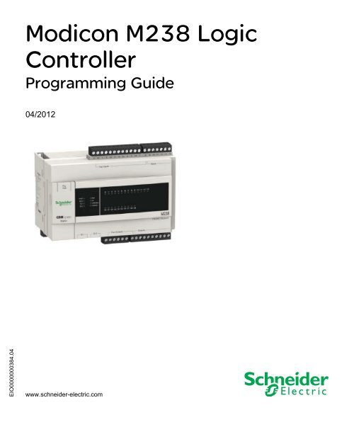
Modicon <strong>M238</strong> Logic Controller<br />
EIO0000000384 04/2012<br />
Modicon <strong>M238</strong> Logic<br />
Controller<br />
<strong>Programming</strong> Guide<br />
04/2012<br />
www.schneider-electric.com
The information provided in this documentation contains general descriptions and/or<br />
technical characteristics of the performance of the products contained herein. This<br />
documentation is not intended as a substitute for and is not to be used for<br />
determining suitability or reliability of these products for specific user applications. It<br />
is the duty of any such user or integrator to perform the appropriate and complete<br />
risk analysis, evaluation and testing of the products with respect to the relevant<br />
specific application or use thereof. Neither Schneider Electric nor any of its affiliates<br />
or subsidiaries shall be responsible or liable for misuse of the information contained<br />
herein. If you have any suggestions for improvements or amendments or have found<br />
errors in this publication, please notify us.<br />
No part of this document may be reproduced in any form or by any means, electronic<br />
or mechanical, including photocopying, without express written permission of<br />
Schneider Electric.<br />
All pertinent state, regional, and local safety regulations must be observed when<br />
installing and using this product. For reasons of safety and to help ensure<br />
compliance with documented system data, only the manufacturer should perform<br />
repairs to components.<br />
When devices are used for applications with technical safety requirements, the<br />
relevant instructions must be followed.<br />
Failure to use Schneider Electric software or approved software with our hardware<br />
products may result in injury, harm, or improper operating results.<br />
Failure to observe this information can result in injury or equipment damage.<br />
© 2012 Schneider Electric. All rights reserved.<br />
2 EIO0000000384 04/2012
Table of Contents<br />
Safety Information . . . . . . . . . . . . . . . . . . . . . . . . . . . . . . 7<br />
About the Book . . . . . . . . . . . . . . . . . . . . . . . . . . . . . . . . . 9<br />
Chapter 1 About the Modicon <strong>M238</strong> Logic Controller . . . . . . . . . . 13<br />
Modicon <strong>M238</strong> Logic Controller Devices Overview. . . . . . . . . . . . . . . . . . 13<br />
Chapter 2 How to Configure the Controller . . . . . . . . . . . . . . . . . . . 15<br />
How to Configure the Controller . . . . . . . . . . . . . . . . . . . . . . . . . . . . . . . . 15<br />
Chapter 3 Libraries. . . . . . . . . . . . . . . . . . . . . . . . . . . . . . . . . . . . . . . 19<br />
Libraries. . . . . . . . . . . . . . . . . . . . . . . . . . . . . . . . . . . . . . . . . . . . . . . . . . . 19<br />
Chapter 4 Supported Standard Data Types . . . . . . . . . . . . . . . . . . . 21<br />
Supported Standard Data Types. . . . . . . . . . . . . . . . . . . . . . . . . . . . . . . . 21<br />
Chapter 5 Memory Mapping . . . . . . . . . . . . . . . . . . . . . . . . . . . . . . . 23<br />
Memory Organization . . . . . . . . . . . . . . . . . . . . . . . . . . . . . . . . . . . . . . . . 24<br />
Relocation Table . . . . . . . . . . . . . . . . . . . . . . . . . . . . . . . . . . . . . . . . . . . . 28<br />
Chapter 6 Tasks . . . . . . . . . . . . . . . . . . . . . . . . . . . . . . . . . . . . . . . . . 31<br />
Maximum Number of Tasks . . . . . . . . . . . . . . . . . . . . . . . . . . . . . . . . . . . 32<br />
Task Configuration Screen . . . . . . . . . . . . . . . . . . . . . . . . . . . . . . . . . . . . 33<br />
Task Types . . . . . . . . . . . . . . . . . . . . . . . . . . . . . . . . . . . . . . . . . . . . . . . . 35<br />
System and Task Watchdogs . . . . . . . . . . . . . . . . . . . . . . . . . . . . . . . . . . 38<br />
Task Priorities . . . . . . . . . . . . . . . . . . . . . . . . . . . . . . . . . . . . . . . . . . . . . . 39<br />
Default Task Configuration . . . . . . . . . . . . . . . . . . . . . . . . . . . . . . . . . . . . 41<br />
Chapter 7 Controller States and Behaviors . . . . . . . . . . . . . . . . . . . 43<br />
7.1 Controller State Diagram. . . . . . . . . . . . . . . . . . . . . . . . . . . . . . . . . . . . . . 44<br />
Controller State Diagram. . . . . . . . . . . . . . . . . . . . . . . . . . . . . . . . . . . . . . 44<br />
7.2 Controller States Description. . . . . . . . . . . . . . . . . . . . . . . . . . . . . . . . . . . 49<br />
Controller States Description. . . . . . . . . . . . . . . . . . . . . . . . . . . . . . . . . . . 49<br />
7.3 State Transitions and System Events . . . . . . . . . . . . . . . . . . . . . . . . . . . . 53<br />
Controller States and Output Behavior . . . . . . . . . . . . . . . . . . . . . . . . . . . 54<br />
Commanding State Transitions. . . . . . . . . . . . . . . . . . . . . . . . . . . . . . . . . 57<br />
Error Detection, Types, and Management . . . . . . . . . . . . . . . . . . . . . . . . 63<br />
Remanent Variables . . . . . . . . . . . . . . . . . . . . . . . . . . . . . . . . . . . . . . . . . 64<br />
EIO0000000384 04/2012 3
Chapter 8 Controller Device Editor . . . . . . . . . . . . . . . . . . . . . . . . . . 65<br />
Controller Parameters . . . . . . . . . . . . . . . . . . . . . . . . . . . . . . . . . . . . . . . 66<br />
Applications . . . . . . . . . . . . . . . . . . . . . . . . . . . . . . . . . . . . . . . . . . . . . . . 68<br />
PLC Settings . . . . . . . . . . . . . . . . . . . . . . . . . . . . . . . . . . . . . . . . . . . . . . 69<br />
Services . . . . . . . . . . . . . . . . . . . . . . . . . . . . . . . . . . . . . . . . . . . . . . . . . . 71<br />
Chapter 9 <strong>M238</strong> Embedded Functions . . . . . . . . . . . . . . . . . . . . . . . 73<br />
HSC Embedded Function . . . . . . . . . . . . . . . . . . . . . . . . . . . . . . . . . . . . 74<br />
I/O Embedded Function. . . . . . . . . . . . . . . . . . . . . . . . . . . . . . . . . . . . . . 76<br />
PTO_PWM Embedded Function . . . . . . . . . . . . . . . . . . . . . . . . . . . . . . . 80<br />
Chapter 10 Expansion Modules Configuration. . . . . . . . . . . . . . . . . . 83<br />
General Description . . . . . . . . . . . . . . . . . . . . . . . . . . . . . . . . . . . . . . . . . 83<br />
Chapter 11 CANopen Configuration . . . . . . . . . . . . . . . . . . . . . . . . . . 85<br />
CANopen Interface Configuration . . . . . . . . . . . . . . . . . . . . . . . . . . . . . . 85<br />
Chapter 12 AS-Interface Configuration . . . . . . . . . . . . . . . . . . . . . . . . 89<br />
Presentation of the AS-Interface V2 Fieldbus . . . . . . . . . . . . . . . . . . . . . 90<br />
General Functional Description . . . . . . . . . . . . . . . . . . . . . . . . . . . . . . . . 91<br />
Software Setup Principles . . . . . . . . . . . . . . . . . . . . . . . . . . . . . . . . . . . . 94<br />
Add an AS-Interface Master Module . . . . . . . . . . . . . . . . . . . . . . . . . . . . 95<br />
Configure an AS-Interface Master . . . . . . . . . . . . . . . . . . . . . . . . . . . . . . 97<br />
Add an AS-Interface Slave. . . . . . . . . . . . . . . . . . . . . . . . . . . . . . . . . . . . 100<br />
Configure an AS-Interface Slave . . . . . . . . . . . . . . . . . . . . . . . . . . . . . . . 109<br />
Automatic Addressing of an AS-Interface V2 Slave. . . . . . . . . . . . . . . . . 112<br />
Modification of Slave Address . . . . . . . . . . . . . . . . . . . . . . . . . . . . . . . . . 113<br />
System Diagnostic in Online Mode . . . . . . . . . . . . . . . . . . . . . . . . . . . . . 116<br />
<strong>Programming</strong> for the AS-Interface V2 Fieldbus . . . . . . . . . . . . . . . . . . . . 120<br />
Configuration of a Replaced AS-Interface V2 Slave . . . . . . . . . . . . . . . . 121<br />
Chapter 13 Serial Line Configuration . . . . . . . . . . . . . . . . . . . . . . . . . 123<br />
Serial Lines Configuration . . . . . . . . . . . . . . . . . . . . . . . . . . . . . . . . . . . . 124<br />
ASCII Manager . . . . . . . . . . . . . . . . . . . . . . . . . . . . . . . . . . . . . . . . . . . . 128<br />
SoMachine Network Manager . . . . . . . . . . . . . . . . . . . . . . . . . . . . . . . . . 131<br />
Modbus IOScanner . . . . . . . . . . . . . . . . . . . . . . . . . . . . . . . . . . . . . . . . . 133<br />
Modbus Manager. . . . . . . . . . . . . . . . . . . . . . . . . . . . . . . . . . . . . . . . . . . 143<br />
Adding a Modem to a Manager . . . . . . . . . . . . . . . . . . . . . . . . . . . . . . . . 148<br />
Chapter 14 499TWD01100 Ethernet/Modbus Gateway. . . . . . . . . . . . 149<br />
Connection and Configuration of the Ethernet Gateway . . . . . . . . . . . . . 149<br />
Chapter 15 Connecting the Modicon <strong>M238</strong> Logic Controller to a PC 155<br />
Connecting the Controller to a PC . . . . . . . . . . . . . . . . . . . . . . . . . . . . . . 156<br />
Active Path of the Controller . . . . . . . . . . . . . . . . . . . . . . . . . . . . . . . . . . 159<br />
4 EIO0000000384 04/2012
Chapter 16 Loader Device Accessory . . . . . . . . . . . . . . . . . . . . . . . . 161<br />
16.1 About the Loader Device Accessory . . . . . . . . . . . . . . . . . . . . . . . . . . . . . 162<br />
Loader Device AccessoryDescription . . . . . . . . . . . . . . . . . . . . . . . . . . . . 163<br />
Physical Description . . . . . . . . . . . . . . . . . . . . . . . . . . . . . . . . . . . . . . . . . 165<br />
LED Status and Diagnostic . . . . . . . . . . . . . . . . . . . . . . . . . . . . . . . . . . . . 167<br />
Firmware and SoMachine Software Compatibility. . . . . . . . . . . . . . . . . . . 169<br />
16.2 Upload From SoMachine to the USB Memory Key. . . . . . . . . . . . . . . . . . 171<br />
Transfer From SoMachine to the USB Memory Key. . . . . . . . . . . . . . . . . 171<br />
16.3 File Transfer with a USB Memory Key . . . . . . . . . . . . . . . . . . . . . . . . . . . 172<br />
Upload From the Controller to the USB Memory Key . . . . . . . . . . . . . . . . 173<br />
Download From the USB Memory Key to the Controller . . . . . . . . . . . . . 174<br />
16.4 Other Functionalities . . . . . . . . . . . . . . . . . . . . . . . . . . . . . . . . . . . . . . . . . 177<br />
Set the Controller to RUNNING State . . . . . . . . . . . . . . . . . . . . . . . . . . . . 178<br />
Update the Firmware of the Loader Device Accessory. . . . . . . . . . . . . . . 179<br />
Chapter 17 Updating the Controller Firmware . . . . . . . . . . . . . . . . . 181<br />
Updating Through Serial Line . . . . . . . . . . . . . . . . . . . . . . . . . . . . . . . . . . 182<br />
Updating Through USB . . . . . . . . . . . . . . . . . . . . . . . . . . . . . . . . . . . . . . . 185<br />
Launching the Exec Loader Wizard . . . . . . . . . . . . . . . . . . . . . . . . . . . . . 187<br />
Step 1 - Welcome . . . . . . . . . . . . . . . . . . . . . . . . . . . . . . . . . . . . . . . . . . . 188<br />
Step 2 - Settings . . . . . . . . . . . . . . . . . . . . . . . . . . . . . . . . . . . . . . . . . . . . 189<br />
Step 3 - File and Device Exec Properties . . . . . . . . . . . . . . . . . . . . . . . . . 191<br />
Step 4 - Transfer Progress . . . . . . . . . . . . . . . . . . . . . . . . . . . . . . . . . . . . 193<br />
Chapter 18 Modicon <strong>M238</strong> Logic Controller - Troubleshooting and<br />
FAQ . . . . . . . . . . . . . . . . . . . . . . . . . . . . . . . . . . . . . . . . . . 195<br />
Troubleshooting. . . . . . . . . . . . . . . . . . . . . . . . . . . . . . . . . . . . . . . . . . . . . 196<br />
Frequently Asked Questions . . . . . . . . . . . . . . . . . . . . . . . . . . . . . . . . . . . 203<br />
Appendices . . . . . . . . . . . . . . . . . . . . . . . . . . . . . . . . . . . . . . . . . . . 205<br />
Appendix A AS-Interface Library . . . . . . . . . . . . . . . . . . . . . . . . . . . . . 207<br />
ASI_CheckSlaveBit . . . . . . . . . . . . . . . . . . . . . . . . . . . . . . . . . . . . . . . . . . 208<br />
ASI_CmdSetAutoAddressing . . . . . . . . . . . . . . . . . . . . . . . . . . . . . . . . . . 209<br />
ASI_CmdSetDataExchange . . . . . . . . . . . . . . . . . . . . . . . . . . . . . . . . . . . 211<br />
ASI_CmdSetOfflineMode . . . . . . . . . . . . . . . . . . . . . . . . . . . . . . . . . . . . . 213<br />
ASI_MasterStatusCheck . . . . . . . . . . . . . . . . . . . . . . . . . . . . . . . . . . . . . . 215<br />
ASI_SlaveAddressChange . . . . . . . . . . . . . . . . . . . . . . . . . . . . . . . . . . . . 217<br />
ASI_SlaveParameterUpdate . . . . . . . . . . . . . . . . . . . . . . . . . . . . . . . . . . . 220<br />
ASI_SlaveStatusCheck . . . . . . . . . . . . . . . . . . . . . . . . . . . . . . . . . . . . . . . 222<br />
ASI_ReadParameterImage . . . . . . . . . . . . . . . . . . . . . . . . . . . . . . . . . . . . 224<br />
Appendix B Function and Function Block Representation . . . . . . . 227<br />
Differences Between a Function and a Function Block. . . . . . . . . . . . . . . 228<br />
How to Use a Function or a Function Block in IL Language . . . . . . . . . . . 229<br />
How to Use a Function or a Function Block in ST Language . . . . . . . . . . 232<br />
EIO0000000384 04/2012 5
Appendix C Functions to Get/Set Serial Line Configuration in User<br />
Program . . . . . . . . . . . . . . . . . . . . . . . . . . . . . . . . . . . . . . . 235<br />
GetSerialConf: Get the Serial Line Configuration . . . . . . . . . . . . . . . . . . 236<br />
SetSerialConf: Change the Serial Line Configuration . . . . . . . . . . . . . . . 237<br />
SERIAL_CONF: Structure of the Serial Line Configuration Data Type . . 239<br />
Appendix D Controller Performance . . . . . . . . . . . . . . . . . . . . . . . . . . 241<br />
Processing Performance . . . . . . . . . . . . . . . . . . . . . . . . . . . . . . . . . . . . . 241<br />
Glossary . . . . . . . . . . . . . . . . . . . . . . . . . . . . . . . . . . . . . . . . . . . 243<br />
Index . . . . . . . . . . . . . . . . . . . . . . . . . . . . . . . . . . . . . . . . . . . 255<br />
6 EIO0000000384 04/2012
Important Information<br />
NOTICE<br />
Safety Information<br />
Read these instructions carefully, and look at the equipment to become familiar with<br />
the device before trying to install, operate, or maintain it. The following special<br />
messages may appear throughout this documentation or on the equipment to warn<br />
of potential hazards or to call attention to information that clarifies or simplifies a<br />
procedure.<br />
EIO0000000384 04/2012 7<br />
§
PLEASE NOTE<br />
Electrical equipment should be installed, operated, serviced, and maintained only by<br />
qualified personnel. No responsibility is assumed by Schneider Electric for any<br />
consequences arising out of the use of this material.<br />
A qualified person is one who has skills and knowledge related to the construction<br />
and operation of electrical equipment and its installation, and has received safety<br />
training to recognize and avoid the hazards involved.<br />
8 EIO0000000384 04/2012
At a Glance<br />
Document Scope<br />
Validity Note<br />
Related Documents<br />
About the Book<br />
The purpose of this document is to help you to configure your Modicon <strong>M238</strong> Logic<br />
Controller.<br />
NOTE: Read and understand this document and all related documents (see page 9)<br />
before installing, operating, or maintaining your Modicon <strong>M238</strong> Logic Controller.<br />
Modicon <strong>M238</strong> Logic Controller users should read through the entire document to<br />
understand all of its features.<br />
This document has been updated with the release of SoMachine V3.1.<br />
Title of Documentation Reference Number<br />
SoMachine <strong>Programming</strong> Guide EIO0000000067 (ENG);<br />
EIO0000000069 (FRE);<br />
EIO0000000068 (GER);<br />
EIO0000000071 (SPA);<br />
EIO0000000070 (ITA);<br />
EIO0000000072 (CHS)<br />
Modicon <strong>M238</strong> Logic Controller Hardware Guide EIO0000000016 (ENG);<br />
EIO0000000017 (FRE);<br />
EIO0000000018 (GER);<br />
EIO0000000019 (SPA);<br />
EIO0000000020 (ITA);<br />
EIO0000000021 (CHS)<br />
EIO0000000384 04/2012 9
Modicon TM2 Expansion Modules Configuration <strong>Programming</strong><br />
Guide<br />
Modicon <strong>M238</strong> Logic Controller System Functions and Variables<br />
<strong>M238</strong> PLC System Library Guide<br />
Modicon <strong>M238</strong> Logic Controller High Speed Counting <strong>M238</strong> HSC<br />
Library Guide<br />
Modicon <strong>M238</strong> Logic Controller Pulse Train Output, Pulse Width<br />
Modulation <strong>M238</strong> PTOPWM Library Guide<br />
SoMachine Modbus and ASCII Read/Write Functions PLC<br />
Communication Library Guide<br />
EIO0000000396 (ENG);<br />
EIO0000000397 (FRE);<br />
EIO0000000398 (GER);<br />
EIO0000000399 (SPA);<br />
EIO0000000400 (ITA);<br />
EIO0000000401 (CHS)<br />
EIO0000000364 (ENG);<br />
EIO0000000757 (FRE);<br />
EIO0000000758 (GER);<br />
EIO0000000759 (SPA);<br />
EIO0000000760 (ITA);<br />
EIO0000000761 (CHS)<br />
EIO0000000362 (ENG);<br />
EIO0000000747 (FRE);<br />
EIO0000000748 (GER);<br />
EIO0000000749 (SPA);<br />
EIO0000000750 (ITA);<br />
EIO0000000751 (CHS)<br />
EIO0000000363 (ENG);<br />
EIO0000000752 (FRE);<br />
EIO0000000753 (GER);<br />
EIO0000000755 (ITA);<br />
EIO0000000754 (SPA);<br />
EIO0000000756 (CHS)<br />
EIO0000000361(ENG);<br />
EIO0000000742(FRE);<br />
EIO0000000743(GER);<br />
EIO0000000745(ITA);<br />
EIO0000000744(SPA);<br />
EIO0000000746(CHS)<br />
SoMachine Modem Functions Modem Library Guide EIO0000000552 (ENG);<br />
EIO0000000491 (FRE);<br />
EIO0000000492 (GER);<br />
EIO0000000494 (ITA);<br />
EIO0000000493 (SPA);<br />
EIO0000000495 (CHS)<br />
You can download these technical publications and other technical information from<br />
our website at www.schneider-electric.com.<br />
10 EIO0000000384 04/2012
Product Related Information<br />
User Comments<br />
LOSS OF CONTROL<br />
WARNING<br />
The designer of any control scheme must consider the potential failure modes<br />
of control paths and, for certain critical control functions, provide a means to<br />
achieve a safe state during and after a path failure. Examples of critical control<br />
functions are emergency stop and overtravel stop, power outage and restart.<br />
Separate or redundant control paths must be provided for critical control<br />
functions.<br />
System control paths may include communication links. Consideration must be<br />
given to the implications of unanticipated transmission delays or failures of the<br />
link.<br />
Observe all accident prevention regulations and local safety guidelines. 1<br />
Each implementation of this equipment must be individually and thoroughly<br />
tested for proper operation before being placed into service.<br />
Failure to follow these instructions can result in death, serious injury, or<br />
equipment damage.<br />
1 For additional information, refer to NEMA ICS 1.1 (latest edition), "Safety<br />
Guidelines for the Application, Installation, and Maintenance of Solid State Control"<br />
and to NEMA ICS 7.1 (latest edition), "Safety Standards for Construction and Guide<br />
for Selection, Installation and Operation of Adjustable-Speed Drive Systems" or their<br />
equivalent governing your particular location.<br />
UNINTENDED EQUIPMENT OPERATION<br />
WARNING<br />
Only use software approved by Schneider Electric for use with this equipment.<br />
Update your application program every time you change the physical hardware<br />
configuration.<br />
Failure to follow these instructions can result in death, serious injury, or<br />
equipment damage.<br />
We welcome your comments about this document. You can reach us by e-mail at<br />
techcomm@schneider-electric.com.<br />
EIO0000000384 04/2012 11
12 EIO0000000384 04/2012
Modicon <strong>M238</strong> Logic Controller<br />
<strong>M238</strong> - About the Modicon <strong>M238</strong> Logic Controller<br />
EIO0000000384 04/2012<br />
About the Modicon <strong>M238</strong> Logic<br />
Controller<br />
Modicon <strong>M238</strong> Logic Controller Devices Overview<br />
Overview<br />
Key Features<br />
EIO0000000384 04/2012 13<br />
1<br />
The Schneider Electric Modicon <strong>M238</strong> Logic Controller has a variety of powerful<br />
features. This controller can service a wide range of applications.<br />
The Modicon <strong>M238</strong> Logic Controller is supported and programmed with the<br />
SoMachine <strong>Programming</strong> Software, which provides the following IEC61131-3<br />
programming languages:<br />
IL: Instruction List<br />
ST: Structured Text<br />
FBD: Function Block Diagram<br />
SFC: Sequential Function Chart<br />
LD: Ladder Diagram<br />
CFC: Continuous Function Chart<br />
The Modicon <strong>M238</strong> Logic Controller can manage up to 7 tasks (1 MAST task and up<br />
to 6 other tasks).<br />
The power supply of Modicon <strong>M238</strong> Logic Controller is either:<br />
24 Vdc<br />
100...240 Vac<br />
The Modicon <strong>M238</strong> Logic Controller with DC power supply includes the following<br />
features:<br />
14 digital inputs, including 8 fast inputs<br />
10 digital outputs, including 4 fast outputs<br />
The Modicon <strong>M238</strong> Logic Controller with AC power supply includes the following<br />
features:<br />
14 digital inputs, including 8 fast inputs<br />
10 digital outputs, including 6 relay outputs
<strong>M238</strong> - About the Modicon <strong>M238</strong> Logic Controller<br />
Modicon <strong>M238</strong> Logic Controller Range<br />
The following table describes the <strong>M238</strong> range (see <strong>M238</strong> Logic Controller,<br />
Hardware Guide) and features:<br />
Reference<br />
<strong>M238</strong> DC Range<br />
Power Supply Serial Ports CANopen<br />
Master<br />
T<strong>M238</strong>LFDC24DT•<br />
T<strong>M238</strong>LDD24DT<br />
<strong>M238</strong> AC Range<br />
T<strong>M238</strong>LFAC24DR<br />
T<strong>M238</strong>LDA24DR<br />
24 Vdc<br />
24 Vdc<br />
100...240 Vac<br />
SL1:<br />
RS232/RS485<br />
SL2: RS485<br />
SL1:<br />
RS232/RS485<br />
SL1:<br />
RS232/RS485<br />
SL2: RS485<br />
100...240 Vac SL1:<br />
RS232/RS485<br />
Digital<br />
Inputs<br />
Yes 8 fast<br />
inputs (1)<br />
+<br />
6 regular<br />
No<br />
inputs<br />
Digital<br />
Outputs<br />
4 transistor<br />
fast<br />
outputs (2)<br />
+<br />
6 transistor<br />
regular<br />
outputs<br />
Memory<br />
size<br />
(1) The fast inputs can be used either as regular inputs or as fast inputs for counting<br />
or event functions.<br />
(2) The fast outputs can be used either as regular outputs or as fast outputs for PTO<br />
(Pulse Train Output), HSC (High Speed Counter), PWM (Pulse Width Modulation),<br />
or FG (Frequency Generator) functions.<br />
14 EIO0000000384 04/2012<br />
Yes<br />
No<br />
8 fast<br />
inputs (1)<br />
+<br />
6 regular<br />
inputs<br />
4 transistor<br />
outputs<br />
+<br />
6 relay<br />
outputs<br />
2<strong>MB</strong><br />
1<strong>MB</strong><br />
2<strong>MB</strong><br />
1<strong>MB</strong>
Modicon <strong>M238</strong> Logic Controller<br />
How to Configure the Controller<br />
EIO0000000384 04/2012<br />
How to Configure the Controller<br />
Introduction<br />
How to Configure the Controller<br />
EIO0000000384 04/2012 15<br />
2<br />
Before configuring the controller, you must first create a new project or open an<br />
existing project in the SoMachine software (see SoMachine, <strong>Programming</strong> Guide).<br />
Graphical Configuration Editor<br />
In the Graphical Configuration Editor (see SoMachine, <strong>Programming</strong> Guide), the<br />
controller is displayed as below:
How to Configure the Controller<br />
Click on the following element to add (if empty) or replace objects:<br />
Element Description<br />
1 Serial Line 1 port manager (Modbus_Manager by default for<br />
T<strong>M238</strong>LFDC24DT and T<strong>M238</strong>LFAC24DR )<br />
Serial Line 1 port manager (SoMachine_Network_Manager by default for for<br />
T<strong>M238</strong>LDD24DT and T<strong>M238</strong>LDA24DR)<br />
2 CANopen port manager<br />
NOTE: Only available on T<strong>M238</strong>LFDC24DT and T<strong>M238</strong>LFAC24DR .<br />
3 Expansion modules<br />
4 Serial Line 2 port manager (SoMachine_Network_Manager by default)<br />
NOTE: Only available on T<strong>M238</strong>LFDC24DT and T<strong>M238</strong>LFAC24DR .<br />
5 Access to the controller configuration screen (double click the controller)<br />
Controller Configuration Screen<br />
To access to the controller configuration screen, proceed as follow:<br />
Step Action<br />
1 Select the Configuration tab.<br />
2 Double-click the controller.<br />
In the task selection pane, entries and sub-entries let you access the different item<br />
configuration windows:<br />
16 EIO0000000384 04/2012
Device Tree<br />
How to Configure the Controller<br />
Entry Sub-entry Refer to...<br />
Parameters - Controller Device Editor (see page 65)<br />
Embedded I/O IO<br />
HSC<br />
PTO_PWM<br />
Embedded Functions configuration (see page 73)<br />
Communication Serial Line 1<br />
Serial Line 2<br />
Serial Line configuration (see page 123)<br />
CAN CANopen configuration (see page 85)<br />
The controller functions of the Configuration tab are also accessible from the<br />
Program tab. There, the Devices tree describes the hardware configuration (for<br />
example, the following Devices tree is the default tree when the controller is added):<br />
EIO0000000384 04/2012 17
How to Configure the Controller<br />
Content of Device Tree<br />
Item Description<br />
PLC Logic This part shows everything related to the application:<br />
Tasks configuration<br />
<strong>Programming</strong><br />
Library manager<br />
POUs<br />
Relocation Table<br />
Embedded Functions This representation shows the Embedded Functions of the <strong>M238</strong>.<br />
Serial Line 1 These are the embedded communications.<br />
Serial Line 2 NOTE: Serial Line 2 and CAN are available only on<br />
CAN<br />
T<strong>M238</strong>LFDC24DT and T<strong>M238</strong>LFAC24DR<br />
The device tree represents the objects managed by a specific target (controller or<br />
HMI). These objects are:<br />
application objects (Tasks, etc.),<br />
programming objects (POU, GVL, etc.),<br />
hardware-related objects (Embedded functions, CAN, Expansion modules, etc.)<br />
By default, the device tree includes the following hardware-related objects:<br />
Reference Embedded IO Embedded communications<br />
T<strong>M238</strong>LDD24DT<br />
T<strong>M238</strong>LDA24DR<br />
T<strong>M238</strong>LFDC24DT<br />
T<strong>M238</strong>LFAC24DR<br />
IO<br />
HSC<br />
PTO_PWM<br />
Serial Line (SoMachine_Network_Manager)<br />
Serial Line 1 (Modbus_Manager)<br />
Serial Line 2 (SoMachine_Network_Manager)<br />
CAN (CANopen)<br />
18 EIO0000000384 04/2012
Libraries<br />
Introduction<br />
Modicon <strong>M238</strong> Logic Controller<br />
Libraries<br />
EIO0000000384 04/2012<br />
Libraries<br />
EIO0000000384 04/2012 19<br />
3<br />
Libraries provide functions, function blocks, data types and global variables that can<br />
be used to develop your project.<br />
The Library Manager of SoMachine provides information about the libraries<br />
included in your project and allows you to install new ones. For more information on<br />
the Library Manager, refer to the CoDeSys part of the SoMachine online help.<br />
Modicon <strong>M238</strong> Logic Controller<br />
When you select a Modicon <strong>M238</strong> Logic Controller for your application, SoMachine<br />
automatically loads the following libraries:<br />
Library name Description<br />
IoStandard CmpIoMgr configuration types, ConfigAccess,<br />
Parameters and help functions: manages the I/Os in<br />
the application.<br />
Standard Contains all functions and function blocks which are<br />
required matching IEC61131-3 as standard POUs for<br />
an IEC programming system. The standard POUs<br />
must be tied to the project (standard.library).<br />
Util Analog Monitors, BCD Conversions, Bit/Byte<br />
Functions, Controller Datatypes, Function<br />
Manipulators, Mathematical Functions, Signals.<br />
<strong>M238</strong> PLCSystem (see Modicon<br />
<strong>M238</strong> Logic Controller, System<br />
Functions and Variables, <strong>M238</strong><br />
PLCSystem Library Guide)<br />
Contains functions and variables to get information<br />
and send commands to the controller system.
Libraries<br />
Library name Description<br />
<strong>M238</strong> HSC (see Modicon <strong>M238</strong><br />
Logic Controller, High Speed<br />
Counting, <strong>M238</strong> HSC Library Guide)<br />
<strong>M238</strong> PTOPWM (see Modicon<br />
<strong>M238</strong> Logic Controller, Pulse Train<br />
Output, Pulse Width Modulation,<br />
<strong>M238</strong> PTOPWM Library Guide)<br />
<strong>M238</strong> Relocation Table<br />
(see page 28)<br />
Contains function blocks and variables to get<br />
information and send commands to the Fast<br />
Inputs/Outputs of the Modicon <strong>M238</strong> Logic Controller.<br />
These function blocks permit you to implement HSC<br />
(High Speed Counting) functions on the Fast<br />
Inputs/Outputs of the Modicon <strong>M238</strong> Logic Controller.<br />
Contains function blocks and variables to get<br />
information and send commands to the Fast<br />
Inputs/Outputs of the Modicon <strong>M238</strong> Logic Controller.<br />
These function blocks permit you to implement PTO<br />
(Pulse Train Output) and PWM (Pulse With<br />
Modulation) functions on the Fast Outputs of the<br />
Modicon <strong>M238</strong> Logic Controller.<br />
The relocation table allows the user to organize data<br />
to optimize exchanges between the Modbus client and<br />
the controller, by regrouping non-contiguous data into<br />
a contiguous table of registers.<br />
20 EIO0000000384 04/2012
Modicon <strong>M238</strong> Logic Controller<br />
Supported Standard Data Types<br />
EIO0000000384 04/2012<br />
Supported Standard Data Types<br />
Supported Standard Data Types<br />
Supported Standard Data Types<br />
The Controller supports the following IEC Data types:<br />
EIO0000000384 04/2012 21<br />
4<br />
Data type Lower limit Upper limit Information content<br />
BOOL False True 1 Bit<br />
BYTE 0 255 8 Bit<br />
WORD 0 65,535 16 Bit<br />
DWORD 0 4,294,967,295 32 Bit<br />
LWORD 0 264-1 64 Bit<br />
SINT -128 127 8 Bit<br />
USINT 0 255 8 Bit<br />
INT -32,768 32,767 16 Bit<br />
UINT 0 65,535 16 Bit<br />
DINT -2,147,483,648 2,147,483,647 32 Bit<br />
UDINT 0 4,294,967,295 32 Bit<br />
LINT -263 263-1 64 Bit<br />
ULINT 0 2 64 -1 64 Bit<br />
REAL 1.175494351e-38 3.402823466e+38 32 Bit<br />
LREAL 2.2250738585072014e-308 1.7976931348623158e+308 64 Bit<br />
STRING 1 character 255 characters 1 character = 1 byte<br />
WSTRING 1 character 255 characters 1 character = 1 word<br />
TIME - - 16 bit<br />
For more information on ARRAY, LTIME, DATE, TIME, DATE_AND_TIME, and<br />
TIME_OF_DAY, refer to the CoDeSys part of the SoMachine online help.
Supported Standard Data Types<br />
22 EIO0000000384 04/2012
Introduction<br />
Modicon <strong>M238</strong> Logic Controller<br />
Memory Mapping<br />
EIO0000000384 04/2012<br />
Memory Mapping<br />
EIO0000000384 04/2012 23<br />
5<br />
This chapter describes the memory maps and sizes of the different memory areas<br />
in the Modicon <strong>M238</strong> Logic Controller. These memory areas are used to store user<br />
program logic, data and the programming libraries.<br />
What’s in this Chapter?<br />
This chapter contains the following topics:<br />
Topic Page<br />
Memory Organization 24<br />
Relocation Table 28
Memory Mapping<br />
Memory Organization<br />
Introduction<br />
This section describes the RAM (Random Access Memory) size for different areas<br />
of the Modicon <strong>M238</strong> Logic Controller.<br />
T<strong>M238</strong>LFDC24DT and T<strong>M238</strong>LFAC24DR Memory<br />
The RAM size is 2 Mbytes composed of 2 areas:<br />
1048 kbytes System Area for Operating System memory<br />
1000 kbytes Customer Area for dedicated application memory<br />
Memory containing Persistent and Retain variables is preserved and protected by<br />
an external battery during power outages.<br />
This table shows the different types of memory areas with their sizes in the<br />
T<strong>M238</strong>LFDC24DT and T<strong>M238</strong>LFAC24DR memory:<br />
Area Element Size (bytes)<br />
System Area<br />
1048 kbytes<br />
System Area Mappable Addresses<br />
%MW0...%MW59999<br />
System and Diagnostic variables<br />
(%MW60000...%MW60199)<br />
This memory is accessible through ModBus<br />
requests only.<br />
These must be read-only requests.<br />
Dynamic Memory Area: Read Relocation Table<br />
(see page 28)<br />
(%MW60200...%MW61999)<br />
This memory is accessible through ModBus<br />
requests only.<br />
These must be read-only requests.<br />
120000<br />
24 EIO0000000384 04/2012<br />
400<br />
3600<br />
Reserved 400<br />
Dynamic Memory Area: Write Relocation Table 3600<br />
(see page 28)<br />
(%MW62200...%MW63999)<br />
This memory is accessible through ModBus<br />
requests only.<br />
These can be read or write requests.<br />
Reserved 945152<br />
(1) Size checked at build time and must not exceed the value indicated in the table.
Customer Area<br />
1000 kbytes<br />
T<strong>M238</strong>LDD24DT and T<strong>M238</strong>LDA24DR Memory<br />
Variables (including Retain and Persistent variables,<br />
see table below)<br />
Application<br />
Libraries (see page 27)<br />
Symbols<br />
10568 bytes Battery Saved RAM<br />
8168 bytes Retain Variables 2<br />
The RAM size is 1 Mbytes composed of 2 areas:<br />
524 kbytes System Area for Operating System memory<br />
500 kbytes Customer Area for dedicated application memory<br />
Memory Mapping<br />
Area Element Size (bytes)<br />
1024000 1<br />
(1) Size checked at build time and must not exceed the value indicated in the table.<br />
400 bytes Persistent Retain Variables<br />
2000 bytes %MW0...%MW999<br />
(2) Not all the 8168 bytes are available for the customer application because some libraries<br />
may use Retain Variables.<br />
Memory containing Persistent and Retain variables is preserved and protected by<br />
an external battery during power outages.<br />
EIO0000000384 04/2012 25
Memory Mapping<br />
This table shows the different types of areas with their sizes for the T<strong>M238</strong>LDD24DT<br />
and T<strong>M238</strong>LDA24DR memory:<br />
Area Element Size (bytes)<br />
System Area<br />
524 kbytes<br />
Customer Area<br />
500 kbytes<br />
System Area Mappable Addresses<br />
%MW0...%MW59999<br />
System and Diagnostic variables<br />
(%MW60000...%MW60199)<br />
This memory is accessible through ModBus requests<br />
only.<br />
These must be read-only requests.<br />
Dynamic Memory Area: Read Relocation Table<br />
(see page 28)<br />
(%MW60200...%MW61999)<br />
This memory is accessible through ModBus requests<br />
only.<br />
These must be read-only requests.<br />
120000<br />
26 EIO0000000384 04/2012<br />
400<br />
3600<br />
Reserved 400<br />
Dynamic Memory Area: Write Relocation Table 3600<br />
(see page 28)<br />
(%MW62200...%MW63999)<br />
This memory is accessible through ModBus requests<br />
only.<br />
These can be read or write requests.<br />
Reserved 408576<br />
Variables (including Retain and Persistent variables,<br />
see table below)<br />
512000 1<br />
Application<br />
Libraries (see page 27)<br />
Symbols<br />
(1) Size checked at build time and must not exceed the value indicated in the table.<br />
10568 bytes Battery Saved RAM<br />
8168 bytes Retain Variables 2<br />
400 bytes Persistent Retain Variables<br />
2000 bytes %MW0...%MW999<br />
(2)<br />
Not all the 8168 bytes are available for the customer application because some libraries<br />
may use Retain Variables.
System Variables<br />
Library Sizes<br />
Memory Mapping<br />
For more information on System Variables, refer to the <strong>M238</strong> PLCSystem Library<br />
Guide.<br />
Library Name Average Size Comment<br />
<strong>M238</strong> HSC<br />
(see Modicon <strong>M238</strong><br />
Logic Controller, High<br />
Speed Counting,<br />
<strong>M238</strong> HSC Library<br />
Guide)<br />
10 kbytes Depends on the functions used.<br />
<strong>M238</strong> PLCSystem<br />
(see Modicon <strong>M238</strong><br />
Logic Controller,<br />
System Functions and<br />
Variables, <strong>M238</strong><br />
PLCSystem Library<br />
Guide)<br />
<strong>M238</strong> PTOPWM<br />
(see Modicon <strong>M238</strong><br />
Logic Controller,<br />
Pulse Train Output,<br />
Pulse Width<br />
Modulation, <strong>M238</strong><br />
PTOPWM Library<br />
Guide)<br />
25 kbytes Always embedded in the application.<br />
The use of the functions does not consume<br />
additional memory.<br />
10 kbytes Depends on the functions used.<br />
PLC Communication 20 kbytes Depends on the functions used.<br />
CANopen Stack 115 kbytes Depends on the functions used. Each CANopen<br />
Slave consumes approximately an additional<br />
10 kbytes of memory.<br />
EIO0000000384 04/2012 27
Memory Mapping<br />
Relocation Table<br />
Introduction<br />
The Relocation Table allows you to organize data to optimize communication<br />
between the controller and other equipment by regrouping non-contiguous data into<br />
a contiguous table of registers.<br />
NOTE: A Relocation Table is considered as an object. Only one Relocation Table<br />
object can be added to a controller.<br />
Relocation Table Description<br />
This table describes the Relocation Table organization:<br />
Register Description<br />
60200...61999 Dynamic Memory Area: Read Relocation Table<br />
62200...63999 Dynamic Memory Area: Write Relocation Table<br />
For further information refer to <strong>M238</strong> PLCSystem Library Guide.<br />
Adding a Relocation Table<br />
The following table describes how to add a Relocation Table to your project:<br />
Step Action<br />
1 Select the Program tab:<br />
2 In the Device tree of the Devices window, right click the Application node to<br />
display the contextual menu and select Add Object... sub-menu.<br />
3 Select Relocation Table... in the list and click the Open button of the Add<br />
Relocation Table editor<br />
Result: The new Relocation Table is created and initialized.<br />
NOTE: As a Relocation Table must be unique for a controller, its name is<br />
Relocation Table and cannot be changed.<br />
28 EIO0000000384 04/2012
Memory Mapping<br />
Relocation Table Editor<br />
The Relocation Table Editor allows you to organize your variables under the<br />
Relocation Table.<br />
To access the Relocation Table Editor, double-click the Relocation Table node in<br />
the Device tree of the Devices window:<br />
The following picture describes the Relocation Table Editor:<br />
EIO0000000384 04/2012 29
Memory Mapping<br />
Icon Element Description<br />
New Item Adds an element to the list of system variables.<br />
Move Down Moves down the selected element of the list.<br />
Move Up Moves up the selected element of the list.<br />
Delete Item Removes the selected elements of the list.<br />
Copy Copies the selected elements of the list.<br />
Paste Pastes the elements copied.<br />
Erase Empty<br />
Item<br />
Removes all the elements of the list for which the "Variable"<br />
column is empty.<br />
- ID Automatic incremental integer (not editable)<br />
- Variable The name or the full path of a variable (editable)<br />
- Address The address of the system area where the variable is stored (not<br />
editable).<br />
- Length Variable length in word<br />
- Validity Indicates if the entered variable is valid (not editable).<br />
NOTE: If a variable is undefined after program modifications, the content of the cell<br />
is displayed in red, the related Validity cell is False, and Address is set to -1.<br />
30 EIO0000000384 04/2012
Introduction<br />
Modicon <strong>M238</strong> Logic Controller<br />
Tasks<br />
EIO0000000384 04/2012<br />
Tasks<br />
EIO0000000384 04/2012 31<br />
6<br />
The Task Configuration node in the SoMachine device tree allows you to define one<br />
or several tasks to control the execution of your application program.<br />
The task types available are:<br />
Cyclic<br />
Freewheeling<br />
Event<br />
External Event<br />
This chapter begins with an explanation of these task types and provides information<br />
regarding the maximum number of tasks, the default task configuration, and task<br />
prioritization. In addition, this chapter introduces the system and task watchdog<br />
functions and explains their relationship to task execution.<br />
What’s in this Chapter?<br />
This chapter contains the following topics:<br />
Topic Page<br />
Maximum Number of Tasks 32<br />
Task Configuration Screen 33<br />
Task Types 35<br />
System and Task Watchdogs 38<br />
Task Priorities 39<br />
Default Task Configuration 41
Tasks<br />
Maximum Number of Tasks<br />
Maximum Number of Tasks<br />
The maximum number of tasks you can define for the Modicon <strong>M238</strong> Logic<br />
Controller are:<br />
Total number of tasks = 7<br />
Cyclic tasks = 3<br />
Freewheeling tasks = 1<br />
Event tasks = 2<br />
External Event tasks = 4<br />
NOTE: The total number of Freewheeling task, Cyclic tasks and Event tasks must<br />
not be greater than 3.<br />
Special Considerations for Freewheeling<br />
A Freewheeling task (see page 36) does not have a fixed duration. In Freewheeling<br />
mode, each task scan starts when the previous scan has been completed and after<br />
a period of system processing (30% of the total duration of the Freewheeling task).<br />
If the system processing period is reduced to less than 15% for more than 3 seconds<br />
due to other tasks interruptions, a system error is detected. For more information<br />
refer to the System Watchdog (see page 38).<br />
It is recommended not to use a Freewheeling task in a multi-tasks application when<br />
some high priority and time-consuming tasks are running.<br />
32 EIO0000000384 04/2012
Task Configuration Screen<br />
Tasks<br />
Screen Description<br />
The following screen allows you configure the tasks. Double click on the task that<br />
you want to configure in the device tree of the Devices window to access this<br />
screen.<br />
Each configuration task has its own parameters which are independent of the other<br />
tasks.<br />
The task configuration window is composed of 4 parts:<br />
EIO0000000384 04/2012 33
Tasks<br />
The following table describes the fields of the Task Configuration screen:<br />
Field Name Definition<br />
Priority You can configure the priority of each task with a number between 0 and 31 (0 is the<br />
highest priority, 31 is the lowest).<br />
Only one task at a time can be running. The priority determines when the task will run:<br />
a higher priority task will preempt a lower priority task<br />
tasks with same priority will run in turn (2 ms time-slice)<br />
NOTE: Do not assign tasks with the same priority. If there are yet other tasks that attempt<br />
to preempt tasks with the same priority, the result could be indeterminate and unpredicable.<br />
For more information, refer to Task Priorities (see page 39).<br />
Type 4 types of task are available:<br />
Cyclic (see page 35)<br />
Freewheeling (see page 36)<br />
Event (see page 36)<br />
External event (see page 37)<br />
Watchdog<br />
(see page 38)<br />
POUs (see SoMachine,<br />
<strong>Programming</strong> Guide)<br />
To configure the watchdog, you must define two parameters:<br />
Time: enter the timeout before watchdog execution.<br />
Sensitivity: defines the number of expirations of the watchdog timer before the<br />
Controller stops program execution and enters into a HALT state (see page 44).<br />
The list of POUs (<strong>Programming</strong> Organization Units) controlled by the task is defined in the<br />
task configuration window<br />
To add a POU linked to the task, use the command Add Pou and select the POU in the<br />
Input Assistant editor.<br />
To remove a POU from the list, use the command Remove POU.<br />
The command Open POU opens the currently selected POU editor.<br />
To replace the currently selected POU of the list by another one, use the command<br />
Change POU...<br />
POUs are executed in the order shown in the list. To move the POUs in the list, select<br />
a POU and use the command Move Up or Move Down.<br />
NOTE: You can create as many POUs as you want. An application with several small<br />
POUs, as opposed to one large POU, can improve the refresh time of the variables in<br />
online mode.<br />
34 EIO0000000384 04/2012
Task Types<br />
Introduction<br />
Cyclic Task<br />
Tasks<br />
The following section describes the various task types available for your program,<br />
along with a description of the task type characteristics.<br />
A Cyclic task is assigned a fixed cycle time using the Interval setting in the Type<br />
section of Configuration sub-tab for that task. Each Cyclic task type executes as<br />
follows:<br />
1. Read Inputs: The physical input states are written to the %I input memory<br />
variables and other system operations are executed.<br />
2. Task Processing: The user code (POU, etc.) defined in the task is processed.<br />
The %Q output memory variables are updated according to your application<br />
program instructions but not yet written to the physical outputs during this<br />
operation.<br />
3. Write Outputs: The %Q output memory variables are modified with any output<br />
forcing that has been defined; however, the writing of the physical outputs<br />
depends upon the type of output and instructions used.<br />
For more information on defining the Bus cycle task, refer to the CoDeSys part<br />
of the SoMachine online help and Modicon <strong>M238</strong> Logic Controller Settings<br />
(see page 69).<br />
For more information on I/O behavior, refer to Controller States Detailed<br />
Description (see page 49).<br />
NOTE: Expansion I/Os are always physically updated by the MAST task.<br />
4. Remaining Interval time: The controller OS carries out system processing and<br />
any other lower priority tasks.<br />
NOTE: If you define too short a period for a cyclic task, it will repeat immediately<br />
after the write of the outputs and without executing other lower priority tasks or any<br />
system processing. This will affect the execution of all tasks and cause the controller<br />
to exceed the system watchdog limits, generating a system watchdog exception.<br />
NOTE: You can get and set the interval of a Cyclic Task by application using the<br />
GetCurrentTaskCycle and SetCurrentTaskCycle function.<br />
EIO0000000384 04/2012 35
Tasks<br />
Freewheeling Task<br />
A Freewheeling task does not have a fixed duration. In Freewheeling mode, each<br />
task scan begins when the previous scan has been completed and after a short<br />
period of system processing. Each Freewheeling task type executes as follows:<br />
Event Task<br />
1. Read Inputs: The physical input states are written to the %I input memory<br />
variables and other system operations are executed.<br />
2. Task Processing: The user code (POU, etc.) defined in the task is processed.<br />
The %Q output memory variables are updated according to your application<br />
program instructions but not yet written to the physical outputs during this<br />
operation.<br />
3. Write Outputs: The %Q output memory variables are modified with any output<br />
forcing that has been defined; however, the writing of the physical outputs<br />
depends upon the type of output and instructions used.<br />
For more information on defining the Bus cycle task, refer to the CoDeSys part of<br />
the SoMachine online help and Modicon <strong>M238</strong> Logic Controller Settings<br />
(see page 69).<br />
For more information on I/O behavior, refer to Controller States Detailed<br />
Description (see page 49).<br />
4. System Processing: The controller OS carries out system processing and any<br />
other lower priority tasks. The length of the system processing period is set to<br />
30% of the total duration of the 3 previous operations (4 = 30% x (1 + 2 + 3)). In<br />
any case, the system processing period won’t be lower than 3 ms.<br />
This type of task is event-driven and is initiated by a program variable. It starts at the<br />
rising edge of the boolean variable associated to the trigger event unless preempted<br />
by a higher priority task. In that case, the Event task will start as dictated by the task<br />
priority assignments.<br />
For example, if you have defined a variable called my_Var and would like to assign<br />
it to an Event, select the Event type on the Configuration sub-tab and click on the<br />
Input Assistant button to the right of the Event name field. This will cause the<br />
Input Assistant dialog box to appear. In the Input Assistant dialog box, you<br />
navigate the tree to find and assign the my_Var variable.<br />
36 EIO0000000384 04/2012
Tasks<br />
External Event Task<br />
This type of task is event-driven and is initiated by the detection of a hardware or<br />
hardware-related function event. It starts when the event occurs unless preempted<br />
by a higher priority task. In that case, the External Event task will start as dictated by<br />
the task priority assignments.<br />
For example, an External Event task could be associated with an HSC Threshold<br />
cross event. To associate the HSC4_TH3 event to an External Event task, select it<br />
from the External event dropdown list on the Configuration sub-tab.<br />
Depending on the related product, there are up to 2 types of events that can be<br />
associated with an External Event task:<br />
Rising edge on Fast input (%IX0.0 ... %IX0.7 inputs)<br />
HSC thresholds<br />
EIO0000000384 04/2012 37
Tasks<br />
System and Task Watchdogs<br />
Introduction<br />
2 types of watchdog functionality are implemented for the Modicon <strong>M238</strong> Logic<br />
Controller:<br />
System Watchdogs: These watchdogs are defined in and managed by the<br />
controller OS (firmware). These are not configurable by the user.<br />
Task Watchdogs: Optional watchdogs that can be defined for each task. These<br />
are managed by your application program and are configurable in SoMachine.<br />
System Watchdogs<br />
2 system watchdogs are defined for the Modicon <strong>M238</strong> Logic Controller. They are<br />
managed by the controller OS (firmware) and are therefore sometimes referred to<br />
as hardware watchdogs in the SoMachine online help. When one of the system<br />
watchdogs exceeds its threshold conditions, an error is detected.<br />
Task Watchdogs<br />
The threshold conditions for the 2 system watchdogs are defined as follows:<br />
If all of the tasks require more than 80% of the processor resources for more than<br />
3 seconds, a system error is detected. The controller enters the EMPTY state.<br />
If the lowest priority task of the system is not executed during an interval of 20<br />
seconds, a system error is detected. The controller responds with an automatic<br />
reboot into the EMPTY state.<br />
NOTE: System watchdogs are not configurable by the user.<br />
SoMachine allows you to configure an optional task watchdog for every task defined<br />
in your application program. (Task watchdogs are sometimes also referred to as<br />
software watchdogs or control timers in the SoMachine online help). When one of<br />
your defined task watchdogs reaches its threshold condition, an application error is<br />
detected and the controller enters the HALT state.<br />
When defining a task watchdog, the following options are available:<br />
Time: This defines the allowable maximum execution time for a task. When a<br />
task takes longer than this the controller will report a task watchdog exception.<br />
Sensitivity: The sensitivity field defines the number of task watchdog exceptions<br />
that must occur before the controller detects an application error.<br />
A task watchdog is configured on the Configuration sub-tab of the Task<br />
Configuration tab for the individual task. To access this tab, double-click the task in<br />
the device tree.<br />
NOTE: For more information on watchdogs, refer to the CoDeSys part of the<br />
SoMachine online help.<br />
38 EIO0000000384 04/2012
Task Priorities<br />
Introduction<br />
Tasks<br />
You can configure the priority of each task between 0 and 31 (0 is the highest<br />
priority, 31 is the lowest). Each task must have a unique priority. If you assign the<br />
same priority to more than one task, execution for those tasks is indeterminate and<br />
unpredictable, which may lead to unintended consequences.<br />
WARNING<br />
UNINTENDED EQUIPMENT OPERATION<br />
Do not assign the same priority to different tasks.<br />
Failure to follow these instructions can result in death, serious injury, or<br />
equipment damage.<br />
EIO0000000384 04/2012 39
Tasks<br />
Task Preemption Due to Task Priorities<br />
When a task cycle starts, it can interrupt any task with lower priority (task<br />
preemption). The interrupted task will resume when the higher priority task cycle is<br />
finished.<br />
NOTE: If the same input is used in different tasks the input image may change<br />
during the task cycle of the lower priority task.<br />
To improve the likelihood of proper output behavior during multitasking, an error is<br />
detected if outputs in the same byte are used in different tasks.<br />
WARNING<br />
UNINTENDED EQUIPMENT OPERATION<br />
Map your inputs so that tasks do not alter the input images in an unexpected<br />
manner.<br />
Failure to follow these instructions can result in death, serious injury, or<br />
equipment damage.<br />
40 EIO0000000384 04/2012
Default Task Configuration<br />
Tasks<br />
Default Task Configuration<br />
For the Modicon <strong>M238</strong> Logic Controller:<br />
The MAST task can be configured in Freewheeling or Cyclic mode. The MAST<br />
task is automatically created by default in Cyclic mode. Its preset priority is<br />
medium (15), its preset interval is 20 ms, and its task watchdog service is<br />
activated with a time of 100 ms and a sensitivity of 1. Refer to Task Priorities<br />
(see page 39) for more information on priority settings. Refer to System and Task<br />
Watchdogs (see page 38) for more information on watchdogs.<br />
Designing an efficient application program is important in systems approaching the<br />
maximum number of tasks. In such an application, it can be difficult to keep the<br />
resource utilization below the system watchdog threshold. If priority reassignments<br />
alone are not sufficient to remain below the threshold, some lower priority tasks can<br />
be made to use fewer system resources if the SysTaskWaitSleep function is added<br />
to those tasks. For more information about this function, see the optional SysTask<br />
library of the system / SysLibs category of libraries.<br />
NOTE: Do not delete or change the Name of the MAST task. If you do so,<br />
SoMachine detects an error when you attempt to build the application, and you will<br />
not be able to download it to the controller.<br />
EIO0000000384 04/2012 41
Tasks<br />
42 EIO0000000384 04/2012
Introduction<br />
Modicon <strong>M238</strong> Logic Controller<br />
Controller States and Behaviors<br />
EIO0000000384 04/2012<br />
Controller States and Behaviors<br />
EIO0000000384 04/2012 43<br />
7<br />
This chapter provides you with information on controller states, state transitions, and<br />
behaviors in response to system events. It begins with a detailed controller state<br />
diagram and a description of each state. It then defines the relationship of output<br />
states to controller states before explaining the commands and events that result in<br />
state transitions. It concludes with information about Remanent variables and the<br />
effect of SoMachine task programming options on the behavior of your system.<br />
What’s in this Chapter?<br />
This chapter contains the following sections:<br />
Section Topic Page<br />
7.1 Controller State Diagram 44<br />
7.2 Controller States Description 49<br />
7.3 State Transitions and System Events 53
Controller States and Behaviors<br />
7.1 Controller State Diagram<br />
Controller State Diagram<br />
Controller State Diagram<br />
The following diagram describes the controller operating mode:<br />
44 EIO0000000384 04/2012
Note 1<br />
Note 2<br />
Note 3<br />
Note 4<br />
Note 5a<br />
Controller States and Behaviors<br />
Legend:<br />
Controller states are indicated in ALL-CAPS BOLD<br />
User and application commands are indicated in Bold<br />
System events are indicated in Italics<br />
Decisions, decision results and general information are indicated in normal text<br />
(1)<br />
For details on STOPPED to RUNNING state transition, refer to Run Command<br />
(see page 57).<br />
(2)<br />
For details on RUNNING to STOPPED state transition, refer to Stop Command<br />
(see page 57).<br />
The Power Cycle (Power Interruption followed by a Power ON) deletes all output<br />
forcing settings. Refer to Controller State and Output Behavior (see page 54) for<br />
further details.<br />
The boot process can take up to 10 seconds under normal conditions. The outputs<br />
will assume their initialization states.<br />
In some cases, when a system error is detected, it will cause the controller to<br />
automatically reboot into the EMPTY state as if no Boot application were present in<br />
the Flash memory. However, the Boot application is not actually deleted from the<br />
Flash memory.<br />
The application is loaded into RAM after verification of a valid Boot application.<br />
During the load of the boot application, a Check context test occurs to assure that<br />
the Remanent variables are valid. If this test fails the boot application will load but<br />
the controller will assume STOPPED state (see page 60).<br />
The Starting Mode is set in the PLC settings tab of the Controller Device Editor<br />
(see page 69) .<br />
EIO0000000384 04/2012 45
Controller States and Behaviors<br />
Note 5b<br />
Note 6<br />
Note 7<br />
When a power interruption occurs, the controller continues in the RUNNING state<br />
for at least 4 ms before shutting down. If you have configured and provide power to<br />
the Run/Stop input from the same source as the controller, the loss of power to this<br />
input will be detected immediately, and the controller will behave as if a STOP<br />
command was received. Therefore, if you provide power to the controller and the<br />
Run/Stop input from the same source, your controller will normally reboot into the<br />
STOPPED state after a power interruption when Starting Mode is set to Start as<br />
previous state.<br />
During a successful application download the following events occur:<br />
The application is loaded directly into RAM.<br />
By default, the Boot application is created and saved into the Flash memory.<br />
The default behavior after downloading an application program is for the controller<br />
to enter the STOPPED state irrespective of the Run/Stop input setting or the last<br />
controller state before the download.<br />
However, there are two important considerations in this regard:<br />
Online Change: An online change (partial download) initiated while the controller<br />
is in the RUNNING state returns the controller to the RUNNING state if successful<br />
and provided the Run/Stop input is configured and set to Run. Before using the<br />
Login with online change option, test the changes to your application program<br />
in a virtual or non-production environment and confirm that the controller and<br />
attached equipment assume their expected conditions in the RUNNING state.<br />
WARNING<br />
UNINTENDED EQUIPMENT OPERATION<br />
Always verify that online changes to a RUNNING application program operate<br />
as expected before downloading them to controllers.<br />
Failure to follow these instructions can result in death, serious injury, or<br />
equipment damage.<br />
NOTE: Online changes to your program are not automatically written to the Boot<br />
application, and will be overwritten by the existing Boot application at the next<br />
reboot. If you wish your changes to persist through a reboot, <strong>manual</strong>ly update the<br />
Boot application by selecting Create boot application in the Online menu (the<br />
controller must be in the STOPPED state to achieve this operation).<br />
46 EIO0000000384 04/2012
Note 8<br />
Note 9<br />
Controller States and Behaviors<br />
Multiple Download: SoMachine has a feature that allows you to perform a full<br />
application download to multiple targets on your network or fieldbus. One of the<br />
default options when you select the Multiple Download... command is the Start<br />
all applications after download or online change option, which restarts all<br />
download targets in the RUNNING state, provided their respective Run/Stop<br />
inputs are commanding the RUNNING state, but irrespective of their last<br />
controller state before the multiple download was initiated. Deselect this option if<br />
you do not want all targeted controllers to restart in the RUNNING state. In<br />
addition, before using the Multiple Download option, test the changes to your<br />
application program in a virtual or non-production environment and confirm that<br />
the targeted controllers and attached equipment assume their expected<br />
conditions in the RUNNING state.<br />
WARNING<br />
UNINTENDED EQUIPMENT OPERATION<br />
Always verify that your application program will operate as expected for all<br />
targeted controllers and equipment before issuing the "Multiple Download…"<br />
command with the "Start all applications after download or online change"<br />
option selected.<br />
Failure to follow these instructions can result in death, serious injury, or<br />
equipment damage.<br />
NOTE: During a multiple download, unlike a normal download, SoMachine does not<br />
offer the option to create a Boot application. You can <strong>manual</strong>ly create a Boot<br />
application at any time by selecting Create boot application in the Online menu<br />
on all targeted controllers (the controller must be in the STOPPED state for this<br />
operation).<br />
The SoMachine software platform allows many powerful options for managing task<br />
execution and output conditions while the controller is in the STOPPED or HALT<br />
states. Refer to Controller States Description (see page 49) for further details.<br />
To exit the HALT state it is necessary to issue one of the Reset commands (Reset<br />
Warm, Reset Cold, Reset Origin), download an application or cycle power.<br />
EIO0000000384 04/2012 47
Controller States and Behaviors<br />
Note 10<br />
The RUNNING state has two exception conditions.<br />
They are:<br />
RUNNING with External Error: this exception condition is indicated by the Err<br />
Status LED, which displays 1 red flash. You may exit this state by clearing the<br />
external error. No controller commands are required.<br />
RUNNING with Breakpoint: this exception condition is indicated by the RUN<br />
Status LED, which displays 1 green flash. Refer to Controller States Description<br />
(see page 49) for further details.<br />
48 EIO0000000384 04/2012
7.2 Controller States Description<br />
Controller States Description<br />
Introduction<br />
This section provides a detailed description of the controller states.<br />
UNINTENDED EQUIPMENT OPERATION<br />
WARNING<br />
Controller States and Behaviors<br />
Never assume that your controller is in a certain controller state before<br />
commanding a change of state, configuring your controller options, uploading a<br />
program, or modifying the physical configuration of the controller and its<br />
connected equipment.<br />
Before performing any of these operations, consider the effect on all connected<br />
equipment.<br />
Before acting on a controller, always positively confirm the controller state by<br />
viewing its LEDs, confirming the condition of the Run/Stop input, checking for<br />
the presence of output forcing, and reviewing the controller status information<br />
via SoMachine (1) .<br />
Failure to follow these instructions can result in death, serious injury, or<br />
equipment damage.<br />
(1) Note: The controller states can be read in the PLC_R.i_wStatus system variable<br />
of the <strong>M238</strong> PLCSystem Library (see Modicon <strong>M238</strong> Logic Controller, System<br />
Functions and Variables, <strong>M238</strong> PLCSystem Library Guide)<br />
Controller States Table<br />
The following table describes the controller states:<br />
Controller State Description RUN LED Err LED<br />
BOOTING The controller executes the boot firmware and its own internal<br />
self-tests. It then checks the checksum of the firmware and user<br />
applications. It does not execute the application nor does it<br />
communicate.<br />
Off Flashing red<br />
INVALID_OS There is not a valid firmware file present In the Flash memory.<br />
The controller does not execute the application. Communication<br />
is only possible through the USB host port, and then only for<br />
uploading a valid OS.<br />
Refer to Upgrading an <strong>M238</strong> Firmware (see page 181).<br />
Off Flashing red<br />
EIO0000000384 04/2012 49
Controller States and Behaviors<br />
Controller State Description RUN LED Err LED<br />
EMPTY There is no application present or an invalid application. Off 3 flash red<br />
EMPTY after<br />
detection of a<br />
System Error<br />
Details of the STOPPED State<br />
This state is the same as the normal EMPTY state except that a<br />
flag is set to make it appear as if no Boot Application is present<br />
(no Application is loaded) and the LED indications are different.<br />
Off Rapid<br />
flashing red<br />
RUNNING The controller is executing a valid application. Green Off<br />
RUNNING with<br />
Breakpoint<br />
RUNNING with<br />
detection of an<br />
External Error<br />
This state is the same as the RUNNING state with the following<br />
exceptions:<br />
The task-processing portion of the program does not resume<br />
until the breakpoint is cleared.<br />
The LED indications are different.<br />
For more information on breakpoints management, refer to the<br />
CoDeSys part of the SoMachine online help.<br />
This state is the same as the normal RUNNING state except the<br />
LED indications are different.<br />
STOPPED The controller has a valid application that is stopped. See Details<br />
of the STOPPED State (see page 50) for an explanation of the<br />
behavior of outputs and field buses in this state.<br />
STOPPED with<br />
detection of an<br />
External Error<br />
This state is the same as the normal STOPPED state except the<br />
LED indications are different.<br />
HALT The controller stops executing the application because it has<br />
detected an Application Error.<br />
This description is the same as for the STOPPED state with the<br />
following exceptions:<br />
The task responsible for the Application Error always<br />
behaves as if the Update IO while in stop option was not<br />
selected. All other tasks follow the actual setting.<br />
The LED indications are different<br />
Single flash<br />
green<br />
The following statements are always true for the STOPPED state:<br />
The input configured as the Run/Stop input remains operational.<br />
Serial (Modbus, ASCII, etc.), and USB communication services remain<br />
operational and commands written by these services can continue to affect the<br />
application, the controller state, and the memory variables.<br />
All outputs initially assume their configured state (Keep current values or Set all<br />
outputs to default) or the state dictated by output forcing if used. The<br />
subsequent state of the outputs depends on the value of the Update IO while in<br />
stop setting and on commands received from remote devices.<br />
50 EIO0000000384 04/2012<br />
Off<br />
Green Single flash<br />
red<br />
Flashing<br />
green<br />
Flashing<br />
green<br />
Flashing<br />
green<br />
Off<br />
Single flash<br />
red<br />
Red
Controller States and Behaviors<br />
Task and I/O Behavior When Update IO While In Stop Is Selected<br />
When the Update IO while in stop setting is selected:<br />
The Read Inputs operation continues normally. The physical inputs are read<br />
and then written to the %I input memory variables.<br />
The Task Processing operation is not executed.<br />
The Write Outputs operation continues. The %Q output memory variables are<br />
updated to reflect either the Keep current values configuration or the Set all<br />
outputs to default configuration, adjusted for any output forcing, and then<br />
written to the physical outputs.<br />
NOTE: if Q0, Q1, Q2 or Q3 outputs are configured for PTO, PWM, FG, or HSC<br />
operation, they fallback to a value of 0 irrespective of the configured fallback setting.<br />
For PTO operation, outputs Q0, Q1, Q2, and Q3 execute a fast stop deceleration.<br />
Outputs configured for PWM, FG, and HSC go immediately to 0.<br />
WARNING<br />
UNINTENDED EQUIPMENT OPERATION<br />
Design and program your system so that controlled equipment assumes a<br />
safe state when the controller enters fallback mode if you use outputs Q0,<br />
Q1, Q2, or Q3 for PTO, PWM, FG, or HSC operation.<br />
Failure to follow these instructions can result in death, serious injury,<br />
or equipment damage.<br />
NOTE: Commands received by Serial, USB, and CAN communications can<br />
continue to write to the memory variables. Changes to the %Q output memory<br />
variables are written to the physical outputs.<br />
CAN Behavior When Update IO While In Stop Is Selected<br />
The following is true for the CAN buses when the Update IO while in stop setting<br />
is selected:<br />
The CAN bus remains fully operational. Devices on the CAN bus continue to<br />
perceive the presence of a functional CAN Master.<br />
TPDO and RPDO continue to be exchanged.<br />
The optional SDO, if configured, continue to be exchanged.<br />
The Heartbeat and Node Guarding functions, if configured, continue to<br />
operate.<br />
If the Behaviour for outputs in Stop field is set to Keep current values, the<br />
TPDOs continue to be issued with the last actual values.<br />
If the Behaviour for outputs in Stop field is Set all outputs to default the<br />
last actual values are updated to the default values and subsequent TPDOs<br />
are issued with these default values.<br />
EIO0000000384 04/2012 51
Controller States and Behaviors<br />
Task and I/O Behavior When Update IO While In Stop Is Not Selected<br />
When the Update IO while in stop setting is not selected, the controller sets the<br />
I/O to either the Keep current values or Set all outputs to default condition (as<br />
adjusted for output forcing if used). After this, the following becomes true:<br />
The Read Inputs operation ceases. The %I input memory variablea are frozen<br />
at their last values.<br />
The Task Processing operation is not executed.<br />
The Write Outputs operation ceases. The %Q output memory variables can be<br />
updated via the Serial, and USB connections. However, the physical outputs<br />
are unaffected and retain the state specified by the configuration options.<br />
NOTE: if Q0, Q1, Q2 or Q3 outputs are configured for PTO, PWM, FG, or HSC<br />
operation, they fallback to a value of 0 irrespective of the configured fallback setting.<br />
For PTO operation, outputs Q0, Q1, Q2, and Q3 execute a fast stop deceleration.<br />
Outputs configured for PWM, FG, and HSC go immediately to 0.<br />
WARNING<br />
UNINTENDED EQUIPMENT OPERATION<br />
Design and program your system so that controlled equipment assumes a<br />
safe state when the controller enters fallback mode if you use outputs Q0,<br />
Q1, Q2, or Q3 for PTO, PWM, FG, or HSC operation.<br />
Failure to follow these instructions can result in death, serious injury,<br />
or equipment damage.<br />
CAN Behavior When Update IO While In Stop Is Not Selected<br />
The following is true for the CAN buses when the Update IO while in stop setting<br />
is not selected:<br />
The CAN Master ceases communications. Devices on the CAN bus assume<br />
their configured fallback states.<br />
TPDO and RPDO exchanges cease.<br />
Optional SDO, if configured, exchanges cease.<br />
The Heartbeat and Node Guarding functions, if configured, stop.<br />
The current or default values, as appropriate, are written to the TPDOs and<br />
sent once before stopping the CAN Master.<br />
52 EIO0000000384 04/2012
7.3 State Transitions and System Events<br />
Overview<br />
Controller States and Behaviors<br />
This section begins with an explanation of the output states possible for the<br />
controller. It then presents the system commands used to transition between<br />
controller states and the system events that can also affect these states. It<br />
concludes with an explanation of the Remanent variables, and the circumstances<br />
under which different variables and data types are retained through state transitions.<br />
What’s in this Section?<br />
This section contains the following topics:<br />
Topic Page<br />
Controller States and Output Behavior 54<br />
Commanding State Transitions 57<br />
Error Detection, Types, and Management 63<br />
Remanent Variables 64<br />
EIO0000000384 04/2012 53
Controller States and Behaviors<br />
Controller States and Output Behavior<br />
Introduction<br />
The Modicon <strong>M238</strong> Logic Controller defines output behavior in response to<br />
commands and system events in a way that allows for greater flexibility. An<br />
understanding of this behavior is necessary before discussing the commands and<br />
events that affect controller states. For example, typical controllers define only two<br />
options for output behavior in stop: fallback to default value or keep current value.<br />
The possible output behaviors and the controller states to which they apply are:<br />
Managed by Application Program<br />
Keep Current Values<br />
Set All Outputs to Default<br />
Initialization Values<br />
Output Forcing<br />
Managed by Application Program<br />
Your application program manages outputs normally. This applies in the RUNNING<br />
and RUNNING with External Error states.<br />
Keep Current Values<br />
You can select this option by choosing Keep current values in the Behaviour for<br />
outputs in Stop dropdown menu of the PLC settings sub-tab of the Controller<br />
Editor. To access the Controller Editor, right-click on the controller in the device tree<br />
and select Edit Object.<br />
This output behavior applies in the STOPPED and HALT controller states. Outputs<br />
are set to and maintained in their current state, although the details of the output<br />
behavior varies greatly depending on the setting of the Update IO while in stop<br />
option and the actions commanded via configured fieldbuses. Refer to Controller<br />
States Description (see page 49) for more details on these variations.<br />
Set All Outputs to Default<br />
You can select this option by choosing Set all outputs to default in the Behaviour<br />
for outputs in Stop dropdown menu of the PLC settings sub-tab of the Controller<br />
Editor. To access the Controller Editor, right-click on the controller in the device<br />
tree and select Edit Object.<br />
This output behavior applies in the STOPPED and HALT controller states. Outputs<br />
are set to and maintained in their current state, although the details of the output<br />
behavior varies greatly depending on the setting of the Update IO while in stop<br />
option and the actions commanded via configured fieldbuses. Refer to Controller<br />
States Description (see page 49) for more details on these variations.<br />
54 EIO0000000384 04/2012
Controller States and Behaviors<br />
Initialization Values<br />
This output state applies in the BOOTING, EMPTY (following power cycle with no<br />
boot application or after the detection of a system error), and INVALID_OS states.<br />
Output Forcing<br />
In the initialization state, analog, transistor and relay outputs assume the following<br />
values:<br />
For an analog output : Z (High Impedance)<br />
For a fast transistor output: Z (High Impedance)<br />
For a regular transistor output: 0 Vdc<br />
For a relay output: Open<br />
The controller allows you to force the state of selected outputs to a defined value for<br />
the purposes of system testing, commissioning and maintenance.<br />
You are only able to force the value of an output while your controller is connected<br />
to SoMachine.<br />
To do so you use the Force Values command in the Debug/Watch menu.<br />
Output forcing overrides all other commands to an output irrespective of the task<br />
programming that is being executed.<br />
When you logout of SoMachine when output forcing has been defined, you are<br />
presented with the option to retain output forcing settings. If you select this option,<br />
the output forcing continues to control the state of the selected outputs until you<br />
download an application or use one of the Reset commands.<br />
When the option Update IO while in stop, if supported by your controller, is<br />
checked (default state), the forced outputs keep the forcing value even when the<br />
logic controller is in STOP.<br />
Output Forcing Considerations<br />
The output you wish to force must be contained in a task that is currently being<br />
executed by the controller. Forcing outputs in unexecuted tasks, or in tasks whose<br />
execution is delayed either by priorities or events will have no effect on the output.<br />
However, once the task that had been delayed is executed, the forcing will take<br />
effect at that time.<br />
Depending on task execution, the forcing could impact your application in ways that<br />
may not be obvious to you. For example, an event task could turn on an output.<br />
Later, you may attempt to turn off that output but the event is not being triggered at<br />
the time. This would have the effect of the forcing apparently being ignored. Further,<br />
at a later time, the event could trigger the task at which point the forcing would take<br />
effect.<br />
EIO0000000384 04/2012 55
Controller States and Behaviors<br />
UNINTENDED EQUIPMENT OPERATION<br />
WARNING<br />
You must have a thorough understanding of how forcing will affect the outputs<br />
relative to the tasks being executed.<br />
Do not attempt to force I/O that is containted in tasks that you are not certain will<br />
be executed in a timely manner, unless your intent is for the forcing to take affect<br />
at the next execution of the task whenever that may be.<br />
If you force an output and there is no apparent affect on the physical output, do<br />
not exit SoMachine without removing the forcing.<br />
Failure to follow these instructions can result in death, serious injury, or<br />
equipment damage.<br />
56 EIO0000000384 04/2012
Commanding State Transitions<br />
Run Command<br />
Stop Command<br />
Effect: Commands a transition to the RUNNING controller state.<br />
Starting Conditions: BOOTING or STOPPED state.<br />
Controller States and Behaviors<br />
Methods for Issuing a Run Command:<br />
Run/Stop Input: If configured, command a rising edge to the Run/Stop input. The<br />
Run/Stop input must be 1 for all of the subsequent options to be effective.<br />
Refer to Run/Stop Input (see page 79) for more information.<br />
SoMachine Online Menu: Select the Start command.<br />
By an external call via Modbus request using the PLC_W. q_wPLCControl and<br />
PLC_W. q_uiOpenPLCControl system variables of the <strong>M238</strong> PLCSystem Library<br />
(see Modicon <strong>M238</strong> Logic Controller, System Functions and Variables, <strong>M238</strong><br />
PLCSystem Library Guide).<br />
Login with online change option: An online change (partial download) initiated<br />
while the controller is in the RUNNING state returns the controller to the<br />
RUNNING state if successful.<br />
Multiple Download Command: sets the controllers into the RUNNING state if the<br />
Start all applications after download or online change option is selected,<br />
irrespective of whether the targeted controllers were initially in the RUNNING,<br />
STOPPED, HALT or EMPTY state.<br />
The controller is restarted into the RUNNING state automatically under certain<br />
conditions.<br />
Refer to Controller State Diagram (see page 44) for further details.<br />
Effect: Commands a transition to the STOPPED controller state.<br />
Starting Conditions: BOOTING, EMPTY or RUNNING state.<br />
Methods for Issuing a Stop Command:<br />
Run/Stop Input: If configured, command a value of 0 to the Run/Stop input. Refer<br />
to Run/Stop Input (see page 79) for more information.<br />
SoMachine Online Menu: Select the Stop command.<br />
By an internal call by the application or an external call via Modbus request using<br />
the PLC_W. q_wPLCControl and PLC_W. q_uiOpenPLCControl system<br />
variables of the <strong>M238</strong> PLCSystem Library (see Modicon <strong>M238</strong> Logic Controller,<br />
System Functions and Variables, <strong>M238</strong> PLCSystem Library Guide).<br />
Login with online change option: An online change (partial download) initiated<br />
while the controller is in the STOPPED state returns the controller to the<br />
STOPPED state if successful.<br />
Download Command: implicitly sets the controller into the STOPPED state.<br />
EIO0000000384 04/2012 57
Controller States and Behaviors<br />
Reset Warm<br />
Multiple Download Command: sets the controllers into the STOPPED state if<br />
the Start all applications after download or online change option is not<br />
selected, irrespective of whether the targeted controllers were initially in the<br />
RUNNING, STOPPED, HALT or EMPTY state.<br />
The controller is restarted into the STOPPED state automatically under certain<br />
conditions.<br />
Refer to Controller State Diagram (see page 44) for further details.<br />
Effect: Resets all variables, except for the remanent variables, to their default<br />
values. Places the controller into the STOPPED state.<br />
Starting Conditions: RUNNING, STOPPED, or HALT states.<br />
Methods for Issuing a Reset Warm Command:<br />
SoMachine Online Menu: Select the Reset warm command.<br />
By an internal call by the application or an external call via Modbus request using<br />
the PLC_W. q_wPLCControl and PLC_W. q_uiOpenPLCControl system<br />
variables of the <strong>M238</strong> PLCSystem Library (see Modicon <strong>M238</strong> Logic Controller,<br />
System Functions and Variables, <strong>M238</strong> PLCSystem Library Guide).<br />
Effects of the Reset Warm Command:<br />
1. The application stops.<br />
2. Forcing is erased.<br />
3. Diagnostic indications for detected errors are reset.<br />
4. The values of the retain variables are maintained.<br />
5. The values of the retain-persistent variables are maintained.<br />
6. All non-located and non-remanent variables are reset to their initialization values.<br />
7. The values of the first 1000 %MW registers are maintained.<br />
8. The values of %MW1000 to %MW59999 registers are reset to 0.<br />
9. All fieldbus communications are stopped and then restarted after the reset is<br />
complete.<br />
10.All I/O are briefly reset to their initialization values and then to their userconfigured<br />
default values.<br />
For details on variables, refer to Remanent Variables (see page 64).<br />
58 EIO0000000384 04/2012
Reset Cold<br />
Reset Origin<br />
Controller States and Behaviors<br />
Effect: Resets all variables, except for the retain-persistent type of remanent<br />
variables, to their initialization values. Places the controller into the STOPPED state.<br />
Starting Conditions: RUNNING, STOPPED, or HALT states.<br />
Methods for Issuing a Reset Cold Command:<br />
SoMachine Online Menu: Select the Reset cold command.<br />
By an internal call by the application or an external call via Modbus request using<br />
the PLC_W. q_wPLCControl and PLC_W. q_uiOpenPLCControl system<br />
variables of the <strong>M238</strong> PLCSystem Library (see Modicon <strong>M238</strong> Logic Controller,<br />
System Functions and Variables, <strong>M238</strong> PLCSystem Library Guide).<br />
Effects of the Reset Cold Command:<br />
1. The application stops.<br />
2. Forcing is erased.<br />
3. Diagnostic indications for detected errors are reset.<br />
4. The values of the retain variables are reset to their initialization value.<br />
5. The values of the retain-persistent variables are maintained.<br />
6. All non-located and non-remanent variables are reset to their initialization values.<br />
7. The values of the first 1000 %MW registers are maintained.<br />
8. The values of %MW1000 to %MW59999 registers are reset to 0.<br />
9. All fieldbus communications are stopped and then restarted after the reset is<br />
complete.<br />
10.All I/O are briefly reset to their initialization values and then to their userconfigured<br />
default values.<br />
For details on variables, refer to Remanent Variables (see page 64).<br />
Effect: Resets all variables, including the remanent variables, to their initialization<br />
values. Erases all user files on the controller. Places the controller into the EMPTY<br />
state.<br />
Starting Conditions: RUNNING, STOPPED, or HALT states.<br />
Methods for Issuing a Reset Origin Command:<br />
SoMachine Online Menu: Select the Reset origin command.<br />
Effects of the Reset Origin Command:<br />
1. The application stops.<br />
2. Forcing is erased.<br />
3. The Boot application file is erased.<br />
4. Diagnostic indications for detected errors are reset.<br />
5. The values of the retain variables are reset.<br />
6. The values of the retain-persistent variables are reset.<br />
7. All non-located and non-remanent variables are reset.<br />
8. The values of the first 1000 %MW registers are reset to 0.<br />
9. The values of %MW1000 to %MW59999 registers are reset to 0.<br />
EIO0000000384 04/2012 59
Controller States and Behaviors<br />
Reboot<br />
10.All fieldbus communications are stopped.<br />
11.All I/O are reset to their initialization values.<br />
For details on variables, refer to Remanent Variables (see page 64).<br />
Effect: Commands a reboot of the controller.<br />
Starting Conditions: Any state.<br />
Methods for Issuing the Reboot Command:<br />
Power cycle<br />
Effects of the Reboot:<br />
1. The state of the controller depends on a number of conditions:<br />
a. The controller state will be RUNNING if:<br />
The Reboot was provoked by a power cycle and:<br />
- the Starting Mode is set to Start in run, and if the Run/Stop input is not<br />
configured.<br />
- the Starting Mode is set to Start in run, and if the Run/Stop input is set to<br />
RUN.<br />
- the Starting Mode is set to Start as previous state, and Controller state was<br />
RUNNING prior to the power cycle, and if the Run/Stop input is not configured.<br />
- the Starting Mode is set to Start as previous state, and Controller state was<br />
RUNNING prior to the power cycle, and if the Run/Stop input is set to RUN.<br />
b. The controller state will be STOPPED if:<br />
The Reboot was provoked by a Power cycle and<br />
- the Starting Mode is set to Start in stop.<br />
- the Starting Mode is set to Start as previous state and controller state was<br />
STOPPED prior to a power cycle.<br />
- if configured, the Run/Stop input is set to STOP.<br />
- the boot application is different than the application loaded prior to the reboot.<br />
- the previously saved context is invalid.<br />
- controller state was HALT prior to a power cycle.<br />
c. The controller state will be EMPTY if:<br />
- There is no boot application or the boot application is invalid, or<br />
- The reboot was provoked by a detected System Error.<br />
d. The controller state will be INVALID_OS if there is no valid OS.<br />
2. Forcing is erased.<br />
3. Diagnostic indications for detected errors are reset.<br />
4. The values of the retain variables are restored if saved context is valid.<br />
5. The values of the retain-persistent variables are restored if saved context is valid.<br />
6. All non-located and non-remanent variables are reset to their initialization values.<br />
7. The values of the first 1000 %MW registers are restored if saved context is valid.<br />
8. The values of %MW1000 to %MW59999 registers are reset to 0.<br />
60 EIO0000000384 04/2012
Controller States and Behaviors<br />
9. All fieldbus communications are stopped and restarted after the boot application<br />
is loaded successfully.<br />
10.All I/O are reset to their initialization values and then to their user-configured<br />
default values if the controller assumes a STOPPED state after the reboot.<br />
For details on variables, refer to Remanent Variables (see page 64).<br />
NOTE: The Check context test concludes that the context is valid when the<br />
application and the remanent variables are the same as defined in the Boot<br />
application. Remanent variables are only maintained when there is sufficient<br />
battery.<br />
NOTE: If you provide power to the Run/Stop input from the same source as the<br />
controller, the loss of power to this input will be detected immediately, and the<br />
controller will behave as if a STOP command was received. Therefore, if you provide<br />
power to the controller and the Run/Stop input from the same source, your controller<br />
will normally reboot into the STOPPED state after a power interruption when<br />
Starting Mode is set to Start as previous state.<br />
NOTE: If you make an online change to your application program while your<br />
controller is in the RUNNING or STOPPED state but do not <strong>manual</strong>ly update your<br />
Boot application, the controller will detect a difference in context at the next reboot,<br />
the remanent variables will be reset as per a Reset cold command, and the<br />
controller will enter the STOPPED state.<br />
Download Application<br />
Effect: Loads your application executable into the RAM memory. Optionally, creates<br />
a Boot application in the Flash memory.<br />
Starting Conditions: RUNNING, STOPPED, HALT, and EMPTY states.<br />
Methods for Issuing the Download Application Command:<br />
SoMachine:<br />
Two options exist for downloading a full application:<br />
Download command.<br />
Multiple Download command.<br />
For important information on the application download commands, refer to<br />
Controller State Diagram (see page 44).<br />
Effects of the SoMachine Download Command:<br />
1. The existing application stops and then is erased.<br />
2. If valid, the new application is loaded and the controller assumes a STOPPED<br />
state.<br />
3. Forcing is erased.<br />
4. Diagnostic indications for detected errors are reset.<br />
5. The values of the retain variables are reset to their initialization values.<br />
6. The values of any existing retain-persistent variables are maintained.<br />
7. All non-located and non-remanent variables are reset to their initialization values.<br />
8. The values of the first 1000 %MW registers are maintained.<br />
EIO0000000384 04/2012 61
Controller States and Behaviors<br />
9. The values of %MW1000 to %MW59999 registers are reset to 0.<br />
10.All fieldbus communications are stopped and then any configured fieldbus of the<br />
new application is started after the download is complete.<br />
11.All I/O are reset to their initialization values and then set to the new userconfigured<br />
default values after the download is complete.<br />
For details on variables, refer to Remanent Variables (see page 64).<br />
62 EIO0000000384 04/2012
Error Detection, Types, and Management<br />
Detected Error Management<br />
The controller manages 3 types of detected errors:<br />
external detected errors<br />
application detected errors<br />
system detected errors<br />
Controller States and Behaviors<br />
The following table describes the types of errors that may be detected:<br />
Type of<br />
Error<br />
Detected<br />
External<br />
Error<br />
Detected<br />
Application<br />
Error<br />
Detected<br />
System<br />
Error<br />
Detected<br />
Description Resulting<br />
Controller<br />
State<br />
External errors are detected by the system while RUNNING or<br />
STOPPED but do not affect the ongoing controller state. An<br />
external error is detected in the following cases:<br />
The controller is configured for an expansion module that<br />
is not present or not detected<br />
The boot application in Flash memory is not the same as<br />
the one in RAM.<br />
An application error is detected when improper programming<br />
is encountered or when a task watchdog threshold is<br />
exceeded.<br />
Examples:<br />
task (software) watchdog exception<br />
execution of an unknown function<br />
etc.<br />
A system error is detected when the controller enters a<br />
condition that cannot be managed during runtime. Most such<br />
conditions result from firmware or hardware exceptions, but<br />
there are some cases when incorrect programming can result<br />
in the detection of a system error, for example, when<br />
attempting to write to memory that was reserved during<br />
runtime.<br />
Examples:<br />
System (hardware) watchdog overflow<br />
exceeding the defined size of an array<br />
etc.<br />
RUNNING with<br />
External Error<br />
Detected<br />
Or<br />
STOPPED<br />
with External<br />
Error Detected<br />
NOTE: refer to the <strong>M238</strong> PLCSystem Library Guide (see Modicon <strong>M238</strong> Logic<br />
Controller, System Functions and Variables, <strong>M238</strong> PLCSystem Library Guide) for<br />
more detailed information on diagnostics.<br />
EIO0000000384 04/2012 63<br />
HALT<br />
BOOTING →<br />
EMPTY
Controller States and Behaviors<br />
Remanent Variables<br />
Remanent Variables<br />
Remanent variables can retain their values in the event of power outages, reboots,<br />
resets, and application program downloads. There are multiple types of remanent<br />
variables, declared individually as "retain" or "persistent", or in combination as<br />
"retain-persistent".<br />
Remanent variables are retained only if the battery (see <strong>M238</strong> Logic Controller,<br />
Hardware Guide) is sufficient.<br />
NOTE: For this controller, variables declared as persistent have the same behavior<br />
as variables declared as retain-persistent.<br />
The following table describes the behavior of remanent variables in each case:<br />
Action VAR VAR RETAIN VAR<br />
PERSISTENT<br />
and RETAIN-<br />
PERSISTENT<br />
Online change to application<br />
program<br />
X X X<br />
Stop X X X<br />
Power cycle - X X<br />
Reset warm - X X<br />
Reset cold - - X<br />
Reset origin - - -<br />
Download of application<br />
program<br />
- - X<br />
X The value is maintained<br />
- The value is re initialized<br />
NOTE: The first 1000 %MW are automatically retained and persistent if no variable is<br />
associated to them (their values are kept after a reboot / Reset warm / Reset cold).<br />
The other %MW are managed as VAR.<br />
For example if you have in your program:<br />
VAR myVariable AT %MW0 : WORD; END_VAR<br />
%MW0 will behave like myVariable (not retained and not persistent).<br />
64 EIO0000000384 04/2012
Introduction<br />
Modicon <strong>M238</strong> Logic Controller<br />
Controller Device Editor<br />
EIO0000000384 04/2012<br />
Controller Device Editor<br />
This chapter describes how to configure the controller.<br />
What’s in this Chapter?<br />
This chapter contains the following topics:<br />
EIO0000000384 04/2012 65<br />
8<br />
Topic Page<br />
Controller Parameters 66<br />
Applications 68<br />
PLC Settings 69<br />
Services 71
Controller Device Editor<br />
Controller Parameters<br />
Controller Parameters<br />
To open the controller parameters, select the Configuration tab and double-click<br />
on the controller:<br />
66 EIO0000000384 04/2012
Tab Descriptions<br />
Controller Device Editor<br />
Tab Description Restriction<br />
Communication<br />
Settings<br />
Allows configuring the connection between SoMachine and<br />
the controller.<br />
Applications Shows the application currently running on the controller<br />
and allows removing the application from the controller<br />
(see page 68).<br />
For more information, refer to the CoDeSys part of the SoMachine online help.<br />
EIO0000000384 04/2012 67<br />
-<br />
Online mode<br />
only<br />
Files File management between the PC and the controller. Online mode<br />
only<br />
PLC Settings<br />
(see page 69)<br />
Services<br />
(see page 71)<br />
Configuration of:<br />
application name<br />
I/O behavior in stop<br />
bus cycle options<br />
Lets you configure the on-line services of the controller<br />
(RTC, device identification).<br />
Status Displays device specific status and diagnostic messages. -<br />
Information Displays general information about the device (name,<br />
description, provider, version, image).<br />
-<br />
-<br />
Online mode<br />
only
Controller Device Editor<br />
Applications<br />
Overview<br />
The figure below shows the Applications tab:<br />
This dialog box allows to scan and remove applications on the Controller.<br />
Element Description<br />
Applications on the Controller List of the names of applications which have been found<br />
on the Controller during the last scan.<br />
Buttons Refresh List The Controller will be scanned for applications, the list<br />
will be updated.<br />
Remove The application currently selected in the list will be<br />
removed from the Controller.<br />
Remove all All applications will be removed from the Controller.<br />
For more information, refer to the CoDeSys part of the SoMachine online help.<br />
68 EIO0000000384 04/2012
PLC Settings<br />
Overview<br />
The figure below shows the PLC Settings tab:<br />
Controller Device Editor<br />
Element Description<br />
Application for I/O handling By default, set to Application because there is only one<br />
application in the controller.<br />
PLC settings Update IO while<br />
in stop<br />
Behavior for<br />
outputs in Stop<br />
Update all<br />
variables in all<br />
devices<br />
If this option is activated (default), the values of the input<br />
and output channels get also updated when the<br />
controller is stopped.<br />
From the selection list choose one of the following<br />
options to configure how the values at the output<br />
channels should be handled in case of controller stop:<br />
Keep current values: The currents values will not be<br />
modified<br />
Set all outputs to default: The default (fallback)<br />
values resulting from the mapping will be assigned.<br />
NOTE: This option is not taken into account for the<br />
outputs used by the HSC, PTO, PWM or Frequency<br />
Generator.<br />
If this option is activated, then for all devices of the<br />
current controller configuration all I/O variables will get<br />
updated in each cycle of the bus cycle task. This<br />
corresponds to the option Always update variables,<br />
which can be set separately for each device in the "I/O<br />
Mapping" dialog.<br />
EIO0000000384 04/2012 69
Controller Device Editor<br />
Element Description<br />
Bus cycle<br />
options<br />
Starting mode<br />
Options<br />
Bus cycle task This configuration setting is the parent for all Bus cycle<br />
task parameters used in the application device tree.<br />
Some devices with cyclic calls, such as a CANopen<br />
manager, can be attached to a specific task. In the<br />
device, when this setting is set to Use parent bus cycle<br />
setting, the setting set for the controller is used.<br />
The selection list offers all tasks currently defined in the<br />
active application. The default setting is the MAST task.<br />
NOTE: means that the task is in "slowest<br />
cyclic task" mode.<br />
Starting mode This option defines the starting mode on a power on, for<br />
further information refer to State behavior diagram<br />
(see page 44).)<br />
Select by means of this option one of the following<br />
starting modes:<br />
Start as previous state<br />
Start in stop<br />
Start in run<br />
70 EIO0000000384 04/2012
Services<br />
Services Tab<br />
The Services tab is divided in 2 parts:<br />
RTC Configuration<br />
Device Identification<br />
The figure below shows the Services tab:<br />
Controller Device Editor<br />
NOTE: To have controller information, you must be connected to the controller.<br />
Element Description<br />
RTC<br />
Configuration<br />
PLC time Displays the date/time read from the controller. This read-only<br />
field is initially empty. To read and display the date/time saved<br />
on the controller, click on the Read button.<br />
Local time Lets you define a date and a time which are sent to the<br />
controller by a click on the Write button. A message box<br />
informs the user on the success of the command. Local time<br />
fields are initialized with the current PC settings.<br />
Synchronize<br />
with local<br />
date/time<br />
Lets you send directly the current PC settings. A message box<br />
informs the user of the success of the command.<br />
Device Identification Displays the Firmware version, the Boot Version and the<br />
Coprocessor Version of the selected controller, if connected.<br />
EIO0000000384 04/2012 71
Controller Device Editor<br />
72 EIO0000000384 04/2012
Overview<br />
Modicon <strong>M238</strong> Logic Controller<br />
<strong>M238</strong> Embedded Functions<br />
EIO0000000384 04/2012<br />
<strong>M238</strong> Embedded Functions<br />
EIO0000000384 04/2012 73<br />
9<br />
This chapter describes the embedded functions of the Modicon <strong>M238</strong> Logic<br />
Controller.<br />
Each embedded function uses inputs and outputs.<br />
The Modicon <strong>M238</strong> Logic Controller with DC power supply has:<br />
14 digital inputs, including 8 fast inputs (see <strong>M238</strong> Logic Controller, Hardware<br />
Guide)<br />
10 digital outputs, including 4 fast outputs (see <strong>M238</strong> Logic Controller, Hardware<br />
Guide)<br />
The Modicon <strong>M238</strong> Logic Controller with AC power supply has:<br />
14 digital inputs, including 8 fast inputs (see <strong>M238</strong> Logic Controller, Hardware<br />
Guide)<br />
10 digital outputs, including 6 relay outputs (see <strong>M238</strong> Logic Controller,<br />
Hardware Guide)<br />
What’s in this Chapter?<br />
This chapter contains the following topics:<br />
Topic Page<br />
HSC Embedded Function 74<br />
I/O Embedded Function 76<br />
PTO_PWM Embedded Function 80
<strong>M238</strong> Embedded Functions<br />
HSC Embedded Function<br />
Overview<br />
The HSC function can execute fast counts of pulses from sensors, encoders,<br />
switches, etc... that are connected to the dedicated fast inputs.<br />
There are 2 types of HSC:<br />
Simple type: a single input counter (see <strong>M238</strong> Logic Controller, Hardware<br />
Guide).<br />
Main type: a counter that uses up to 4 fast inputs and 2 reflex outputs. (see <strong>M238</strong><br />
Logic Controller, Hardware Guide)<br />
Accessing the HSC Configuration Window<br />
Follow these steps to access the embedded HSC configuration window:<br />
Step Description<br />
1 Select the Configuration tab:<br />
2 Double-click the controller.<br />
NOTE: You can also right-click the controller and select Edit device parameters.<br />
3 In the Task Pane click Embedded Functions → HSC:<br />
74 EIO0000000384 04/2012
<strong>M238</strong> Embedded Functions<br />
HSC Configuration Window<br />
The following figure shows a sample HSC configuration window used to configure<br />
the HSC:<br />
The following table describes the areas of the HSC configuration window:<br />
Number Action<br />
1 Select the HSC tab to access each one of the HSC configuration windows.<br />
2 Select a specific HSC tab to access the HSC channel you need to configure.<br />
3 After choosing the type of HSC (Simple or Main) you want, use the field Variable<br />
to change the instance.<br />
4 You can expand each parameter by clicking the plus sign next to it to access its<br />
settings.<br />
5 Configuration window where the HSC parameters are set depending on the mode<br />
used.<br />
6 When you click on the IO Summarize button, the IO Summary window appears.<br />
It allows you to check your configured I/O mapping.<br />
For detail information on configuration parameters, refer to <strong>M238</strong> HSC choice matrix<br />
(see Modicon <strong>M238</strong> Logic Controller, High Speed Counting, <strong>M238</strong> HSC Library<br />
Guide).<br />
EIO0000000384 04/2012 75
<strong>M238</strong> Embedded Functions<br />
I/O Embedded Function<br />
Overview<br />
The embedded I/O function allows configuring the controller inputs.<br />
The embedded inputs are composed of 8 fast inputs and 6 standard inputs.<br />
The 8 fast inputs are named I0 to I7 and the 6 standard inputs are named I8 to I13.<br />
Accessing the I/O Configuration Window<br />
Follow these steps to access the embedded I/O configuration window:<br />
Step Description<br />
1 Select the Configuration tab:<br />
2 Double-click the controller.<br />
NOTE: You can also right-click the controller and select Edit device parameters.<br />
3 In the Task Pane click Embedded Functions → IO:<br />
76 EIO0000000384 04/2012
<strong>M238</strong> Embedded Functions<br />
I/O Configuration Window<br />
The following window allows you to configure the embedded digital inputs:<br />
NOTE: For more information on the I/O Mapping tab, refer to the CoDeSys part of<br />
the SoMachine online help.<br />
EIO0000000384 04/2012 77
<strong>M238</strong> Embedded Functions<br />
When you click the IO Summarize button, the IO Summary window appears. It<br />
allows you to check your configured I/O mapping:<br />
78 EIO0000000384 04/2012
Configuration Parameters<br />
For each digital input, you can configure the following parameters:<br />
Parameter Value Description Constraint<br />
Filter No*<br />
1.5 ms<br />
4 ms<br />
12 ms<br />
Latch No*<br />
Yes<br />
Event No*<br />
Rising edge<br />
Falling edge<br />
Both edges<br />
Bounce<br />
Filtering<br />
Run/Stop No*<br />
Yes<br />
0.004 ms*<br />
0.4 ms<br />
1.2 ms<br />
4 ms<br />
* parameter default value<br />
Reduce the effect of<br />
noise on a controller<br />
input.<br />
Allows incoming pulses<br />
with amplitude widths<br />
shorter than the<br />
controller scan time to be<br />
captured and recorded.<br />
<strong>M238</strong> Embedded Functions<br />
Available if Latch and Event are<br />
disabled.<br />
In the other cases, this<br />
parameter is disabled and its<br />
value is No.<br />
This parameter is only available<br />
for the fast inputs I0 to I7.<br />
Available if:<br />
Event disabled AND Run/Stop<br />
disabled.<br />
Event detection This parameter is only available<br />
for the fast inputs I0 to I7.<br />
Available if:<br />
Latch disabled AND Run/Stop<br />
disabled.<br />
Reduces the effect of<br />
bounce on a controller<br />
input.<br />
The Run/Stop input can<br />
be used to run or stop a<br />
program in the controller<br />
Available if Latch is enabled or<br />
Event is enabled.<br />
In the other cases, this<br />
parameter is disabled and its<br />
value is 0.004.<br />
Any of the inputs can be<br />
configured as Run/Stop, but<br />
only one at a time.<br />
NOTE: The selection is grey and inactive if the parameter is unavailable.<br />
EIO0000000384 04/2012 79
<strong>M238</strong> Embedded Functions<br />
PTO_PWM Embedded Function<br />
Overview<br />
The PTO embedded function can provide 3 different functions:<br />
PTO The PTO (Pulse Train Output) implements digital technology (see <strong>M238</strong> Logic<br />
Controller, Hardware Guide) that provides precise positioning for open loop<br />
control of motor drives.<br />
PWM The PWM (Pulse Width Modulation) function generates a programmable<br />
square wave signal on a dedicated output (see <strong>M238</strong> Logic Controller, Hardware<br />
Guide) with adjustable duty cycle and frequency.<br />
FG The FG (Frequency Generator) function generates a square wave signal on<br />
dedicated output (see <strong>M238</strong> Logic Controller, Hardware Guide) channels with a<br />
fixed duty cycle (50%).<br />
Accessing the PTO_PWM Configuration Window<br />
Follow these steps to access the PTO_PWM embedded function configuration<br />
window:<br />
Step Description<br />
1 Select the Configuration tab:<br />
2 Double-click the controller.<br />
NOTE: You can also right-click the controller and select Edit device parameters.<br />
3 In the Task Pane click Embedded Functions → PTO_PWM:<br />
80 EIO0000000384 04/2012
<strong>M238</strong> Embedded Functions<br />
PTO_PWM Configuration Window<br />
The following figure shows a sample PTO_PWM configuration window used to<br />
configure a PTO, PWM or FG:<br />
EIO0000000384 04/2012 81
<strong>M238</strong> Embedded Functions<br />
The following table describes the areas of the PTO_PWM configuration window:<br />
Number Action<br />
1 Select the PTO_PWM tab to access each one of the PTO_PWM configuration<br />
windows.<br />
2 Select a specific PTO tab to access the PTO_PWM channel you need to<br />
configure.<br />
3 After choosing the type of PTO_PWM (PTO, PWM or Frequency Generator)<br />
you want, use the field Variable to change the instance name.<br />
4 You can expand each parameter by clicking the plus sign next to it to access its<br />
settings.<br />
5 Configuration window where the embedded function is used for:<br />
a PTO (see Modicon <strong>M238</strong> Logic Controller, Pulse Train Output, Pulse Width<br />
Modulation, <strong>M238</strong> PTOPWM Library Guide)<br />
a PWM (see Modicon <strong>M238</strong> Logic Controller, Pulse Train Output, Pulse<br />
Width Modulation, <strong>M238</strong> PTOPWM Library Guide)<br />
a Frequency Generator (see Modicon <strong>M238</strong> Logic Controller, Pulse Train<br />
Output, Pulse Width Modulation, <strong>M238</strong> PTOPWM Library Guide)<br />
6 When you click on the IO Summarize button, the IO Summary window appears.<br />
It allows to check your configured I/O mapping.<br />
For detail information on configuration parameters, refer to:<br />
PTO configuration. (see Modicon <strong>M238</strong> Logic Controller, Pulse Train Output,<br />
Pulse Width Modulation, <strong>M238</strong> PTOPWM Library Guide)<br />
PWM and FG configuration. (see Modicon <strong>M238</strong> Logic Controller, Pulse Train<br />
Output, Pulse Width Modulation, <strong>M238</strong> PTOPWM Library Guide)<br />
82 EIO0000000384 04/2012
Modicon <strong>M238</strong> Logic Controller<br />
Expansion Modules Configuration<br />
EIO0000000384 04/2012<br />
General Description<br />
Introduction<br />
Expansion Modules Configuration<br />
10<br />
In your project, you can add the following types of expansion modules to your<br />
controller:<br />
digital<br />
analog<br />
specialized (e.g. HSC)<br />
Use the GetRightBusStatus (see Modicon <strong>M238</strong> Logic Controller,<br />
System Functions and Variables, <strong>M238</strong> PLCSystem Library Guide)<br />
function regularly to monitor the expansion bus status.<br />
TM2 Expansion Module Configuration<br />
For more information about module configuration, refer to the programming and<br />
hardware guides of each expansion module type:<br />
Expansion Module <strong>Programming</strong> Guide Hardware Guide<br />
TM2 Digital I/O Modules TM2 I/O Modules Configuration<br />
<strong>Programming</strong> Guide (see Modicon<br />
TM2, Expansion Modules<br />
Configuration, <strong>Programming</strong> Guide)<br />
TM2 Analog I/O Modules TM2 I/O Modules Configuration<br />
<strong>Programming</strong> Guide (see Modicon<br />
TM2, Expansion Modules<br />
Configuration, <strong>Programming</strong> Guide)<br />
TM2 High-Speed Counting Modules TM2 I/O Modules Configuration<br />
<strong>Programming</strong> Guide (see Modicon<br />
TM2, Expansion Modules<br />
Configuration, <strong>Programming</strong> Guide)<br />
AS-Interface Communication Module Modicon <strong>M238</strong> Logic Controller<br />
<strong>Programming</strong> Guide (see page 90)<br />
TM2 Digital I/O Modules Hardware<br />
Guide (see Modicon TM2,<br />
Digital I/O Modules, Hardware Guide)<br />
TM2 Analog I/O Modules Hardware<br />
Guide (see Modicon TM2,<br />
Analog I/O Modules, Hardware Guide)<br />
TM2 High Speed Counter Modules<br />
Hardware Guide (see Modicon TM2,<br />
High Speed Counter Modules,<br />
Hardware Guide)<br />
AS-Interface Master Communication<br />
Module Hardware Guide (see Modicon<br />
TWDNOI10M3, AS-Interface<br />
Master Module, Hardware Guide)<br />
EIO0000000384 04/2012 83
Expansion Modules Configuration<br />
Maximum Hardware Configuration<br />
Up to 7 expansion modules can be added to the controller.<br />
84 EIO0000000384 04/2012
Modicon <strong>M238</strong> Logic Controller<br />
CANopen Configuration<br />
EIO0000000384 04/2012<br />
CANopen Configuration<br />
CANopen Interface Configuration<br />
To configure the CAN bus of your controller, proceed as follows:<br />
Step Action<br />
1 Select the Configuration tab and double-click the controller:<br />
11<br />
2 Click the Communication entry on the left hand side of the screen.<br />
3 Click the CAN entry.<br />
4 Click the Physical Settings entry.<br />
Result: The tabbed configuration dialog box for CANopen networks is displayed<br />
on the right hand side of the screen.<br />
5 Configure the baudrate (by default: 250000 bits/s):<br />
NOTE: The Online Bus Access option allows you to block SDO, DTM and NMT<br />
sending through the status screen.<br />
EIO0000000384 04/2012 85
CANopen Configuration<br />
CANopen Manager Creation and Configuration<br />
To create and configure the CANopen Manager, proceed as follows:<br />
Step Action<br />
1 Click the Protocol Settings entry and select CANopen Optimized.<br />
2 Click the Add and close button.<br />
Result: The CANopen Manager configuration window appears:<br />
For more information, refer to the CoDeSys part of the SoMachine online help.<br />
Adding a CANopen Device<br />
For more information on adding a CANopen slave device, refer to the CoDeSys part<br />
of the SoMachine online help and Adding Slave Devices to a Communication<br />
Manager (see SoMachine, <strong>Programming</strong> Guide).<br />
86 EIO0000000384 04/2012
CANopen Configuration<br />
CANopen Operating Limits<br />
The Modicon <strong>M238</strong> Logic Controller CANopen master has the following operating<br />
limits:<br />
Maximum number of slave devices 16<br />
Maximum number of Received PDO (RPDO) 32<br />
Maximum number of Transmitted PDO (TPDO) 32<br />
UNINTENDED EQUIPMENT OPERATION<br />
WARNING<br />
Do not connect more than 16 CANopen slave devices to the controller<br />
Program your application to use 32 or fewer Transmit PDO (TPDO)<br />
Program your application to use 32 or fewer Receive PDO (RPDO)<br />
Failure to follow these instructions can result in death, serious injury, or<br />
equipment damage.<br />
EIO0000000384 04/2012 87
CANopen Configuration<br />
88 EIO0000000384 04/2012
Overview<br />
Modicon <strong>M238</strong> Logic Controller<br />
AS-Interface Configuration<br />
EIO0000000384 04/2012<br />
AS-Interface Configuration<br />
12<br />
This chapter explains how to configure and use the AS-Interface Master Module,<br />
and the module limitations.<br />
What’s in this Chapter?<br />
This chapter contains the following topics:<br />
Topic Page<br />
Presentation of the AS-Interface V2 Fieldbus 90<br />
General Functional Description 91<br />
Software Setup Principles 94<br />
Add an AS-Interface Master Module 95<br />
Configure an AS-Interface Master 97<br />
Add an AS-Interface Slave 100<br />
Configure an AS-Interface Slave 109<br />
Automatic Addressing of an AS-Interface V2 Slave 112<br />
Modification of Slave Address 113<br />
System Diagnostic in Online Mode 116<br />
<strong>Programming</strong> for the AS-Interface V2 Fieldbus 120<br />
Configuration of a Replaced AS-Interface V2 Slave 121<br />
EIO0000000384 04/2012 89
AS-Interface Configuration<br />
Presentation of the AS-Interface V2 Fieldbus<br />
Introduction<br />
The AS-Interface Fieldbus (Actuator Sensor-Interface) allows the interconnection on<br />
a single cable of sensor devices and actuators, with the lowest level of automation.<br />
These sensors/actuators will be defined in this documentation as slave devices.<br />
NOTE: For more information about the TWDNOI10M3 expansion module, refer to<br />
the TWDNOI10M3 Communication Module Hardware Guide (see Modicon<br />
TWDNOI10M3, AS-Interface Master Module, Hardware Guide)<br />
NOTE: All terms and definitions used in this chapter and throughout the document<br />
concerning AS-Interface are those as defined by the AS-Interface Association<br />
Specification version 2.11.<br />
AS-Interface V2 Fieldbus<br />
The AS-Interface Master module TWDNOI10M3 expansion module includes the<br />
following functionality:<br />
M3 profile: This profile includes all the functionality defined by the AS-Interface<br />
V2 standard<br />
One AS-Interface channel per module<br />
Automatic addressing for the slave with the physical address set to 0<br />
Management of profiles and parameters<br />
Protection from polarity inversion on the bus inputs<br />
The AS-Interface Fieldbus then allows:<br />
Up to 31 standard address or 62 extended address slaves<br />
Up to 248 inputs and 186 outputs<br />
Up to 8 analog slaves (maximum of four analog channels per slave)<br />
A cycle time of 10 ms maximum<br />
A maximum of 2 TWDNOI10M3 expansion modules can be connected to a <strong>M238</strong>.<br />
90 EIO0000000384 04/2012
General Functional Description<br />
AS-Interface Configuration<br />
General Introduction<br />
For the AS-Interface configuration, SoMachine software allows the user to:<br />
Manually configure the bus (declaration of slaves and assignment of addresses<br />
on the bus)<br />
Automatically configure the bus (by using the Scan Network and Copy to<br />
project command)<br />
Adapt the configuration according to what is present on the bus<br />
Acknowledge the slave parameters<br />
Control bus status<br />
AS-Interface Master Structure<br />
The AS-Interface module includes data fields that allow you to manage the lists of<br />
slaves and the images of input / output data.<br />
The figure below shows TWDNOI10M3 module architecture.<br />
The following table describes the data field stored in volatile memory:<br />
Address Item Description<br />
1 I/O data<br />
(IDI, ODI)<br />
2 Current parameters<br />
(PI, PP)<br />
Input/Output Data Image<br />
Images of 248 inputs and 186 outputs of AS-<br />
Interface V2 Fieldbus, configured in SoMachine<br />
and detected on the bus.<br />
Parameter Image / Permanent Parameter.<br />
Image of the parameters of all the slaves.<br />
EIO0000000384 04/2012 91
AS-Interface Configuration<br />
Address Item Description<br />
3 Configuration / Identification<br />
(CDI, PCD)<br />
Structure of Slave Devices<br />
The standard address slaves each have:<br />
4 input/output bits<br />
4 parameter bits<br />
The slaves with extended addresses each have:<br />
4 input/output bits (the last bit is reserved for inputs only)<br />
3 parameter bits<br />
This field contains all the I/O codes and the<br />
identification codes for all the slaves detected.<br />
4 LDS List of Detected Slaves.<br />
List of all slaves detected on the Fieldbus.<br />
5 LAS List of Active Slaves.<br />
List of slaves activated on the Fieldbus.<br />
6 LPS List of Projected Slaves.<br />
List of slaves configured with SoMachine.<br />
7 LPF List of Peripheral Faults.<br />
List of slaves determined to have generated<br />
peripheral errors.<br />
Each slave has its own address, profile and sub-profile (defines variables<br />
exchange).<br />
The figure below shows the structure of an extended address slave:<br />
92 EIO0000000384 04/2012
The following table describes the data of the structure:<br />
Address Item Description<br />
1 Input/output<br />
data<br />
AS-Interface Configuration<br />
Input data is stored by the slave and made available for the<br />
AS-Interface master.<br />
Output data is updated by the master module.<br />
2 Parameters The parameters are used to control and switch internal<br />
operating modes to the sensor or the actuator.<br />
3 Configuration/<br />
Identification<br />
This field contains:<br />
the I/O configuration code (IO code)<br />
the slave identification code (ID code)<br />
the slave extended identification codes (ID1 and ID2 codes)<br />
4 Address Physical address of slave.<br />
Note: The operating parameters, address, configuration and identification data are saved in<br />
a non-volatile memory.<br />
EIO0000000384 04/2012 93
AS-Interface Configuration<br />
Software Setup Principles<br />
At a Glance<br />
Setup Principle<br />
To respect the operating principles adopted in SoMachine software, the user should<br />
adopt a step-by-step approach for creating an AS-Interface application.<br />
The following table shows the software implementation phases of the AS-Interface<br />
Fieldbus.<br />
Mode Phase Description<br />
Logged out Declaration of module<br />
(see page 95)<br />
Declaration of slave<br />
devices (see page 116)<br />
Logged out<br />
or logged in<br />
<strong>Programming</strong><br />
(see page 120)<br />
Choice of the slot for the AS-Interface Master<br />
module TWDNOI10M3 on the expansion bus.<br />
Selection for each device:<br />
of its address on the bus<br />
of its profile<br />
<strong>Programming</strong> diagnostic functions with the<br />
IoDrvASI (see page 208) library.<br />
Logged in Transfer Transfer of the application to the controller.<br />
Diagnostic / Debugging<br />
(see page 116)<br />
Debugging the application with the help of:<br />
the SoMachine interface to display slaves (address,<br />
profile), and to assign them the desired addresses.<br />
NOTE: The declaration and deletion of the AS-Interface Master module on the<br />
expansion bus is the same as for other expansion modules. However, once two AS-<br />
Interface Master modules have been declared on the expansion bus, SoMachine<br />
will not permit any other AS-Interface Master modules to be declared.<br />
Considerations Prior to Connection<br />
You must ensure that all slaves have a unique address. In addition, the address of<br />
0 is reserved for automatic addressing mode. If there is a slave with an address of<br />
0 detected on the bus at start-up, the master will change to the offline phase and try<br />
to restart. You must ensure that all addresses are unique and that none are 0.<br />
WARNING<br />
UNINTENDED EQUIPMENT OPERATION<br />
Ensure that each slave has a unique address greater than 0.<br />
Failure to follow these instructions can result in death, serious injury, or<br />
equipment damage.<br />
94 EIO0000000384 04/2012
Add an AS-Interface Master Module<br />
Introduction<br />
Add a TWDNOI10M3 Master Module<br />
AS-Interface Configuration<br />
This section shows you how to add a TWDNOI10M3 module to a Modicon <strong>M238</strong><br />
Logic Controller configuration.<br />
There are 2 methods to add an AS-Interface with SoMachine:<br />
Using the Configuration menu<br />
Using the Program menu<br />
(For more information, refer to the CoDeSys online help.)<br />
To add an AS-Interface Master module using the SoMachine Configuration menu,<br />
complete the following steps:<br />
Step Action<br />
1 Go to the Configuration menu of SoMachine:<br />
2 Click on Add Expansion Module:<br />
EIO0000000384 04/2012 95
AS-Interface Configuration<br />
Step Action<br />
3 In the Vendor field: choose Schneider Electric.<br />
Click on Communication Expansion Modules → TWDNOI10M3.<br />
Click on the Add and close button.<br />
96 EIO0000000384 04/2012
Configure an AS-Interface Master<br />
Introduction<br />
Access the Configuration Window<br />
This section shows you how to configure an AS-Interface Master.<br />
AS-Interface Configuration<br />
There are 2 methods to access the AS-Interface Master module configuration<br />
window:<br />
Using the Configuration menu<br />
Using the Program menu<br />
(For more information, refer to the CoDeSys online help.)<br />
NOTE: Only the access method is different. In each case, you will obtain the same<br />
configuration window.<br />
To access the configuration window via the SoMachine Configuration menu,<br />
complete the following steps:<br />
Step Action<br />
1 Go to the Configuration menu of SoMachine:<br />
2 Double click on your controller and select Communication → ASi Master Device<br />
→ Physical Settings on the menu pane of the SoMachine software:<br />
EIO0000000384 04/2012 97
AS-Interface Configuration<br />
Description of the Configuration Window when Logged Out<br />
The configuration window of the AS-Interface Master gives you access to the<br />
Automatic addressing parameters.<br />
Tab Name Configuration Window Description<br />
ASi Master<br />
Configuration<br />
Enable automatic addressing (selected by default): Activate this option to enable automatic<br />
addressing. For more information, refer to Automatic Addressing of an AS-Interface V2 Slave<br />
(see page 112).<br />
98 EIO0000000384 04/2012
Tab Name Configuration Window Description<br />
ASi Slave<br />
Device I/O<br />
Mapping<br />
AS-Interface Configuration<br />
This configuration window contains the following fields:<br />
Channels<br />
IEC Objects<br />
Bus cycle options<br />
For more information about I/O mapping, refer to the CoDeSys online help.<br />
Status This tab provides status information (for example Running, Stopped) and device-specific<br />
diagnostic messages.<br />
Information If available for the current module, the following general information will be displayed: Name,<br />
Vendor, Type, Version Number, Categories, Order Number, Description, Image.<br />
EIO0000000384 04/2012 99
AS-Interface Configuration<br />
Add an AS-Interface Slave<br />
Introduction<br />
This section shows you how to add 1 or more slave devices to a TWDNOI10M3<br />
module.<br />
There are 3 methods to add a slave device to an AS-Interface Master module:<br />
Catalog: when using Schneider electric devices<br />
Generic Slave: when using third-party devices<br />
Scan for Devices: quickly and easily configure an already existing bus<br />
NOTE: You may use steps from each of these methods during configuration.<br />
Add a Slave Device using SoMachine software Catalog<br />
The SoMachine catalog lists the Schneider Electric AS-Interface slave devices by<br />
their reference name.<br />
NOTE: The profile of each slave device is pre-configured and cannot be modified.<br />
The procedure below shows you how to add slave devices using the SoMachine<br />
software catalog:<br />
Step Action<br />
1 Go to the Program menu of SoMachine:<br />
100 EIO0000000384 04/2012
Step Action<br />
AS-Interface Configuration<br />
2 In the Devices window, the device tree of the SoMachine, right-click on the<br />
ASi_Master module, then select Add Device:<br />
EIO0000000384 04/2012 101
AS-Interface Configuration<br />
Step Action<br />
3 In the Vendor field, choose or filter on the desired vendor. Click<br />
on Fieldbuses → AS-Interface → AS-Interface Slave. Choose your AS-<br />
Interface Slave and click the Add Device button.<br />
4 With the Add Device utility window remaining open, add all desired AS-<br />
Interface slave devices.<br />
When finished, click the Close button.<br />
102 EIO0000000384 04/2012
AS-Interface Configuration<br />
Add a Slave Device with the Scan For Devices Command<br />
The Scan For Devices command will search all AS-Interface Slave devices<br />
connected to the TWDNOI10M3 master module. This function requires that the<br />
master module is configured before executing the Scan For Devices command.<br />
The procedure below shows you how to add slave devices with the SoMachine<br />
software Scan For Devices command:<br />
Step Action<br />
1 Log in to your Controller.<br />
NOTE: Only the right-bus configuration including your master module must be<br />
correctly set up for this step. No application program is needed.<br />
EIO0000000384 04/2012 103
AS-Interface Configuration<br />
Step Action<br />
2 In the Devices window, the device tree of the SoMachine, right-click on the ASi<br />
Master module, then select Scan For Devices:<br />
104 EIO0000000384 04/2012
Step Action<br />
AS-Interface Configuration<br />
3 Slave devices detected on the Fieldbus are displayed with their address and<br />
profile.<br />
Click on the Scan Devices button to refresh the list of slaves.<br />
4 Activate the checkbox show only differences to project. This will display only<br />
the mismatching devices (physical versus configured).<br />
The Status column can accept the following values:<br />
OK: If address and profile are matching.<br />
Configuration Mismatch: if there is a matching address and a mismatching<br />
profile.<br />
New: a slave is detected on the Fieldbus but there is no slave device at this<br />
address in the configuration.<br />
5 If necessary, modify the addresses under the column Address of the Scan<br />
Devices window. Click the Set Address button to readdress the selected slave<br />
with a new address (see page 113).<br />
EIO0000000384 04/2012 105
AS-Interface Configuration<br />
Step Action<br />
6 Click on the Copy to project button.<br />
The Copy to project function allows you to copy a slave detected on the network<br />
to the project Device tree. You can select several slaves using SHIFT+click, then<br />
use the Copy to project button to copy all selected devices to the project Device<br />
tree. Slaves with the same address will be overwritten<br />
Your project is now updated with all connected slave devices under the Device<br />
tree. You need to download the application again to make these changes<br />
operational.<br />
7 If you want to add another AS-Interface slave, connect it to your Fieldbus and<br />
run a new scan (Step 3).<br />
Manually Add a Generic Slave Device<br />
If you want to <strong>manual</strong>ly configure your AS-Interface Slave device, you can add a<br />
generic AS-Interface Slave and configure its profile.<br />
This procedure is similar to the catalog method, but in this case you must choose a<br />
special device from the list.<br />
The procedure shows you how to add generic slave devices to your project:<br />
Step Action<br />
1 Go to the Program menu of SoMachine:<br />
106 EIO0000000384 04/2012
Step Action<br />
AS-Interface Configuration<br />
2 In the Devices window, the device tree of the SoMachine, right-click on the ASi<br />
Master module, then select Add Device:<br />
EIO0000000384 04/2012 107
AS-Interface Configuration<br />
Step Action<br />
3 Select the devices named 0/Generic ASi slave in the list:<br />
Click on the Add Device button.<br />
4 Configure your ASi Slave (see page 109).<br />
5 The Add Device utility window remains open and allows you to add all desired<br />
AS-Interface Slave devices.<br />
When finished, click the Close button.<br />
108 EIO0000000384 04/2012
Configure an AS-Interface Slave<br />
Introduction<br />
Access the Configuration Window<br />
AS-Interface Configuration<br />
This document shows you how to configure a slave connected to the TWDNOI10M3<br />
module.<br />
There are 2 methods to access to the AS-Interface slave configuration window:<br />
Using the Configuration menu<br />
Using the Program menu<br />
NOTE: Only the access method is different. In each case, you will obtain the same<br />
configuration window.<br />
To access configuration window with the SoMachine software Configuration menu,<br />
complete the following steps:<br />
Step Action<br />
1 Go to the Configuration menu of SoMachine:<br />
2 To access the configuration window of your AS-Interface Slave module, you can:<br />
Double-click on the AS-Interface Slave module.<br />
Right-click on the ASi_Slave module, and click Edit Device Parameters in the<br />
menu.<br />
To access configuration window with the SoMachine software Program menu,<br />
complete the following steps:<br />
Step Action<br />
1 Go to the Program menu of SoMachine:<br />
2 In the device tree of the Devices window, right click on the desired AS-Interface<br />
Slave device, then click Edit Object. You can also access the configuration window<br />
by double-clicking on the AS-Interface Slave device.<br />
EIO0000000384 04/2012 109
AS-Interface Configuration<br />
Description of the AS-Interface Slave Configuration Window<br />
The AS-Interface Slave Configuration tab provides access to all relevant slave<br />
configuration data: address, profile and parameters. For devices from the catalog,<br />
profile information is greyed out, and not available for modification.<br />
Every slave must have a unique address. It can have any value from 1A to 31A and<br />
1B to 31B (B addresses are only allowed with extended addressing slaves). In total,<br />
no more than 62 slaves are allowed. The slave profile determines if standard or<br />
extended addressing is available. For some slaves, more than one address is<br />
needed.<br />
The configuration window is shown below:<br />
WARNING<br />
UNINTENDED EQUIPMENT OPERATION<br />
Ensure that each slave has a unique address greater than 0.<br />
Failure to follow these instructions can result in death, serious injury, or<br />
equipment damage.<br />
110 EIO0000000384 04/2012
AS-Interface Configuration<br />
The table below describes the AS-Interface Slave Configuration window fields:<br />
Field Name Field Description<br />
Address In this field the slave address has to be set.<br />
Use the Browser Button [...] to open a choice of available AS-Interface addresses not yet used<br />
by slave configurations in the project.<br />
Profile Use this selection list to configure the AS-Interface Slave profile:<br />
IO-Code: Defines the I/O configuration of the slave. There are16 different I/O configuration<br />
modes available from 00 hex (4 Inputs) to 0F hex (Tristate).<br />
Id Code0..2: Used for further distinction of slaves with the same I/O configuration.<br />
Parameter Use either the selection list or the check boxes to set the configured parameters (AS-interface<br />
Permanent Parameters) of the slave. The slave profile defines if parameters are being used<br />
and, if so, the meaning of each parameter.<br />
Project Slave Clicking on the Project Slave button sends the parameter bits to the slave (when logged in).<br />
To change slave parameters without downloading the entire application, you can set the new<br />
parameters and then press the Project Slave button. The new parameters will be written to the<br />
Parameter Image table.<br />
NOTE:<br />
Slave parameters changes through the Project Slave button are only written into the slave. The<br />
changes are not written in the controller current application, and will be overwritten by a reset or<br />
reboot.<br />
If you wish your changes to persist through a reset, update the current application by selecting<br />
Download in the Online menu.<br />
If you wish your changes to persist through a reboot, the Boot application (see SoMachine,<br />
<strong>Programming</strong> Guide) must also be updated.<br />
NOTE: The profile and parameters of a slave are not associated with a name.<br />
Several slaves with different names can have the same profile and parameters.<br />
Description of the AS-Interface Slave I/O Mapping Window<br />
The AS-Interface Slave I/O Mapping tab allows you assign project variables to the<br />
AS-Interface outputs or inputs.<br />
NOTE: For more information about these fields, refer to the CoDeSys online help.<br />
EIO0000000384 04/2012 111
AS-Interface Configuration<br />
Automatic Addressing of an AS-Interface V2 Slave<br />
At a Glance<br />
Procedure<br />
Each slave on the AS-Interface Fieldbus must be assigned (via configuration) a<br />
unique physical address. This must be the same as the one declared in SoMachine.<br />
The AS-interface Automatic addressing function is supported by the master,<br />
allowing you to:<br />
replace a slave indicating an error<br />
insert a new slave<br />
The new slave with physical address 0 will be automatically written with the address<br />
of a missing or unresponsive slave, if their profile and parameters match.<br />
The table below lists the steps required to set the Automatic addressing<br />
parameter.<br />
Step Action<br />
1 There are 2 methods of accessing to the TWDNOI10M3:<br />
Click on the Configuration Tab, then double-click on your AS-Interface<br />
Slave device. On the menu pane, select Communication → ASi Master<br />
Device → Physical Settings<br />
Click on the Program Tab, then double-click on your ASi_Master in the<br />
device tree of the Devices window.<br />
2 Click on the Enable automatic addressing check box (if not already selected)<br />
found in the ASi Master Configuration tab:<br />
Result: The Enable automatic addressing function is activated (box<br />
checked) or disabled (box not checked).<br />
NOTE: By default, the Automatic addressing parameter is selected in the<br />
configuration window.<br />
112 EIO0000000384 04/2012
Modification of Slave Address<br />
At a Glance<br />
AS-Interface Configuration<br />
From the Scan Devices interface, you can modify the address of a slave.<br />
Modification of Slave Address<br />
The following table shows the steps required to modify a slave address:<br />
Step Description<br />
1 Log in to your Controller.<br />
NOTE: Only the right-bus configuration from your master module must be<br />
correctly set up at this step. No application program is needed.<br />
EIO0000000384 04/2012 113
AS-Interface Configuration<br />
Step Description<br />
2 In the Devices window, the device tree of SoMachine, right-click on the ASi<br />
Master module, then select Scan For Devices:<br />
114 EIO0000000384 04/2012
Step Description<br />
AS-Interface Configuration<br />
3 In the Scan Devices window, select an available slave address under the list<br />
box.<br />
The addresses already used by another slave are noted as used under the list<br />
box.<br />
NOTE: Address 0 is not proposed in the drop-down list because a slave should<br />
not be changed to an address of 0 normally (0 being used for fast device<br />
replacement). However, it is possible to do so <strong>manual</strong>ly by writing the value 0<br />
in the address field.<br />
If Automatic addressing is enabled, the slave set to 0 address will be<br />
immediately reassigned to another address.<br />
4 The new address is displayed in blue until you click on the Set Address button<br />
to confirm.<br />
Click on Scan Devices to refresh the window and see the modification (new<br />
address is shown in black).<br />
5 Exit the Scan Devices window (click on the Close button).<br />
EIO0000000384 04/2012 115
AS-Interface Configuration<br />
System Diagnostic in Online Mode<br />
Introduction<br />
The SoMachine interface dynamically provides an image of the physical bus when<br />
the controller containing the user application is connected to the PC. This image<br />
includes:<br />
Status of the AS-Interface master module and the configured slave devices (in<br />
device tree of Devices window, and in Status tab of each device editor)<br />
Image of the detected slaves on the bus (Scan for devices) (see page 103).<br />
Diagnostic in Devices Window<br />
Under the device tree of the Devices window, you can obtain a quick overview of<br />
the AS-Interface Slaves status:<br />
The status of each slave is indicated by an icon:<br />
Green icon: parameters are OK. Device is operational.<br />
Red icon: detected error in the device configuration. To get more information, go<br />
to the Status tab of the device editor.<br />
116 EIO0000000384 04/2012
AS-Interface Configuration<br />
Diagnostic of AS-Interface Master Device when Logged In<br />
The Master device configuration window when logged in is shown in the following<br />
tables:<br />
Tab Name Description<br />
ASi Master<br />
Configuration<br />
When you are logged in, a new field named Status Flags appears:<br />
Enable automatic addressing: Activate this option to enable automatic<br />
addressing. For more information, refer to Automatic Addressing of an AS-<br />
Interface V2 Slave (see page 112).<br />
The Status Flags section shows the current state of the master:<br />
Config OK: Target and actual configuration match.<br />
Slave with Address 0 present: The master module has detected one<br />
slave module with the address 0. This address is typical of a new slave<br />
module with factory configuration.<br />
AS-Interface Power failure: AS-Interface system power is low. Check<br />
your AS-interface power supply.<br />
Periphery failure: A periphery error has been detected. Read LPF (List<br />
of Peripheral Fault) to search for the affected device(s).<br />
Automatic addressing enabled: The automatic addressing function is<br />
enabled.<br />
EIO0000000384 04/2012 117
AS-Interface Configuration<br />
Tab Name Description<br />
Status This tab of the Configuration Editor provides information about the status<br />
of an AS-Interface Master device.<br />
The fields of this tab show status information (for example n/a, Running,<br />
Stopped).<br />
118 EIO0000000384 04/2012
Diagnostic of AS-Interface Slave Device in Online Mode<br />
The slave device configuration window is shown below:<br />
AS-Interface Configuration<br />
Tab Name Description<br />
Status This tab of the Configuration Editor provides information about the status<br />
of an AS-Interface Slave device:<br />
The fields of this tab show status information (for example n/a, Running,<br />
Stopped).<br />
EIO0000000384 04/2012 119
AS-Interface Configuration<br />
<strong>Programming</strong> for the AS-Interface V2 Fieldbus<br />
Introduction to the IoDrvASI Library<br />
The IoDrvASI (see page 207) library includes a Function and some<br />
Function Blocks that allow you to operate the AS-Interface Fieldbus in the<br />
application.<br />
This library is automatically included in your SoMachine when you add a<br />
TWDNOI10M3 expansion module.<br />
Function<br />
Function Blocks<br />
The IoDrvASI library includes the following function:<br />
Function Name Description<br />
ASI_CheckSlaveBit<br />
(see page 208)<br />
Checks if a bit at a certain offset within the provided array of<br />
AS-Interface status bytes (e.g. LDS, LAS, LPF) is set.<br />
This function is used to extract the information for 1 slave<br />
from ASI_SlaveStatusCheck function block output data.<br />
Returns true if bit is set, otherwise returns false.<br />
The IoDrvASI library includes the following function blocks:<br />
Function Block Name Description<br />
ASI_CmdSetAutoAddressing<br />
(see page 209)<br />
ASI_CmdSetDataExchange<br />
(see page 211)<br />
ASI_CmdSetOfflineMode<br />
(see page 213)<br />
ASI_MasterStatusCheck<br />
(see page 215)<br />
ASI_SlaveAddressChange<br />
(see page 217)<br />
ASI_SlaveParameterUpdate<br />
(see page 220)<br />
ASI_SlaveStatusCheck<br />
(see page 222)<br />
ASI_ReadParameterImage<br />
(see page 224)<br />
Activate/Deactivate the master device with the automatic<br />
addressing mode.<br />
Enable data exchange between master and slave devices.<br />
Set the bus in offline mode.<br />
Provide master flags, which indicate the state of the master.<br />
Replace current slave address by a new user-determined<br />
address.<br />
Update the image of the slave device.<br />
Provides information about slave devices (LAS, LDS, LPF).<br />
Read or refresh the parameter image table.<br />
120 EIO0000000384 04/2012
Configuration of a Replaced AS-Interface V2 Slave<br />
AS-Interface Configuration<br />
Automatic Configuration<br />
When a slave must be replaced, it can be automatically replaced with a slave with<br />
the same AS-Interface profile.<br />
This happens without the AS-Interface V2 Fieldbus having to stop, and without<br />
requiring any manipulation if the configuration mode’s Automatic addressing utility<br />
is active (see page 112).<br />
The replacement slave must initial have the address 0 (a new slave is usually factory<br />
set with a default address of 0), and the same profile as the slave it will replace. It<br />
will automatically assume the address of the replaced slave once installed, and will<br />
then be inserted into the list of detected slaves (LDS) and the list of active slaves<br />
(LAS).<br />
Manual Configuration<br />
Alternative options without automatic addressing are available:<br />
You can configure the replacement slave with the same address as the slave it<br />
will replace using the pocket programmer. As previously noted, the replacement<br />
must have the same product reference number and the same profile and subprofile<br />
of the slave to replace. It is thus automatically inserted into the list of<br />
detected slaves (LDS) and into the list of active slaves (LAS). This feature is<br />
available only if one, and not more than one, slave is inoperative.<br />
Change the address using the Scan For Devices window (see page 100).<br />
EIO0000000384 04/2012 121
AS-Interface Configuration<br />
122 EIO0000000384 04/2012
Introduction<br />
Modicon <strong>M238</strong> Logic Controller<br />
Serial Line Configuration<br />
EIO0000000384 04/2012<br />
Serial Line Configuration<br />
13<br />
This chapter describes how to configue the serial line communication of the Modicon<br />
<strong>M238</strong> Logic Controller.<br />
What’s in this Chapter?<br />
This chapter contains the following topics:<br />
Topic Page<br />
Serial Lines Configuration 124<br />
ASCII Manager 128<br />
SoMachine Network Manager 131<br />
Modbus IOScanner 133<br />
Modbus Manager 143<br />
Adding a Modem to a Manager 148<br />
EIO0000000384 04/2012 123
Serial Line Configuration<br />
Serial Lines Configuration<br />
Introduction<br />
The Serial Line configuration window allows you to configure the physical<br />
parameters of serial line (baud rate, parity, etc.).<br />
The Serial Line port(s) of your controller are configured for the SoMachine protocol<br />
by default when new or when you update the controller firmware. The SoMachine<br />
protocol is incompatible with other protocols such as that of Modbus Serial Line.<br />
In an active Modbus configured serial line, if a new controller is connected or if a<br />
controller firmware is updated, this can cause the others devices available on the<br />
serial line to stop communicating.<br />
Check that the controller is not connected to an active Modbus serial line network<br />
before downloading a valid application having the concerned port or ports properly<br />
configured for the intended protocol.<br />
WARNING<br />
UNINTENDED EQUIPMENT OPERATION<br />
Verify that your application has the Serial Line port(s) properly configured for<br />
Modbus before physically connecting the controller to an operational Modbus<br />
serial line network.<br />
Failure to follow these instructions can result in death, serious injury, or<br />
equipment damage.<br />
Serial Line Configuration for T<strong>M238</strong>LDD24DT and T<strong>M238</strong>LDA24DR<br />
To configure the Serial Line, proceed as follows:<br />
Step Action<br />
1 Select the Configuration tab and double-click on the controller.<br />
2 Click the Communication → Serial Line entry on the left hand side.<br />
124 EIO0000000384 04/2012
Step Action<br />
3 Click the Physical Settings entry.<br />
Result: The configuration window is displayed.<br />
Serial Line Configuration<br />
The following parameters must be identical for each serial device connected to the<br />
port:<br />
Element Description<br />
Baud rate Transmission speed<br />
Parity Used for error detection<br />
Data bits Number of bits for transmitting data<br />
Stop bits Number of stop bits<br />
Physical Medium Specify the medium to use:<br />
RS485 (using polarization resistor or not)<br />
RS232<br />
NOTE: Two line polarization resistors are integrated in the controller,<br />
they are switched on or off by this parameter.<br />
Serial Line Configuration for T<strong>M238</strong>LFDC24DT and T<strong>M238</strong>LFAC24DR<br />
To configure the Serial Line 1 and Serial Line 2, proceed as follows:<br />
Step Action<br />
1 Select the Configuration tab and double-click on the controller.<br />
2 Click the Communication → Serial Line 1 entry on the left hand side.<br />
EIO0000000384 04/2012 125
Serial Line Configuration<br />
Step Action<br />
3 Click the Physical Settings entry.<br />
Result: The configuration window is displayed.<br />
4 Click the Communication → Serial Line 2 entry on the left hand side.<br />
5 Click the Physical Settings entry.<br />
Result: The configuration window is displayed.<br />
126 EIO0000000384 04/2012
Serial Line Configuration<br />
The following parameters must be identical for each serial device connected to the<br />
port:<br />
Element Description<br />
Baud rate Transmission speed<br />
Parity Used for error detection<br />
Data bits Number of bits for transmitting data<br />
Stop bits Number of stop bits<br />
Physical Medium Specify the medium to use:<br />
SL1: select RS485 (using polarization resistor or not) or RS232<br />
SL2: only RS485 is available<br />
EIO0000000384 04/2012 127
Serial Line Configuration<br />
ASCII Manager<br />
Introduction<br />
The ASCII Manager is used to transmit and/or receive data with a simple device.<br />
Adding the Manager<br />
To add a Manager on Serial Line, proceed as follows:<br />
Step Action<br />
1 Select the Configuration tab and double-click on the controller.<br />
2 For the T<strong>M238</strong>LDD24DT and T<strong>M238</strong>LDA24DR: click the Communication → Serial<br />
Line entry on the left hand side.<br />
For the T<strong>M238</strong>LFDC24DT and T<strong>M238</strong>LFAC24DR : click the Communication →<br />
Serial Line 1 or Serial Line 2 entry on the left hand side.<br />
3 Click the Protocol Settings entry.<br />
4 Click the Remove/Change Protocol button.<br />
Select the ASCII_Manager object and click Add and close:<br />
128 EIO0000000384 04/2012
Configure the Manager<br />
To configure the ASCII Manager of your controller, proceed as follows:<br />
Serial Line Configuration<br />
Step Action<br />
1 Select the Configuration tab and double-click on the controller.<br />
2 For the T<strong>M238</strong>LDD24DT and T<strong>M238</strong>LDA24DR: click the Communication → Serial<br />
Line entry on the left hand side.<br />
For the T<strong>M238</strong>LFDC24DT and T<strong>M238</strong>LFAC24DR : click the Communication →<br />
Serial Line 1 or Serial Line 2 entry on the left hand side.<br />
3 Click the Protocol Settings entry.<br />
Result: The ASCII_Manager configuration window is displayed.<br />
EIO0000000384 04/2012 129
Serial Line Configuration<br />
Adding a Modem<br />
Set the parameters as described in the following table:<br />
Parameter Description<br />
Start Character If 0, no start character is used in the frame. Otherwise, in Receiving<br />
Mode the corresponding character in ASCII is used to detect the<br />
beginning of a frame. In Sending Mode, this character is added at the<br />
beginning of the frame.<br />
First End<br />
Character<br />
Second End<br />
Character<br />
Frame Length<br />
Received<br />
Frame Received<br />
Timeout (ms)<br />
Serial Line<br />
Settings<br />
If 0, no first end character is used in the frame. Otherwise, in Receiving<br />
Mode the corresponding character in ASCII is used to detect the end of a<br />
frame. In Sending Mode, this character is added at the end of the frame.<br />
If 0, no second end character is used in the frame. Otherwise, in<br />
Receiving Mode the corresponding character in ASCII is used to detect<br />
the end of a frame. In Sending Mode, this character is added at the end<br />
of the frame.<br />
If 0, this parameter is not used. This parameter allows the system to<br />
conclude an end of frame at reception, when the controller received the<br />
specified number of characters.<br />
NOTE: This parameter cannot be used simultaneously with Frame<br />
Received Timeout (ms).<br />
If 0, this parameter is not used. This parameter allows the system to<br />
conclude the end of frame at reception after a silence of the specified<br />
number of ms.<br />
Parameters specified in the Serial Line configuration window<br />
(see page 124).<br />
NOTE: In the case of using several frame termination conditions, the first condition<br />
to be TRUE will terminate the exchange.<br />
For more details about how to add a Modem to the ASCII Manager, refer to the<br />
Adding Modem to a Manager section (see page 148).<br />
130 EIO0000000384 04/2012
SoMachine Network Manager<br />
Introduction<br />
Serial Line Configuration<br />
The SoMachine Network Manager must be used if you want to exchange variables<br />
with a XBTGT/XBTGK device using the SoMachine software protocol, or when the<br />
Serial Line is used for SoMachine programming.<br />
Adding the Manager<br />
To add a Manager on Serial Line, proceed as follows:<br />
Step Action<br />
1 Select the Configuration tab and double-click on the controller.<br />
2 For the T<strong>M238</strong>LDD24DT and T<strong>M238</strong>LDA24DR: click the Communication → Serial<br />
Line entry on the left hand side.<br />
For the T<strong>M238</strong>LFDC24DT and T<strong>M238</strong>LFAC24DR : click the Communication →<br />
Serial Line 1 or Serial Line 2 entry on the left hand side.<br />
3 Click the Protocol Settings entry.<br />
4 Click the Remove/Change Protocol button.<br />
Select the SoMachine-Network_Manager object and click Add and close:<br />
EIO0000000384 04/2012 131
Serial Line Configuration<br />
Configure the Manager<br />
There is no configuration for SoMachine Network Manager.<br />
Adding a Modem<br />
For more details about how to add a Modem to the SoMachine Network Manager,<br />
refer to the Adding Modem to a Manager section (see page 148).<br />
132 EIO0000000384 04/2012
Modbus IOScanner<br />
Introduction<br />
Serial Line Configuration<br />
The Modbus IOScanner is used to simplify exchanges with Modbus slave devices.<br />
Adding the Manager<br />
To add a Manager on Serial Line, proceed as follows:<br />
Step Action<br />
1 Select the Configuration tab and double-click the controller.<br />
2 For the T<strong>M238</strong>LDD24DT and T<strong>M238</strong>LDA24DR: Click the Communication →<br />
Serial Line entry on the left hand side.<br />
For the T<strong>M238</strong>LFDC24DT and T<strong>M238</strong>LFAC24DR : Click the Communication →<br />
Serial Line 1 or Serial Line 2 entry on the left hand side.<br />
3 Click the Protocol Settings entry.<br />
4 Click the Remove/Change Protocol button.<br />
Select the Modbus IOScanner object and click Add and close:<br />
EIO0000000384 04/2012 133
Serial Line Configuration<br />
Configuring the Manager<br />
To configure a Modbus IOScanner on Serial Line, proceed as follows:<br />
Step Action<br />
1 Select the Configuration tab and double-click the controller.<br />
2 For the T<strong>M238</strong>LDD24DT and T<strong>M238</strong>LDA24DR: Click the Communication →<br />
Serial Line entry on the left hand side.<br />
For the T<strong>M238</strong>LFDC24DT and T<strong>M238</strong>LFAC24DR : Click the Communication →<br />
Serial Line 1 or Serial Line 2 entry on the left hand side.<br />
3 Click the Protocol Settings entry.<br />
Result: The configuration window is displayed:<br />
Set the parameters as described in the following table:<br />
Element Description<br />
Transmission Mode Specify the transmission mode to use:<br />
RTU: uses binary coding and CRC error-checking (8 data<br />
bits)<br />
ASCII: messages are in a ASCII format, LRC error-checking<br />
(7 data bits)<br />
This parameter must be identical for each Modbus device on the<br />
link.<br />
Response Timeout (ms) Timeout used in the exchanges.<br />
Time between frames (ms) Time to avoid bus-collision.<br />
This parameter must be identical for each Modbus device on the<br />
link.<br />
NOTE: If a configured Modbus slave does not answer correctly to 5 consecutive<br />
requests, this slave is set in an error state in SoMachine and no more requests are<br />
sent to it until the next warm or cold reset.<br />
134 EIO0000000384 04/2012
Adding a Device on the Modbus IOScanner<br />
To add a device on the Modbus IOScanner, proceed as follows:<br />
Serial Line Configuration<br />
Step Action<br />
1 Select the Configuration tab and double-click on the controller.<br />
2 Click the available port of the Modbus IOScanner Fieldbus in the graphical<br />
configuration editor:<br />
EIO0000000384 04/2012 135
Serial Line Configuration<br />
Step Action<br />
3 The Add device window appears:<br />
Click the device to be added and click the Add and close button.<br />
Configuring a Device Added on the Modbus IOScanner<br />
To configure the device added on the Modbus IOScanner, proceed as follows:<br />
Step Action<br />
1 Select the Configuration tab.<br />
2 In the graphical configuration editor, double-click the device.<br />
Result: The configuration window is displayed.<br />
136 EIO0000000384 04/2012
Step Action<br />
To configure the Modbus Channels, proceed as follows:<br />
Serial Line Configuration<br />
3 Enter a Slave Address value for your device (choose a value from 1 to 247).<br />
4 Choose a value for the Response Timeout (in ms).<br />
Step Action<br />
1 Click the Modbus Slave Channel tab.<br />
EIO0000000384 04/2012 137
Serial Line Configuration<br />
Step Action<br />
2 To configure an exchange, click the Add Channel button:<br />
In the field Channel, you can add the following values:<br />
Channel: Enter a name for your channel<br />
Access Type: Read or Write or Read/Write multiple registers.<br />
Trigger: Choose the trigger of the exchange. It can be either CYCLIC with<br />
the period defined in Cycle Time (ms) field or started by a RISING EDGE on<br />
a boolean variable (this boolean variable is then created in the Modbus<br />
Master I/O Mapping tab)<br />
Comment: Add a comment about this channel<br />
138 EIO0000000384 04/2012
Step Action<br />
To configure your Modbus Initialization Value, proceed as follows:<br />
Serial Line Configuration<br />
2 bis In the field READ Register (if your channel is a Read or a Read/Write one), you<br />
can configure the %MW to be read on the Modbus slave. Those addresses will<br />
be mapped on %IW (see Modbus Master I/O Mapping tab):<br />
Offset: Offset of the %MW to read. 0 means that the first object that will be<br />
read will be %MW0.<br />
Length: Number of %MW to be read. For example if Offset = 2 and<br />
Length = 3, the channel will read %MW2, %MW3 and %MW4.<br />
Error Handling: choose the behavior of the related %IW in case of loss of<br />
communication.<br />
In the field WRITE Register (if your channel is a Write or a Read/Write one), you<br />
can configure the %MW to be written to the Modbus slave. Those addresses will<br />
be mapped on %QW (see ’Modbus Master I/O Mapping’ tab):<br />
Offset of the %MW to write. 0 means that the first object that will be written<br />
will be %MW0.<br />
Length: Number of %MW to be written. For example if Offset = 2 and<br />
Length = 3, the channel will write %MW2, %MW3 and %MW4.<br />
3 Click the Delete button to remove a channel.<br />
Click the Edit button to change the parameters of a channel.<br />
4 Click OK to validate the configuration of this channel.<br />
Step Action<br />
1 Click the Modbus Slave Init tab:<br />
EIO0000000384 04/2012 139
Serial Line Configuration<br />
Step Action<br />
2 Click the button New to create a new initialization value:<br />
The Initialization Value window contains the following parameters:<br />
Access Type: Only Write Multiple Register is allowed<br />
Register Offset: Offset of the %MW that will be initialized<br />
Length: Number of %MW that will be initialized. For example if Offset =2<br />
and Length = 3, %MW2, %MW3 and %MW4 wil be initialized<br />
Initialization Value: Value the registers are initialized with<br />
Comment: Add a comment about this initialization<br />
3 Click the Move up or Move down button to change the position of an<br />
initialization in the list.<br />
Click the Delete button to remove an initialization in the list.<br />
Click the Edit button to change the parameters of an initialization.<br />
4 Click OK to create a new Initialization Value.<br />
140 EIO0000000384 04/2012
Serial Line Configuration<br />
These screenshots show the mapping of the objects generated by the defined<br />
channels. If channel 1 and channel 2 are configured as pictured in the following two<br />
graphics, then the Modbus Master I/O Mapping is as pictured in the third graphic<br />
below::<br />
EIO0000000384 04/2012 141
Serial Line Configuration<br />
142 EIO0000000384 04/2012
Modbus Manager<br />
Introduction<br />
Serial Line Configuration<br />
The Modbus Manager is used for Modbus RTU or ASCII protocol in master or slave<br />
mode.<br />
Adding the Manager<br />
To add a Manager on Serial Line, proceed as follows:<br />
Step Action<br />
1 Select the Configuration tab and double-click on the controller.<br />
2 For the T<strong>M238</strong>LDD24DT and T<strong>M238</strong>LDA24DR: click the Communication → Serial<br />
Line entry on the left hand side.<br />
For the T<strong>M238</strong>LFDC24DT and T<strong>M238</strong>LFAC24DR : click the Communication →<br />
Serial Line 1 or Serial Line 2 entry on the left hand side.<br />
3 Click the Protocol Settings entry.<br />
4 Click the Remove/Change Protocol button.<br />
Select the Modbus Manager object and click Add and close:<br />
EIO0000000384 04/2012 143
Serial Line Configuration<br />
Configure the Manager<br />
To configure the Modbus_Manager of your controller, proceed as follows:<br />
Step Action<br />
1 Select the Configuration tab and double-click on the controller.<br />
2 For the T<strong>M238</strong>LDD24DT and T<strong>M238</strong>LDA24DR: click the Communication →<br />
Serial Line entry on the left hand side.<br />
For the T<strong>M238</strong>LFDC24DT and T<strong>M238</strong>LFAC24DR : click the Communication →<br />
Serial Line 1 or Serial Line 2 entry on the left hand side.<br />
3 Click the Protocol Settings entry.<br />
Result: The Modbus_Manager configuration window will be displayed.<br />
Set the parameters as described in the following table:<br />
Element Description<br />
Transmission<br />
Mode<br />
Specify the transmission mode to use:<br />
RTU: uses binary coding and CRC error-checking (8 data bits).<br />
ASCII: messages are in a ASCII format, LRC error-checking (7 data bits).<br />
This parameter must be identical for each Modbus device on the link.<br />
Addressing Specify if the <strong>M238</strong> device is master or slave.<br />
Address Modbus address of the device.<br />
Time between Time to avoid bus-collision.<br />
frames (ms) This parameter must be identical for each Modbus device on the link.<br />
Serial Line<br />
Settings<br />
Parameters specified in the Serial Line configuration window.<br />
144 EIO0000000384 04/2012
Modbus Master<br />
Modbus Slave<br />
Serial Line Configuration<br />
When the controller is configured as a Modbus Master, the following Function Blocks<br />
are supported from the PLCCommunication Library:<br />
ADDM<br />
READ_VAR<br />
SEND_RECV_MSG<br />
SINGLE_WRITE<br />
WRITE_READ_VAR<br />
WRITE_VAR<br />
For further information, see Function Block Descriptions (see SoMachine, Modbus<br />
and ASCII Read/Write Functions, PLCCommunication Library Guide) of the<br />
PLCCommunication Library (see SoMachine, Modbus and ASCII Read/Write<br />
Functions, PLCCommunication Library Guide).<br />
When the controller is configured as Modbus Slave, the following Modbus requests<br />
are supported:<br />
Types Function Function Codes<br />
Code/Sub Code<br />
Data Access<br />
(1 Bit)<br />
Physical Discrete<br />
Inputs and Outputs<br />
Read Coils 01<br />
Read Discrete Inputs 02<br />
Write Multiple Coils 15<br />
Data Access Physical Input Read Holding Registers 03<br />
(16 Bits) Registers<br />
Write Single Register 06<br />
Write Multiple Registers 16<br />
Read/Write Multiple Registers 23<br />
Diagnostics Diagnostics 08<br />
Read Device Identification 43/14<br />
NOTE: Only located variables of the controller application can be accessed via<br />
Modbus.<br />
EIO0000000384 04/2012 145
Serial Line Configuration<br />
The following table contains the Sub-function codes supported by the diagnostic<br />
Modbus request 08:<br />
Sub-Function Code Function<br />
Dec Hex<br />
10 0A Clear Counters and Diagnostic Register<br />
11 0B Return Bus Message Count<br />
12 0C Return Bus Communication Error Count<br />
13 0D Return Bus Exception Error Count<br />
14 0E Return Slave Message Count<br />
15 0F Return Slave No Response Count<br />
16 10 Return Slave NAK Count<br />
17 11 Return Slave Busy Count<br />
18 12 Return Bus Character Overrun Count<br />
The table below list the objects that can be read with a read device identification<br />
request (basic identification level):<br />
Object ID Object Name Type Value<br />
00 hex Vendor code ASCII String Schneider Electric<br />
01 hex Product code ASCII String Controller reference<br />
e.g. T<strong>M238</strong>LFDC24DT<br />
02 hex Major / Minor revision ASCII String aa.bb.cc.dd (same as device<br />
descriptor)<br />
The following section describes the differences between the Modbus memory<br />
mapping of the controller and HMI Modbus mapping. If you do not program your<br />
application to recognize these differences in mapping, your controller and HMI will<br />
not communicate correctly and it will be possible for incorrect values to be written to<br />
memory areas responsible for output operations.<br />
WARNING<br />
UNINTENDED EQUIPMENT OPERATION<br />
Program your application to translate between the Modbus memory mapping used<br />
by the controller and that used by attached HMI devices.<br />
Failure to follow these instructions can result in death, serious injury, or<br />
equipment damage.<br />
When the controller and the HMI are connected via Modbus (HMI is master of<br />
Modbus requests), the data exchange uses simple word requests.<br />
146 EIO0000000384 04/2012
Adding a Modem<br />
Serial Line Configuration<br />
There is an overlap on simple words of the HMI memory while using double words<br />
but not for the controller memory (see following diagram). In order to have a match<br />
between the HMI memory area and the controller memory area, the ratio between<br />
double words of HMI memory and the double words of controller memory has to be<br />
2.<br />
The following gives examples of memory match for the double words:<br />
%MD2 memory area of the HMI corresponds to %MD1 memory area of the<br />
controller because the same simple words are used by the Modbus request.<br />
%MD20 memory area of the HMI corresponds to %MD10 memory area of the<br />
controller because the same simple words are used by the Modbus request.<br />
The following gives examples of memory match for the bits:<br />
%MW0:X9 memory area of the HMI corresponds to %MX1.1 memory area of the<br />
controller because the simple words are split in 2 distinct bytes in the controller<br />
memory.<br />
For more details about how to add a Modem to the Modbus Manager, refer to the<br />
Adding Modem to a Manager section (see page 148).<br />
Adding the Ethernet Gateway<br />
For more details about how to add a 499TWD01100, refer to the Declaring the<br />
Ethernet Gateway section (see page 150).<br />
EIO0000000384 04/2012 147
Serial Line Configuration<br />
Adding a Modem to a Manager<br />
Introduction<br />
A modem can be added to the following managers:<br />
ASCII Manager<br />
Modbus Manager<br />
SoMachine Network Manager<br />
Adding a Modem to the Manager<br />
To add a Modem, proceed as follows:<br />
Step Action<br />
1 Select the Configuration tab.<br />
2 Click the available port of the Manager in the graphical configuration editor.<br />
See example below for T<strong>M238</strong>LFDC24DT and T<strong>M238</strong>LFAC24DR :<br />
3 The Add object window is displayed.<br />
Click the Modem to add and click the Add and close button.<br />
For further information, refer to Modem Library (see SoMachine, Modem Functions,<br />
Modem Library Guide).<br />
148 EIO0000000384 04/2012
Modicon <strong>M238</strong> Logic Controller<br />
Ethernet/Modbus Gateway<br />
EIO0000000384 04/2012<br />
499TWD01100 Ethernet/Modbus<br />
Gateway<br />
Connection and Configuration of the Ethernet Gateway<br />
Overview<br />
14<br />
Configure the Ethernet Gateway module with the following instructions.<br />
For more details about the Ethernet Gateway, refer to the 499TWD01100<br />
Ethernet/Modbus Gateway for <strong>M238</strong> Hardware Guide (see 499TWD01100,<br />
Ethernet/Modbus Gateway for <strong>M238</strong>, Hardware Guide).<br />
NOTE: When the Ethernet Gateway module is configured with the SoMachine<br />
programming software, the module IP configuration is stored in the controller.<br />
Therefore, maintenance personnel can exchange the gateway module without<br />
additional configuration.<br />
Connecting the 499TWD01100 Ethernet Gateway Module<br />
To install the Ethernet gateway on a controller, follow these steps:<br />
Step Description Action<br />
1 Preparation Consult the 499TWD01100 Ethernet/Modbus<br />
Gateway for <strong>M238</strong> Hardware Guide<br />
(see 499TWD01100, Ethernet/Modbus Gateway for<br />
<strong>M238</strong>, Hardware Guide) to have more information<br />
about how to:<br />
know the mounting positions for the module,<br />
add and remove the module from a DIN rail,<br />
mount the module on a panel surface,<br />
respect the minimum clearances for the module in<br />
a control panel.<br />
2 Mounting the<br />
499TWD01100 Module<br />
Install the module on a DIN rail or panel.<br />
3 Protective Ground Attach a grounded wire to the M3 screw terminal on<br />
the bottom of the gateway module.<br />
EIO0000000384 04/2012 149
Ethernet/Modbus Gateway<br />
Step Description Action<br />
4 Serial and Ethernet<br />
Connections<br />
Connect the gateway-to-controller XBT Z9980 cable<br />
(supplied) to the serial port of the Ethernet Gateway,<br />
and connect the other end to the appropriate serial<br />
port of the Controller:<br />
SL1 for T<strong>M238</strong>LDD24DT & T<strong>M238</strong>LDA24DR<br />
SL2 for T<strong>M238</strong>LFDC24DT & T<strong>M238</strong>LFAC24DR<br />
Connect the RJ45 connector from a standard Ethernet<br />
network cable (not supplied) into the Ethernet port of<br />
the Gateway.<br />
Declaring the 499TWD01100 Ethernet Gateway Module<br />
The table below shows the different steps when declaring the 499TWD01100<br />
gateway module.<br />
Step Action Comment<br />
1 Click on the Program<br />
menu<br />
-<br />
2 Right click the<br />
Modbus_Manager of<br />
Serial Line and select<br />
Add Device.<br />
Modbus_Manager of SL1 for T<strong>M238</strong>LDD24DT & T<strong>M238</strong>LDA24DR<br />
Modbus_Manager of SL2 for T<strong>M238</strong>LFDC24DT & T<strong>M238</strong>LFAC24DR<br />
150 EIO0000000384 04/2012
Step Action Comment<br />
3 Select 499TWD01100<br />
Ethernet Module in the<br />
device list.<br />
4 Click Add Device. A 499TWD01100 node is created in the Devices window.<br />
5 Double click the<br />
499TWD01100 node to<br />
access the configuration<br />
window.<br />
-<br />
Ethernet/Modbus Gateway<br />
EIO0000000384 04/2012 151
Ethernet/Modbus Gateway<br />
Configuring the 499TWD01100 Ethernet Gateway Module<br />
You must carefully manage the IP addresses because each device on the network<br />
requires a unique address. Having multiple devices with the same IP address can<br />
cause unpredictable operation of your network and associated equipment.<br />
UNINTENTED EQUIPMENT OPERATION<br />
WARNING<br />
Be sure that there is only one master controller configured on the network or<br />
remote link.<br />
Be sure that all devices have unique addresses.<br />
Obtain your IP address from your system administrator.<br />
Confirm that the device’s IP address is unique before placing the system into<br />
service.<br />
Do not assign the same IP address to any other equipment on the network.<br />
Failure to follow these instructions can result in death, serious injury, or<br />
equipment damage.<br />
To configure Ethernet parameters, follow this procedure:<br />
Step Action Comment<br />
1 Double click the 499TWD01100 node to<br />
access the configuration window.<br />
2 Enter the static IP Address for the gateway<br />
in dotted decimal notation.<br />
(See notes 1 and 2.)<br />
The Ethernet Configuration dialog box appears, as<br />
shown in the example below.<br />
-<br />
152 EIO0000000384 04/2012
Step Action Comment<br />
3 Enter the valid Subnet mask assigned to<br />
the gateway by your network administrator.<br />
Please note that you cannot leave this field<br />
blank; you must enter a value.<br />
(See notes 1 and 3.)<br />
4 Enter the IP address of the Gateway.<br />
(See notes 1 and 4.)<br />
5 Check and validate your configuration. -<br />
6 Power off the Controller, then power on<br />
again.<br />
Ethernet/Modbus Gateway<br />
By default, the programming software automatically<br />
computes and displays a default subnet mask based on<br />
the network class that you have provided in the IP Address<br />
field above. Default subnet mask values, according to the<br />
category of the gateway network IP address, follow these<br />
rules:<br />
Class A network -> Default subnet mask: 255.0.0.0<br />
Class B network -> Default subnet mask: 255.255.0.0<br />
Class C network -> Default subnet mask: 255.255.255.0<br />
On the LAN, the gateway must be on the same segment as<br />
the 499TWD01100. This information typically is provided to<br />
you by your network administrator. Please note that no<br />
default value is provided by the application, and that you<br />
must enter a valid gateway address in this field.<br />
A power cycle is required to force the <strong>M238</strong> to transfer the<br />
IP address to the 499TWD01100.<br />
NOTE:<br />
1. Consult your network or system administrator to obtain valid IP parameters for<br />
your network.<br />
2. Each connected device on an Ethernet network segment must have a unique IP<br />
address. When connected to the network, the gateway runs a check for duplicate<br />
IP address. If a duplicate IP address is located over the network, the STATUS<br />
LED will emit 4 flashes periodically. You must then enter a new duplicate-free IP<br />
address in this field.<br />
3. Unless the gateway has special subnet requirements, use the default subnet<br />
mask.<br />
4. If there is no gateway device on your network, simply enter the gateway’s IP<br />
address in the Gateway Address field.<br />
EIO0000000384 04/2012 153
Ethernet/Modbus Gateway<br />
154 EIO0000000384 04/2012
Introduction<br />
Modicon <strong>M238</strong> Logic Controller<br />
<strong>M238</strong> - Connecting the Modicon <strong>M238</strong> Logic Controller to a PC<br />
EIO0000000384 04/2012<br />
Connecting the Modicon <strong>M238</strong><br />
Logic Controller to a PC<br />
15<br />
This chapter provides rules to connect a Modicon <strong>M238</strong> Logic Controller to PC.<br />
What’s in this Chapter?<br />
This chapter contains the following topics:<br />
Topic Page<br />
Connecting the Controller to a PC 156<br />
Active Path of the Controller 159<br />
EIO0000000384 04/2012 155
<strong>M238</strong> - Connecting the Modicon <strong>M238</strong> Logic Controller to a PC<br />
Connecting the Controller to a PC<br />
Overview<br />
To transfer, run and monitor the applications, connect the controller to a computer<br />
that has SoMachine installed, use a USB cable.<br />
NOTICE<br />
INOPERABLE EQUIPMENT<br />
Always connect the communication cable to the PC before connecting it to the<br />
controller.<br />
Failure to follow these instructions can result in equipment damage.<br />
USB Mini-B Port Connection<br />
TCS XCNA MUM3P : This USB cable is suitable for short duration connection like<br />
quick updates or retrieving data values.<br />
BMX XCA USBH045 : Grounded and shielded, this USB cable is suitable for long<br />
duration connection.<br />
NOTE: You can only connect 1 controller to the PC at the same time.<br />
The USB Mini-B Port is the programming port you can use to connect a PC with a<br />
USB host port using SoMachine software. Using a typical USB cable, this<br />
connection is suitable for quick updates of the program or short duration connections<br />
to perform maintenance and inspect data values. It is not suitable for long term<br />
connections such as commissioning or monitoring without the use of specially<br />
adapted cables to help minimize electromagnetic interference.<br />
WARNING<br />
INOPERABLE EQUIPMENT OR UNINTENDED EQUIPMENT OPERATION<br />
You must use a shielded USB cable such as a BMX XCAUSBH0 secured to<br />
the functional ground (FE) of the system for any long term connection.<br />
Do not connect more than one controller at a time using USB connections.<br />
Failure to follow these instructions can result in death, serious injury, or<br />
equipment damage.<br />
The communication cable should be connected to the PC first to minimize the<br />
possibility of electrostatic discharge affecting the controller.<br />
156 EIO0000000384 04/2012
<strong>M238</strong> - Connecting the Modicon <strong>M238</strong> Logic Controller to a PC<br />
The following figure shows the USB connection to a PC:<br />
To connect the USB cable to your controller, do the following:<br />
Step Action<br />
1 1a If making a long term connection using the cable BMX XCA USBH045, or other<br />
cable with a ground shield connection, be sure to securely connect the shield<br />
connector to the functional ground (FE) or protective ground (PE) of your system<br />
before connecting the cable to your controller and your PC.<br />
1b If making a short term connection using the cable TCS XCNA MUM3P or other<br />
non-grounded USB cable, proceed to step 2.<br />
EIO0000000384 04/2012 157
<strong>M238</strong> - Connecting the Modicon <strong>M238</strong> Logic Controller to a PC<br />
Step Action<br />
2 Open the USB cover to have access to the <strong>Programming</strong> Port:<br />
1 Push horizontally on the USB cover and hold down.<br />
2 Slide the USB cover downward.<br />
3 Connect the USB cable connector to the PC.<br />
4 Connect the Mini connector of your USB cable to the <strong>M238</strong> USB connector.<br />
158 EIO0000000384 04/2012
Active Path of the Controller<br />
Introduction<br />
Active Path<br />
<strong>M238</strong> - Connecting the Modicon <strong>M238</strong> Logic Controller to a PC<br />
After connecting the controller to the PC (see page 156), you must configure the<br />
Active Path of the controller in SoMachine.<br />
NOTE: SoMachine cannot control multiple controllers simultaneously.<br />
To set the Active Path of the controller, proceed as follows:<br />
Step Action<br />
1 In the Configuration tab, double-click the controller.<br />
2 Select the Communication Settings tab.<br />
3 Click on the Add gateway button.<br />
4 Click on the Scan network button.<br />
5 Select the controller from the list of found devices by checking its Serial Number (the<br />
6 last numbers on the controller) and clicking on the Set active path button.<br />
6 Press ALT+F or click Cancel when the dialog box appears.<br />
EIO0000000384 04/2012 159
<strong>M238</strong> - Connecting the Modicon <strong>M238</strong> Logic Controller to a PC<br />
160 EIO0000000384 04/2012
Overview<br />
Modicon <strong>M238</strong> Logic Controller<br />
Loader Device Accessory<br />
EIO0000000384 04/2012<br />
Loader Device Accessory<br />
This <strong>manual</strong> describes how to use the Loader Device Accessory<br />
What’s in this Chapter?<br />
This chapter contains the following sections:<br />
16<br />
Section Topic Page<br />
16.1 About the Loader Device Accessory 162<br />
16.2 Upload From SoMachine to the USB Memory Key 171<br />
16.3 File Transfer with a USB Memory Key 172<br />
16.4 Other Functionalities 177<br />
EIO0000000384 04/2012 161
Loader Device Accessory<br />
16.1 About the Loader Device Accessory<br />
What’s in this Section?<br />
This section contains the following topics:<br />
Topic Page<br />
Loader Device AccessoryDescription 163<br />
Physical Description 165<br />
LED Status and Diagnostic 167<br />
Firmware and SoMachine Software Compatibility 169<br />
162 EIO0000000384 04/2012
Loader Device AccessoryDescription<br />
Overview<br />
Loader Device Accessory<br />
The Loader Device Accessory is an accessory that allows you to download or<br />
upload a project through the controller programming port using a USB memory key.<br />
The device can only be used with applications from SoMachine V2.0 or greater.<br />
NOTE:<br />
The USB memory key is a standard USB memory key with the following<br />
characteristics:<br />
1GB minimum<br />
USB 2.0 or less<br />
formatted in FAT16 or FAT32<br />
Which Files are Transferred?<br />
The Loader Device Accessory allows to transfer the following file types:<br />
a *.app file and<br />
a *.crc file<br />
These file types are transferred as pairs. The number of file pairs that are transferred<br />
depends on the SoMachine project:<br />
If... Then ... SoMachine Default File Names<br />
the SoMachine project does not<br />
contain a Symbol configuration<br />
or if the project is built with a<br />
SoMachine version superior to<br />
V3.0<br />
the SoMachine project contains a<br />
Symbol configuration built with a<br />
SoMachine version inferior to V3.1<br />
one pair of files is transferred. application.app<br />
application.crc<br />
2 pairs of files are transferred. application.app<br />
application.crc<br />
and<br />
application_symbol.app<br />
application_symbol.crc<br />
EIO0000000384 04/2012 163
Loader Device Accessory<br />
Functionalities<br />
The Loader Device Accessory can be used in the following cases:<br />
Upload from SoMachine to the USB memory key (see page 171)<br />
Upload from the controller to the USB memory key (see page 173)<br />
Download from the USB memory key to the controller (see page 174)<br />
Set the controller to RUNNING state (see page 178)<br />
Update the firmware of the Loader Device Accessory (see page 179)<br />
UNINTENDED EQUIPMENT OPERATION<br />
WARNING<br />
You must have operational knowledge of your machine or process before<br />
connecting this device to your controller.<br />
Be sure that your machine or process is in a know safe state (STOP,<br />
SHUTDOWN, INERT, etc.) before transitioning the Loader Device Accessory to<br />
the “On” switch position while connected to your controller.<br />
Be sure that guards are in place so that any potential unintended equipment<br />
operation will not cause injury to personnel or damage to equipment.<br />
You must have read and understood the user documentation of this and other<br />
devices involved in the functions performed by the Loader Device Accessory.<br />
Failure to follow these instructions can result in death, serious injury, or<br />
equipment damage.<br />
164 EIO0000000384 04/2012
Physical Description<br />
Overview<br />
1 Batteries<br />
2 USB port for the Controller USB-mini B programming port<br />
3 USB port for the USB memory key<br />
4 ON / OFF switch<br />
5 Status LED<br />
6 ERR LED<br />
7 COM LED<br />
8 Power LED<br />
Loader Device Accessory<br />
EIO0000000384 04/2012 165
Loader Device Accessory<br />
Battery<br />
The Loader Device Accessory use 2 AA / LR6 alkaline batteries.<br />
INOPERABLE EQUIPMENT<br />
WARNING<br />
Store the batteries in a cool, well ventilated area.<br />
Prolonged short circuit causes the battery to lose energy.<br />
Do not try to recharge the batteries provided with the device.<br />
Do not install the batteries backwards.<br />
Immediately discard batteries that show any sign of leakage or damage.<br />
Discard used batteries in accordance with local regulations.<br />
Do not mix with other battery types.<br />
Failure to follow these instructions can result in death, serious injury, or<br />
equipment damage.<br />
166 EIO0000000384 04/2012
LED Status and Diagnostic<br />
LED Status<br />
Loader Device Accessory<br />
The following table describes the status of the Loader Device Accessory depending<br />
on the LED states:<br />
PWR COM ERR STS Status Possible Causes<br />
Stand by –<br />
Normal<br />
communication<br />
Operation<br />
completed<br />
Operation error<br />
detected<br />
Dialog error<br />
detected<br />
File error<br />
detected<br />
EIO0000000384 04/2012 167<br />
–<br />
–<br />
This error is indicated when:<br />
the USB memory key is full or damaged (file<br />
corrupted),<br />
the communication between the controller and<br />
the Loader Device Accessory has been<br />
interrupted.<br />
the controller could not run or stop.<br />
This error is indicated when there is a<br />
communication error. For example, when:<br />
the USB memory key and the controller USB<br />
ports are swapped (wrong port used),<br />
USB memory key cannot be read or written<br />
(write protection active).<br />
This error is indicated when the files are not found.<br />
For example, when:<br />
the USB memory key may be defective or is<br />
otherwise incompatible with the Loader Device<br />
Accessory,<br />
the USB memory key or the controller is not<br />
connected or not formatted,<br />
the USB memory key already has more than the<br />
expected number of files,<br />
the controller has not been rebooted since the<br />
last connection with SoMachine.<br />
LED on LED off LED 2s flashing LED 1s flashing LED 0.5s flashing LED 0.1s flashing<br />
1 Battery low
Loader Device Accessory<br />
PWR COM ERR STS Status Possible Causes<br />
Compatibility<br />
error detected<br />
Battery low –<br />
Replace<br />
battery<br />
USB error<br />
detected<br />
This error is indicated when the controller reference<br />
and the reference stored in the *.app file of the<br />
USB memory key are not compatible<br />
(see page 169).<br />
168 EIO0000000384 04/2012<br />
–<br />
This error is indicated when a wrong USB memory<br />
key version is used (see page 163).<br />
LED on LED off LED 2s flashing LED 1s flashing LED 0.5s flashing LED 0.1s flashing<br />
1 Battery low
Firmware and SoMachine Software Compatibility<br />
Loader Device Accessory<br />
Firmware Compatibility Rule<br />
Logic controller firmware versions are made of 4 digits: X.Y.Z.T.<br />
NOTE: The controller version of your application can be found with SoMachine. See<br />
the programming guide of your particular controller.<br />
To successfully transfer an application to a controller, the firmware must be<br />
compatible.<br />
A compatible firmware must follow these rules:<br />
The controller reference must be the same<br />
X.Y digits must be identical<br />
The Z digit from the controller must be greater or equal to the Z digit from the<br />
application.<br />
T digit is irrelevant.<br />
SoMachine Software Compatibility<br />
The device can only be used with applications from SoMachine V2.0 or greater.<br />
In order to have compatibility with versions of SoMachine prior to version 3.1, it is<br />
necessary to perform additional steps while creating the necessary files for<br />
download to a controller with a USB memory key.<br />
When using SoMachine version 3.0 or earlier, or a project created with, or a context<br />
of, a version 3.0 or earlier, follow the steps below:<br />
Step Action<br />
1 Open or create the project you want to transfer with the USB memory key using<br />
SoMachine.<br />
2 Connect your USB memory key to your computer.<br />
NOTE: The USB memory key must be empty.<br />
3 Select in the menu Build → Clean All.<br />
4 Select in the menu Build → Build All.<br />
5 Select in the menu Online → Create Boot Application.<br />
NOTE: SoMachine must be running in offline mode to be able to execute this<br />
command.<br />
6 Define your project name and save it in the root of the USB memory key.<br />
NOTE: Save the files in the root of the USB memory key. Otherwise they will not<br />
be detected by the Loader Device Accessory.<br />
You must execute the Clean All, Build All sequence (steps 3 and 4 in the table<br />
above) in order that your Retain Data are properly initialized in your project.<br />
EIO0000000384 04/2012 169
Loader Device Accessory<br />
WARNING<br />
UNINTENDED MACHINE OPERATION<br />
Be sure to execute the Clean All, Build All sequence described above if using a<br />
version of SoMachine inferior to version 3.1, or a project originally created with, or<br />
in a context of, a version inferior to version 3.1.<br />
Failure to follow these instructions can result in death, serious injury, or<br />
equipment damage.<br />
170 EIO0000000384 04/2012
Loader Device Accessory<br />
16.2 Upload From SoMachine to the USB Memory Key<br />
Transfer From SoMachine to the USB Memory Key<br />
Procedure<br />
The following procedure describes how you can create the necessary files for<br />
download to a controller with a USB memory key.<br />
Step Action<br />
1 Open or create the project you want to transfer with the USB memory key using<br />
SoMachine.<br />
2 Connect your USB memory key to your computer.<br />
NOTE: The USB memory key must be empty.<br />
3 Select in the menu Online → Create Boot Application.<br />
NOTE: SoMachine must be running in offline mode to be able to execute this<br />
command.<br />
4 Define your project name and save it in the root of the USB memory key.<br />
NOTE: Save the files in the root of the USB memory key. Otherwise they will<br />
not be detected by the Loader Device Accessory.<br />
NOTE: Only save one project on the USB memory key.<br />
NOTE: If your project was created with a version of SoMachine inferior to version<br />
3.1, or created in a context of a version less than 3.1, refer to the SoMachine<br />
software compatibility (see page 169) for important information.<br />
EIO0000000384 04/2012 171
Loader Device Accessory<br />
16.3 File Transfer with a USB Memory Key<br />
What’s in this Section?<br />
This section contains the following topics:<br />
Topic Page<br />
Upload From the Controller to the USB Memory Key 173<br />
Download From the USB Memory Key to the Controller 174<br />
172 EIO0000000384 04/2012
Upload From the Controller to the USB Memory Key<br />
Procedure<br />
UNINTENDED EQUIPMENT OPERATION<br />
WARNING<br />
Loader Device Accessory<br />
You must have operational knowledge of your machine or process before<br />
connecting this device to your controller.<br />
Be sure that your machine or process is in a know safe state (STOP,<br />
SHUTDOWN, INERT, etc.) before transitioning the Loader Device Accessory to<br />
the “On” switch position while connected to your controller.<br />
Be sure that guards are in place so that any potential unintended equipment<br />
operation will not cause injury to personnel or damage to equipment.<br />
You must have read and understood the user documentation of this and other<br />
devices involved in the functions performed by the Loader Device Accessory.<br />
Failure to follow these instructions can result in death, serious injury, or<br />
equipment damage.<br />
The following procedure describes how to upload on your USB memory key the<br />
current project stored in the controller:<br />
Step Action<br />
1 Remove any file from the root of your USB memory key.<br />
If there is a controller pair of files in the USB memory key, the download (see page 174) function starts<br />
automatically.<br />
2 Power on your controller.<br />
3 Connect the USB memory key to the Loader Device Accessory.<br />
4 Connect the Loader Device Accessory to the controller with USB cable.<br />
5 Move the Loader Device Accessory On/Off switch to the On position.<br />
NOTE: The controller is set to STOPPED state.<br />
6 Wait for the files to be uploaded on the USB memory key. (LED (see page 167) at Normal operation state).<br />
7 At the end of the upload (LED (see page 167) at Operation complete state), move the Loader Device<br />
Accessory On/Off switch to the Off position.<br />
8 Disconnect the Loader Device Accessory from the controller.<br />
9 Disconnect the USB memory key and the USB cable from the Loader Device Accessory.<br />
10 Execute a Run command (see page 57) or use the Set the controller to RUNNING state (see page 178)<br />
feature to set the controller to RUNNING state.<br />
The Loader Device Accessory is automatically switched off<br />
after 10 s, if the upload has been successfully completed.<br />
after 60 s, if the upload has been unsuccessful.<br />
EIO0000000384 04/2012 173
Loader Device Accessory<br />
Download From the USB Memory Key to the Controller<br />
Procedure<br />
UNINTENDED EQUIPMENT OPERATION<br />
WARNING<br />
You must have operational knowledge of your machine or process before<br />
connecting this device to your controller.<br />
Be sure that your machine or process is in a know safe state (STOP,<br />
SHUTDOWN, INERT, etc.) before transitioning the Loader Device Accessory to<br />
the “On” switch position while connected to your controller.<br />
Be sure that guards are in place so that any potential unintended equipment<br />
operation will not cause injury to personnel or damage to equipment.<br />
You must have read and understood the user documentation of this and other<br />
devices involved in the functions performed by the Loader Device Accessory.<br />
Failure to follow these instructions can result in death, serious injury, or<br />
equipment damage.<br />
The following procedure describes how to download to your controller the current<br />
project stored in the USB memory key:<br />
Step Action<br />
1 To download a project in the USB key:<br />
without Symbol configuration: 1 pair of files (*.app and *.crc) must be<br />
stored in the root of the USB memory key.<br />
with Symbol configuration: 2 pairs of files (*.app and *.crc,<br />
*_Symbols.app and *_Symbols.crc) must be stored in the root of the<br />
USB memory key.<br />
If there is no pair of files stored in the root of the USB memory key, the upload<br />
function (see page 173) starts automatically.<br />
LOSS OF DATA<br />
NOTICE<br />
Be sure if the physical controller reference and the controller reference in the<br />
application are compatible (see page 169).<br />
Be sure that all the necessary files are present before downloading any files to<br />
the controller.<br />
Failure to follow these instructions can result in equipment damage.<br />
174 EIO0000000384 04/2012
Interrupting a download can erase the controller memory.<br />
Loader Device Accessory<br />
2 Power on the controller.<br />
3 Connect the USB memory key to the Loader Device Accessory.<br />
4 Connect the Loader Device Accessory to the controller with USB cable.<br />
5 Move the Loader Device Accessory On/Off switch to the On position.<br />
NOTE: The controller is set to STOPPED state.<br />
6 Wait until the files are downloaded to the controller. (LED (see page 167) at<br />
Normal operation state.)<br />
NOTE: The controller is in EMPTY State.<br />
INOPERABLE EQUIPMENT<br />
NOTICE<br />
Do not disconnect the USB memory key during the download.<br />
Do not disconnect the USB cable to the controller during the download.<br />
Do not switch off the Loader Device Accessory during the download.<br />
Do not remove power from the controller.<br />
Failure to follow these instructions can result in equipment damage.<br />
NOTE: In the event that the download was interrupted, move the Loader Device<br />
Accessory switch to the off position and back to the on position to restart the<br />
download.<br />
Step Action<br />
7 At the end of the download (LED (see page 167) at Operation complete state),<br />
move the Loader Device Accessory On/Off switch to the Off position.<br />
8 Reboot the controller by doing a power cycle for the application to be<br />
recognized.<br />
Depending on your controller and/or configuration, the controller may be either in a<br />
RUNNING or a STOPPED state.<br />
WARNING<br />
UNINTENDED EQUIPMENT OPERATION<br />
Consult the controller state and behavior diagram (see page 44) to understand the<br />
state that will be assumed by the controller after you cycle power.<br />
Failure to follow these instructions can result in death, serious injury, or<br />
equipment damage.<br />
EIO0000000384 04/2012 175
Loader Device Accessory<br />
9 Disconnect the Loader Device Accessory from the controller.<br />
10 Disconnect the USB memory key and the USB cable from the Loader Device<br />
Accessory.<br />
11 If your controller is in a STOPPED state, execute a Run command<br />
(see page 57) or use the Set the controller to RUNNING state (see page 178)<br />
feature to set the controller to RUNNING state.<br />
The Loader Device Accessory is automatically switched off<br />
after 10 s, if the download has been successfully completed.<br />
after 60 s, if the download has been unsuccessful.<br />
176 EIO0000000384 04/2012
16.4 Other Functionalities<br />
What’s in this Section?<br />
This section contains the following topics:<br />
Loader Device Accessory<br />
Topic Page<br />
Set the Controller to RUNNING State 178<br />
Update the Firmware of the Loader Device Accessory 179<br />
EIO0000000384 04/2012 177
Loader Device Accessory<br />
Set the Controller to RUNNING State<br />
Procedure<br />
UNINTENDED EQUIPMENT OPERATION<br />
WARNING<br />
You must have operational knowledge of your machine or process before<br />
connecting this device to your controller.<br />
Be sure that your machine or process is in a know safe state (STOP,<br />
SHUTDOWN, INERT, etc.) before transitioning the Loader Device Accessory to<br />
the “On” switch position while connected to your controller.<br />
Be sure that guards are in place so that any potential unintended equipment<br />
operation will not cause injury to personnel or damage to equipment.<br />
You must have read and understood the user documentation of this and other<br />
devices involved in the functions performed by the Loader Device Accessory.<br />
Failure to follow these instructions can result in death, serious injury, or<br />
equipment damage.<br />
The following procedure describes how to set a controller to RUNNING state using<br />
the Loader Device Accessory.<br />
Step Action<br />
1 Disconnect the USB key from the Loader Device Accessory.<br />
2 Connect the Loader Device Accessory to the controller.<br />
3 Move the Loader Device Accessory On/Off switch to the On position.<br />
NOTE: The controller is set in RUNNING state.<br />
4 Move the Loader Device Accessory On/Off switch to the Off position.<br />
5 Disconnect the Loader Device Accessory from the controller.<br />
The Loader Device Accessory is automatically switched off<br />
after 10 s, if the update has been successfully completed.<br />
after 60 s, if the update has been unsuccessful.<br />
178 EIO0000000384 04/2012
Update the Firmware of the Loader Device Accessory<br />
Procedure<br />
Loader Device Accessory<br />
The following procedure describes how to update the Loader Device Accessory<br />
firmware:<br />
Step Action<br />
1 The USB memory key must only contain the following files:<br />
key.x.production.hex<br />
plc.x.production.hex<br />
Where x is the product firmware version.<br />
NOTE: Connect to www.schneider-electric.com to download the latest firmware<br />
update.<br />
2 Connect the USB memory key to the Loader Device Accessory.<br />
3 Move the Loader Device Accessory On/Off switch to the On position.<br />
4 At the end of the update (LED (see page 167) at Operation complete state),<br />
move the Loader Device Accessory On/Off switch to the Off position.<br />
5 Disconnect the USB key from the Loader Device Accessory.<br />
The Loader Device Accessory is automatically switched off<br />
after 10 s, if the update has been successfully completed.<br />
after 60 s, if the update has been unsuccessful.<br />
EIO0000000384 04/2012 179
Loader Device Accessory<br />
180 EIO0000000384 04/2012
Overview<br />
Modicon <strong>M238</strong> Logic Controller<br />
Updating the Controller Firmware<br />
EIO0000000384 04/2012<br />
Updating the Controller Firmware<br />
17<br />
This chapter provides detailed instructions on using the Windows Exec Loader to<br />
update the firmware of your <strong>M238</strong> controller.<br />
What’s in this Chapter?<br />
This chapter contains the following topics:<br />
Topic Page<br />
Updating Through Serial Line 182<br />
Updating Through USB 185<br />
Launching the Exec Loader Wizard 187<br />
Step 1 - Welcome 188<br />
Step 2 - Settings 189<br />
Step 3 - File and Device Exec Properties 191<br />
Step 4 - Transfer Progress 193<br />
EIO0000000384 04/2012 181
Updating the Controller Firmware<br />
Updating Through Serial Line<br />
Introduction<br />
The firmware update through serial line (see page 124) is not available for all <strong>M238</strong><br />
Product Versions:<br />
Controller Reference Update through Serial Link Availability<br />
T<strong>M238</strong>LDD24DT Product Version (PV) < 08<br />
T<strong>M238</strong>LFDC24DT Product Version (PV) < 08<br />
T<strong>M238</strong>LFDC24DTSO Product Version (PV) < 02<br />
T<strong>M238</strong>LDA24DR No serial line update<br />
T<strong>M238</strong>LFAC24DR No serial line update<br />
Performing a firmware update will delete the current application program in the<br />
device, including the Boot Application in Flash memory.<br />
LOSS OF APPLICATION DATA<br />
CAUTION<br />
Perform a backup of the application program to the hard disk of the PC before<br />
attempting a firmware update.<br />
Restore the application program to the device after a successful firmware<br />
update.<br />
Failure to follow these instructions can result in injury or equipment damage.<br />
If there is a power outage or communication interruption during the transfer of the<br />
application program or a firmware update, your device may become inoperative. If<br />
a communication interruption or a power outage occurs, reattempt the transfer.<br />
INOPERABLE EQUIPMENT<br />
NOTICE<br />
Do not interrupt the transfer of the application program or a firmware update<br />
once the transfer has begun.<br />
Do not place the device into service until the transfer has completed<br />
successfully.<br />
Failure to follow these instructions can result in equipment damage.<br />
182 EIO0000000384 04/2012
Updating the firmware requires one of the following cable:<br />
The TSX CUSB 485 the VW3 A8 306 Rxx cable<br />
or the TCS MCNA M3M002P cable.<br />
Updating the Controller Firmware<br />
This updating procedure is a maintenance operation. It requires that the controller<br />
be disconnected from the systems and applications it effects. The PC and the<br />
controller must stay connected during this operation.<br />
NOTE: If the PC and the controller are unintentionally disconnected during the<br />
firmware update, the controller will not function correctly until a new, successful<br />
firmware update operation is performed.<br />
Installing the USB Cable<br />
Follow these steps to install the TSX CUSB 485 cable properly:<br />
Step Action<br />
1 On the TSX CUSB 485 adaptor, select the OTHER MULTI mode on rotary switch<br />
and the OFF position for polarization.<br />
2 Connect the TSX CUSB 485 adaptor into an USB Port of your PC.<br />
NOTE: On first connection to the computer, it could be required to install the driver<br />
(see below).<br />
3 Connect the VW3 A8 306 Rxx cable to the RJ45 connector of the TSX CUSB 485.<br />
4 Connect the second end of the VW3 A8 306 Rxx cable into SL1 port of the Modicon<br />
<strong>M238</strong> Logic Controller.<br />
5 Launch the Exec Loader wizard serial (see page 187)<br />
Follow these steps to install the TCS MCNA M3M002P cable properly:<br />
Step Action<br />
1 Connect the TCS MCNA M3M002P adaptor into an USB Port of your PC.<br />
NOTE: On first connection to the computer, it could be required to install the driver<br />
(see below).<br />
2 Connect the second end of the TCS MCNA M3M002P cable into SL1 port of the<br />
Modicon <strong>M238</strong> Logic Controller.<br />
3 Launch the Exec Loader wizard serial (see page 187)<br />
EIO0000000384 04/2012 183
Updating the Controller Firmware<br />
USB Cable Driver Installation<br />
After connection, the USB cable is detected by the PC. If the cable driver is not<br />
installed, a popup saying new hardware has been found is displayed. In this case,<br />
install the driver.<br />
Step Screen Action<br />
1 Found New Hardware<br />
Wizard<br />
2 Found New Hardware<br />
Wizard<br />
Can Windows connect to Windows Update to search for<br />
software?<br />
Select No, not this time and click Next.<br />
What do you want the Wizard to do?<br />
Select Install the software automatically<br />
(Recommended) and click Next.<br />
3 Hardware installation Click continue anyway.<br />
4 Completing the Found<br />
New Hardware Wizard.<br />
Click Finish.<br />
184 EIO0000000384 04/2012
Updating Through USB<br />
Introduction<br />
Updating the Controller Firmware<br />
The firmware update through USB Link is not available for all <strong>M238</strong> Product<br />
Versions:<br />
Controller Reference Update through USB Availability<br />
T<strong>M238</strong>LDD24DT Product Version (PV) >= 08<br />
T<strong>M238</strong>LFDC24DT Product Version (PV) >= 08<br />
T<strong>M238</strong>LFDC24DTSO Product Version (PV) >= 02<br />
T<strong>M238</strong>LDA24DR All versions<br />
T<strong>M238</strong>LFAC24DR All versions<br />
Performing a firmware update will delete the current application program in the<br />
device, including the Boot Application in Flash memory.<br />
LOSS OF APPLICATION DATA<br />
CAUTION<br />
Perform a backup of the application program to the hard disk of the PC before<br />
attempting a firmware update.<br />
Restore the application program to the device after a successful firmware<br />
update.<br />
Failure to follow these instructions can result in injury or equipment damage.<br />
If there is a power outage or communication interruption during the transfer of the<br />
application program or a firmware update, your device may become inoperative. If<br />
a communication interruption or a power outage occurs, reattempt the transfer.<br />
INOPERABLE EQUIPMENT<br />
NOTICE<br />
Do not interrupt the transfer of the application program or a firmware update<br />
once the transfer has begun.<br />
Do not place the device into service until the transfer has completed<br />
successfully.<br />
Failure to follow these instructions can result in equipment damage.<br />
EIO0000000384 04/2012 185
Updating the Controller Firmware<br />
Installing Cables<br />
The Serial Line port(s) of your controller are configured for the SoMachine protocol<br />
by default when new or when you update the controller firmware. The SoMachine<br />
protocol is incompatible with that of other protocols such as Modbus Serial Line.<br />
Connecting a new controller to, or updating the firmware of a controller connected<br />
to, an active Modbus configured serial line can cause the other devices on the serial<br />
line to stop communicating. Make sure that the controller is not connected to an<br />
active Modbus serial line network before first downloading a valid application that<br />
has the concerned port or ports properly configured for the intended protocol.<br />
Before starting the firmware update procedure, ensure you have:<br />
USB cable TCS XCNA MUM3P<br />
Modicon <strong>M238</strong> Logic Controller<br />
NOTICE<br />
UNINTENDED EQUIPMENT OPERATION<br />
Be sure your application has the Serial Line port(s) properly configured for Modbus<br />
before physically connecting the controller to an operational Modbus Serial Line<br />
network.<br />
Failure to follow these instructions can result in equipment damage.<br />
This updating procedure is a maintenance operation. It requires that the controller<br />
be disconnected from the systems and applications it effects. The PC and the<br />
controller must stay connected during this operation.<br />
NOTE: If the PC and the controller are unintentionally disconnected during a<br />
firmware update, the controller will not function correctly until a new, successful<br />
firmware update operation is performed.<br />
Follow these steps to install the cables properly:<br />
Step Action<br />
1 Plug the TCS XCNA MUM3P cable to an USB Port of your PC. (see page 156)<br />
2 Plug the second end of the cable to the USB port of the controller.<br />
3 Launch the Exec Loader Wizard USB (see page 187)<br />
186 EIO0000000384 04/2012
Launching the Exec Loader Wizard<br />
Introduction<br />
Updating the Controller Firmware<br />
The Exec Loader wizard is a Windows-based wizard that guides you through the<br />
steps necessary to update the firmware of your <strong>M238</strong> controller.<br />
Opening the Exec Loader Wizard<br />
To launch the Exec Loader wizard, complete the following steps:<br />
Step Action<br />
1 Close all your windows applications, including virtual machines.<br />
2 If the gateway is running, right-click the CoDeSys Gateway Sys Try (running) icon<br />
in the task bar and select Stop Gateway.<br />
When the gateway is stopped, the CoDeSys Gateway Sys Tray (stopped icon<br />
appears in the task bar:<br />
3 If your Controller and the PC are connected with:<br />
USB Interface, click Start → Programs → Schneider Electric → SoMachine<br />
→ Tools → Exec Loader Wizard USB<br />
Serial Interface, click Start → Programs → Schneider Electric →<br />
SoMachine → Tools → Exec Loader Wizard Serial<br />
Overview of Update Steps<br />
The wizard provides a screen for each step. The following table summarizes the 4<br />
steps required to update your firmware:<br />
Step Screen Function<br />
1 Welcome<br />
(see page 188)<br />
Introduction to the Exec Loader wizard.<br />
2 Settings<br />
(see page 189)<br />
3 File and Device<br />
Exec Properties<br />
(see page 191)<br />
4 Transfer Progress<br />
(see page 193)<br />
Select the correct firmware file to transfer to your controller.<br />
Compare the hardware IDs and the firmware version<br />
information of the firmware file and the controller.<br />
Monitor the transfer of the firmware file to the controller.<br />
EIO0000000384 04/2012 187
Updating the Controller Firmware<br />
Step 1 - Welcome<br />
Step 1 - Welcome<br />
The wizard provides a screen for each step. The Welcome screen is an introduction<br />
to the Exec Loader wizard.<br />
To continue:<br />
Select Next to continue the procedure and display the next screen, Step#2<br />
Settings (see page 189).<br />
Select Close to close the screen without changing the firmware of your controller.<br />
188 EIO0000000384 04/2012
Step 2 - Settings<br />
Selecting Settings<br />
Use these steps to select the appropriate firmware:<br />
Updating the Controller Firmware<br />
Step Action<br />
1 In Settings, click Browse and select the correct file for your controller model.<br />
Example: C:\Program<br />
Files\Schneider Electric\SoMachine\Firmware\<strong>M238</strong>\T<strong>M238</strong>LFDC24DT.mfw<br />
2 Power off the Controller, as indicated on the screen.<br />
3 Select Next.<br />
During the progress bar, turn on the power of the controller.<br />
When the Exec Loader Wizard has successfully opened a connection with the<br />
controller, it goes automatically to step 3 (see page 191).<br />
EIO0000000384 04/2012 189
Updating the Controller Firmware<br />
Troubleshooting with the TSX CUSB 485 cable<br />
If the controller is not detected during Step 2, start the Modbus Driver by clicking<br />
Start → Programs → Schneider Electric → Communication Drivers →<br />
Modbus Driver.<br />
Double-click the corresponding icon in the task bar to open the Modbus Driver<br />
screen, and check that the USB cable is connected to the selected COM port.<br />
Modbus Driver screen:<br />
190 EIO0000000384 04/2012
Step 3 - File and Device Exec Properties<br />
Overview<br />
Hardware ID<br />
Updating the Controller Firmware<br />
At this step, the following information is checked by the Exec Loader Wizard for both<br />
the firmware file and your controller before the procedure can continue:<br />
Hardware ID - the selected firmware file is correct for the target controller.<br />
Exec Version Number - the selected firmware file is newer than the currently<br />
installed firmware.<br />
The Hardware ID is a unique identifier for each controller reference:<br />
Green check mark: OK<br />
Red cross: incorrect firmware file. Select a firmware file corresponding to your<br />
controller reference (go back to step 2 (see page 189))<br />
EIO0000000384 04/2012 191
Updating the Controller Firmware<br />
Exec Version Number<br />
The Exec Version Number identifies the version of the firmware:<br />
Green check mark: you will update your controller to a newer version of the<br />
firmware<br />
Yellow check mark: you will downgrade your controller to an older version of the<br />
firmware or update your controller with the same version of the current firmware<br />
Starting the Transfer<br />
Click on the Next button to start the transfer.<br />
192 EIO0000000384 04/2012
Step 4 - Transfer Progress<br />
Overview<br />
In this screen you can monitor the transfer progress.<br />
The remaining time information is available after a while.<br />
Updating the Controller Firmware<br />
If Transfer is Successful<br />
If the transfer is successful, a message box is displayed to allow for another transfer.<br />
Two options are available:<br />
Yes - the wizard returns to Step 2 - Settings (see page 189) and you can set up<br />
another transfer.<br />
No - click on the Close button to exit the wizard. This completes the update<br />
procedure.<br />
If Transfer is not Successful<br />
If the transfer is interrupted (for example, due to a loss of communication), a<br />
message box is displayed allowing a retry of the transfer. Two options are available:<br />
Yes - the wizard returns to Step 3 - Files and Device Exec Properties<br />
(see page 191) and you can try another transfer.<br />
No - click on the Close button to exit the wizard.<br />
Your controller remains inoperative until a successful transfer has been<br />
accomplished.<br />
INOPERABLE EQUIPMENT<br />
NOTICE<br />
Do not interrupt the transfer of the application program or a firmware update<br />
once the transfer has begun.<br />
Do not place the device into service until the transfer has completed<br />
successfully.<br />
Failure to follow these instructions can result in equipment damage.<br />
EIO0000000384 04/2012 193
Updating the Controller Firmware<br />
194 EIO0000000384 04/2012
Modicon <strong>M238</strong> Logic Controller<br />
Modicon <strong>M238</strong> Logic Controller - Troubleshooting and FAQ<br />
EIO0000000384 04/2012<br />
Modicon <strong>M238</strong> Logic Controller -<br />
Troubleshooting and FAQ<br />
What’s in this Chapter?<br />
This chapter contains the following topics:<br />
18<br />
Topic Page<br />
Troubleshooting 196<br />
Frequently Asked Questions 203<br />
EIO0000000384 04/2012 195
Modicon <strong>M238</strong> Logic Controller - Troubleshooting and FAQ<br />
Troubleshooting<br />
Introduction<br />
This section describes the procedures to troubleshoot your Modicon <strong>M238</strong> Logic<br />
Controller.<br />
Transferring the Application is not Possible<br />
Possible causes:<br />
PC cannot communicate with the controller.<br />
Is your application valid?<br />
Is the CoDeSys gateway running?<br />
Resolution:<br />
Refer to the part below (Communication Between SoMachine and the<br />
Modicon <strong>M238</strong> Logic Controller (see page 196)).<br />
Your application program must be valid. Refer to the debugging part of the<br />
CoDeSys onlin help.<br />
The CoDeSys gateway must be running:<br />
a. click the CoDeSys Gateway SysTray (stopped) icon in the task bar,<br />
b. select Start Gateway.<br />
Communication Between SoMachine on a Computer and the Modicon <strong>M238</strong> Logic Controller is not<br />
Possible.<br />
Possible causes:<br />
Incorrect cable usage.<br />
PLC not detected by the PC.<br />
Communication settings are not correct.<br />
The controller is not operating correctly.<br />
196 EIO0000000384 04/2012
Check Action<br />
Resolution:<br />
Modicon <strong>M238</strong> Logic Controller - Troubleshooting and FAQ<br />
1 Check that:<br />
the cable is correctly linked to the controller and to the PC and not damaged,<br />
you use the specific cable or adapter depending on the connection type:<br />
TCS XCNA MUM3P cable for an USB connection.<br />
TSX CUSB 485 and an Ethernet cable for a serial line RS485/RS232 connection.<br />
EIO0000000384 04/2012 197
Modicon <strong>M238</strong> Logic Controller - Troubleshooting and FAQ<br />
Check Action<br />
2 Check that the Modicon <strong>M238</strong> Logic Controller has been detected by your PC:<br />
1. click Start → Control Panel → System, select the Hardware tab and click Device Manager,<br />
2. check that the Modicon <strong>M238</strong> Logic Controller node appears in the list:<br />
if you use the USB connector:<br />
if you use the serial line through TSXCUSB485:<br />
3. If the Modicon <strong>M238</strong> Logic Controller node does not appear or if there is an icon in front of the<br />
node, unplug/plug the cable on the controller side.<br />
3 Check that the active path is correct:<br />
1. double click the Controller node in the Devices window,<br />
2. check that the Modicon <strong>M238</strong> Logic Controller node appears in bold and not in italic.<br />
If not:<br />
a. stop the CoDeSys Gateway: right click the CoDeSys Gateway SysTray (running) icon<br />
in the task bar and select Stop Gateway ,<br />
b. unplug/plug the cable on the controller side,<br />
c. start the CoDeSys gateway: right click the CoDeSys Gateway SysTray (stopped) icon<br />
in the task bar and select Start Gateway ,<br />
d. select the gateway in the Controller configuration window of SoMachine and click Scan network.<br />
Select the Modicon <strong>M238</strong> Logic Controller node and click Set active path.<br />
NOTE: If the PC is connected to an Ethernet network, the IP address might change. In this case, the<br />
Modicon <strong>M238</strong> Logic Controller node appears in italics (the path set to the controller is incorrect).<br />
To refresh the active path:<br />
1. Select the Modicon <strong>M238</strong> Logic Controller node<br />
2. Click Resolve Name: if the PC detects the controller on the network, a new path is defined and the node<br />
does not appear in italics anymore<br />
3. Click Set Active Path<br />
4 Refer to the System Diagnostic using LED Display section (see <strong>M238</strong> Logic Controller, Hardware Guide).<br />
198 EIO0000000384 04/2012
Modicon <strong>M238</strong> Logic Controller - Troubleshooting and FAQ<br />
Application program is not executed<br />
Possible causes:<br />
No POU declared in the task.<br />
Resolution:<br />
As POUs are managed by tasks, you must add at least one POU to a task:<br />
1. double click a task in the Devices window,<br />
2. click Add POU in the task window,<br />
3. select the POU you want to execute in the Input Assistant window and click OK.<br />
Possible causes:<br />
Application does not go to RUN state.<br />
One input is configured in RUN/STOP mode.<br />
Resolution:<br />
Use the input configured in RUN/STOP mode to run the application.<br />
CoDeSys Gateway does not start (CoDeSys Gateway SysTray icon is black)<br />
Possible cause:<br />
Connection during a long time.<br />
Resolution:<br />
If the CoDeSys Gateway SysTray icon is black (stopped):<br />
1. Open the task Manager,<br />
2. stop the Gatewayservice.exe, and start it again:<br />
Restart your computer or,<br />
in Control Panel, open Administrative Tools and Computer Management,<br />
in Service, double click CoDeSys Gateway,<br />
Click Start Service button.<br />
3. Check if the CoDeSys Gateway SysTray icon is red (running).<br />
Serial Line Communication is not Possible<br />
Possible causes:<br />
Communication settings are not identical between serial line devices.<br />
The controller is not operating correctly.<br />
EIO0000000384 04/2012 199
Modicon <strong>M238</strong> Logic Controller - Troubleshooting and FAQ<br />
Resolution:<br />
Check that:<br />
protocol communication settings (baud rate, parity...) are identical for all serial<br />
line devices.<br />
The correct communication manager is added on the Serial Line object:<br />
Modbus manager if the line is used for Modbus protocol,<br />
SoMachine-Network Manager if the line is used for communication to access<br />
IEC variables.<br />
the controller operates correctly. Refer to the System Diagnostic using LED<br />
Display part (see <strong>M238</strong> Logic Controller, Hardware Guide).<br />
Creating the Boot Application is not Possible<br />
Possible cause:<br />
Operation not possible while the controller is in RUN state.<br />
Resolution:<br />
Select Stop Application,<br />
Select Create Boot Project.<br />
PTO Function does not Start<br />
Possible cause:<br />
The AUX input is configured as the Drive Ready input but no signal is being<br />
supplied.<br />
Resolution:<br />
If the AUX variable is set to Drive Ready, check that the drive is correctly<br />
operating<br />
or set the Dis_Drive_Ready variable of the PTOsimple function block to 0.<br />
Changing Device Name do not work<br />
Possible cause:<br />
Application is running.<br />
Resolution:<br />
Select Stop Application,<br />
Change device name.<br />
CANopen Heartbeat is not sent on a regular basis<br />
Possible cause:<br />
The Heartbeat configured value is not a multiple of the CANopen bus Cycle Task<br />
interval.<br />
200 EIO0000000384 04/2012
Modicon <strong>M238</strong> Logic Controller - Troubleshooting and FAQ<br />
Resolution:<br />
Change the Heartbeat value to a multiple of the CANopen bus Cycle Task interval.<br />
Monitoring of the POU is slow<br />
Possible cause:<br />
Task interval is too small or the number/size of POUs is too great.<br />
Resolution:<br />
Increase the configured task interval.<br />
Split the application into smaller POUs.<br />
ERR LED is flashing fast on the PLC<br />
Possible cause:<br />
A system error was detected.<br />
Resolution:<br />
Check your application program (pointer management, arrays management, etc...).<br />
Controller is in HALT State<br />
Possible cause:<br />
The PLC has stopped due to a watchdog event.<br />
Resolution:<br />
If a task watchdog is configured:<br />
a. Run the application without task watchdog<br />
b. Get the maximum task cycle time from the task monitor<br />
c. Set the task watchdog greater than the maximum task cycle time<br />
If a task watchdog is not configured:<br />
If a Cyclic task is configured, increase the cycle time to a value > 1.25 times<br />
the average task time<br />
If several tasks are configured, and one of these is a Freewheeling task, try<br />
reconfiguring the Freewheeling task as a Cyclic task<br />
Possible cause:<br />
The cycle time is extended when the CANopen configurator is called, leading to a<br />
task watchdog exception.<br />
The controller may report a watchdog exception during the following events:<br />
downloading of configuration data to the modules of the network (i.e. when<br />
downloading the application to the controller, after a power-on of the controller<br />
when a boot application is valid, or after a reset warm/cold).<br />
CANopen cables connection may have been disconnected or dislodged.<br />
EIO0000000384 04/2012 201
Modicon <strong>M238</strong> Logic Controller - Troubleshooting and FAQ<br />
Resolution:<br />
1. Run the application without task watchdogs<br />
2. Get the maximum task cycle time from the task monitor<br />
3. Set the task watchdog greater than the maximum task cycle time<br />
Possible cause:<br />
A division by 0 is detected in the application program.<br />
Resolution:<br />
Check your application program.<br />
Source Download leads to Communication Error<br />
The following table describes the possible causes of a communication error during<br />
Source Download:<br />
Possible Cause Resolution<br />
You attempted to download the Stop the controller before attempting the download.<br />
source while the controller was in a<br />
RUN state.<br />
The source file exceeded the If sending additional files with the source, consider<br />
available memory space in the deselecting them to reduce the overall size of the<br />
controller.<br />
download. See Project → Project Settings →<br />
Source Download → Additional Files... in the<br />
SoMachine main menu.<br />
202 EIO0000000384 04/2012
Frequently Asked Questions<br />
Modicon <strong>M238</strong> Logic Controller - Troubleshooting and FAQ<br />
How can I Determine the Firmware, Boot and Coprocessor Version of the Controller?<br />
In online mode, double click the Controller node in the Devices window. In the<br />
Controller window, select the Services tab. The device identification area gives<br />
information about versions:<br />
What <strong>Programming</strong> Languages are supported by a Modicon <strong>M238</strong> Logic Controller?<br />
Refer to Supported <strong>Programming</strong> languages (see page 13).<br />
What Variable Types are supported by a Modicon <strong>M238</strong> Logic Controller?<br />
The following variable types are supported:<br />
BOOL<br />
Integer data types<br />
REAL<br />
LREAL<br />
STRING<br />
WSTRING<br />
Time data types<br />
When should I use Freewheeling or Cyclic Task Type?<br />
Freewheeling or cyclic task type usage Task Configuration (see page 33):<br />
Freewheeling: use this setting if a variable cycle time is permissible for your<br />
application. The next cycle will start after a waiting duration equal to 30% of the<br />
last cycle execution duration.<br />
Cyclic: use this mode if you want to control the cycle time.<br />
What are the Effects of Cold/Warm Restart?<br />
Refer to the effects of reset cold/warm section (see page 57).<br />
Can I connect the PC (SoMachine) and the Controller through 499TWD01100 Ethernet Gateway?<br />
No, because the Ethernet Gateway only supports Modbus protocol.<br />
EIO0000000384 04/2012 203
Modicon <strong>M238</strong> Logic Controller - Troubleshooting and FAQ<br />
Can I connect several <strong>M238</strong>, through several USB ports of my PC?<br />
No, because driver conflicts may occur.<br />
Why the communication between the HMI and the controller is interrupted when making online<br />
changes?<br />
When online changes are made to a <strong>M238</strong> application, the Symbol Configuration is<br />
downloaded. This results in a temporary interruption of the communication.<br />
204 EIO0000000384 04/2012
Overview<br />
Modicon <strong>M238</strong> Logic Controller<br />
EIO0000000384 04/2012<br />
Appendices<br />
This appendix lists the documents necessary for technical understanding of the<br />
<strong>M238</strong> <strong>Programming</strong> Guide.<br />
What’s in this Appendix?<br />
The appendix contains the following chapters:<br />
Chapter Chapter Name Page<br />
A AS-Interface Library 207<br />
B Function and Function Block Representation 227<br />
C Functions to Get/Set Serial Line Configuration in User<br />
Program<br />
235<br />
D Controller Performance 241<br />
EIO0000000384 04/2012 205
206 EIO0000000384 04/2012
Overview<br />
Modicon <strong>M238</strong> Logic Controller<br />
AS-Interface Library<br />
EIO0000000384 04/2012<br />
AS-Interface Library<br />
A<br />
This chapter describes the function blocks included in the IoDrvASI library.<br />
What’s in this Chapter?<br />
This chapter contains the following topics:<br />
Topic Page<br />
ASI_CheckSlaveBit 208<br />
ASI_CmdSetAutoAddressing 209<br />
ASI_CmdSetDataExchange 211<br />
ASI_CmdSetOfflineMode 213<br />
ASI_MasterStatusCheck 215<br />
ASI_SlaveAddressChange 217<br />
ASI_SlaveParameterUpdate 220<br />
ASI_SlaveStatusCheck 222<br />
ASI_ReadParameterImage 224<br />
EIO0000000384 04/2012 207
AS-Interface Library<br />
ASI_CheckSlaveBit<br />
Function Description<br />
This function returns the status bit of a specified AS-Interface slave from a specified<br />
AS-Interface status table (LDS, LAS, or LPF).<br />
This function is to be used in combination with ASI_SlaveStatusCheck<br />
(see page 222) function block used to read LDS, LAS, and LPF status tables from<br />
the AS-Interface master.<br />
Graphical Representation<br />
IL and ST Representation<br />
To see the general representation in IL or ST language, refer to the chapter Function<br />
and Function Block Representation (see page 227).<br />
I/O Variables Description<br />
The following table describes the input variables:<br />
Input Type Comment<br />
byAddress BYTE AS-Interface Slave address (bit offset 0 to 63).<br />
0 = address 0<br />
1...31 = address 1...31 for standard addressing mode, or 1 A...31 A<br />
for extended addressing mode<br />
32 = not used<br />
33 to 63 = 1B...31B for extended addressing mode<br />
The following table describes the output variables:<br />
Output Type Comment<br />
ASI_CheckSlaveBit BOOL Returns the value of the bit at the<br />
offset byAddress within the<br />
abyStatusBytes array.<br />
The following table describes the input/output variables:<br />
Input/Output Type Comment<br />
abyStatusBytes ARRAY[0..7] OF BYTE AS-Interface status table (e.g.:<br />
LDS, LAS, or LPF (see page 222))<br />
208 EIO0000000384 04/2012
ASI_CmdSetAutoAddressing<br />
AS-Interface Library<br />
Function Description<br />
This function blocks allows to activate or deactivate the auto-addressing mode. By<br />
default, auto-addressing is set to the value that is configured in AS-Interface Master<br />
module configuration window (see page 98).<br />
Graphical Representation (LD/FBD)<br />
IL and ST Representation<br />
To see the general representation in IL or ST language, refer to the chapter Function<br />
and Function Block Representation (see page 227).<br />
I/O Variables Description<br />
The following table describes the input variables:<br />
Input Type Comment<br />
xExecute BOOL Rising edge: action starts.<br />
Falling edge: resets outputs. If a falling<br />
edge occurs before the function block<br />
has completed its action, the outputs<br />
operate in the usual manner and are<br />
only reset if either the action is<br />
completed or in the event of an error<br />
has been detected. In this case, the<br />
corresponding output values<br />
(xDone,xError, iError) are<br />
present at the outputs for exactly one<br />
cycle.<br />
xAutoAddressingActive BOOL TRUE= enables auto-addressing mode.<br />
FALSE= disables auto-addressing<br />
mode.<br />
EIO0000000384 04/2012 209
AS-Interface Library<br />
The following table describes the output variables:<br />
Output Type Comment<br />
xDone BOOL TRUE if command terminated<br />
successfully.<br />
The value returned by the status flag<br />
ASI_MasterStatusCheck.Auto_Ad<br />
dress_Assign is equal to the<br />
command requested by<br />
ASI_CmdSetAutoAddressing.xAut<br />
oAddressingActive.<br />
xBusy BOOL Function block active<br />
xError BOOL TRUE: detected error, function block<br />
aborts action<br />
FALSE: no error has been detected<br />
The following table describes the input/output variables:<br />
Input/Output Type Comment<br />
AsiDriver IoDrvAsi AS-Interface driver instance.<br />
210 EIO0000000384 04/2012
ASI_CmdSetDataExchange<br />
Description<br />
Graphical Representation<br />
AS-Interface Library<br />
This function enables or disables the data exchange between AS-Interface Master<br />
and Slave Modules. The data exchange is active after reset.<br />
IL and ST Representation<br />
To see the general representation in IL or ST language, refer to the chapter Function<br />
and Function Block Representation (see page 227).<br />
I/O Variables Description<br />
The following table describes the input variables:<br />
Input Type Comment<br />
xExecute BOOL Rising edge: action starts.<br />
Falling edge: resets outputs. If a<br />
falling edge occurs before the<br />
function block has completed its<br />
action, the outputs operate in the<br />
usual manner and are only reset if<br />
either the action is completed or in<br />
the event of an error has been<br />
detected. In this case, the<br />
corresponding output values<br />
(xDone,xError, iError) are<br />
present at the outputs for exactly<br />
one cycle.<br />
xDataExchangeActive BOOL TRUE= enables the data<br />
exchange.<br />
FALSE= disables the data<br />
exchange.<br />
EIO0000000384 04/2012 211
AS-Interface Library<br />
The following table describes the output variables:<br />
Output Type Comment<br />
xDone BOOL TRUE if command terminated<br />
successfully.<br />
xBusy BOOL Function block active<br />
xError BOOL TRUE: detected error, function<br />
block aborts action<br />
FALSE: no error has been<br />
detected<br />
The following table describes the input/output variables:<br />
Input/Output Type Comment<br />
AsiDriver IoDrvAsi AS-Interface driver instance.<br />
212 EIO0000000384 04/2012
ASI_CmdSetOfflineMode<br />
Description<br />
Graphical Representation<br />
AS-Interface Library<br />
This function block permits to set the AS-Interface Master Module in offline mode.<br />
After a reset of the application, offline mode is disabled.<br />
IL and ST Representation<br />
To see the general representation in IL or ST language, refer to the chapter Function<br />
and Function Block Representation (see page 227).<br />
I/O Variables Description<br />
The following table describes the input variables:<br />
Input Type Comment<br />
xExecute BOOL Rising edge: action starts.<br />
Falling edge: resets outputs. If a<br />
falling edge occurs before the<br />
function block has completed its<br />
action, the outputs operate in the<br />
usual manner and are only reset if<br />
either the action is completed or in<br />
the event of an error has been<br />
detected. In this case, the<br />
corresponding output values<br />
(xDone,xError, iError) are<br />
present at the outputs for exactly<br />
one cycle.<br />
xOfflineModeActive BOOL TRUE= enables offline mode.<br />
FALSE= disables offline mode.<br />
EIO0000000384 04/2012 213
AS-Interface Library<br />
The following table describes the output variables:<br />
Output Type Comment<br />
xDone BOOL TRUE if command terminated<br />
successfully.<br />
The value returned by the status<br />
flag<br />
ASI_MasterStatusCheck.Aut<br />
o_Address_Assign is equal to<br />
the command requested by<br />
ASI_CmdSetAutoAddressing.<br />
xAutoAddressingActive.<br />
xBusy BOOL Function block active<br />
xError BOOL TRUE: detected error, function<br />
block aborts action<br />
FALSE: no error has been<br />
detected<br />
The following table describes the input/output variable:<br />
Input/Output Type Comment<br />
AsiDriver IoDrvAsi AS-Interface driver instance.<br />
214 EIO0000000384 04/2012
ASI_MasterStatusCheck<br />
Description<br />
Graphical Representation<br />
This function block returns the status of the AS-Interface Master Module.<br />
AS-Interface Library<br />
IL and ST Representation<br />
To see the general representation in IL or ST language, refer to the chapter Function<br />
and Function Block Representation (see page 227).<br />
I/O Variables Description<br />
The following table describes the input variable:<br />
Input Type Comment<br />
xEnable BOOL TRUE: action running<br />
FALSE: action stopped. Outputs<br />
xDone, xBusy,xError and<br />
iError are reset.<br />
EIO0000000384 04/2012 215
AS-Interface Library<br />
The following table describes the output variables:<br />
Output Type Comment<br />
xDone BOOL Not used.<br />
xBusy BOOL Function block active<br />
xError BOOL TRUE: an error has been detected, function<br />
block aborts action<br />
FALSE: no error has been detected<br />
status WORD Status bits of AS-Interface master in one<br />
WORD:<br />
bit 0 to 7 = status[0]<br />
bit 8 to 15 = status[1]<br />
Config_OK BOOL Config OK (bit 0)<br />
LDS_0 BOOL Address 0 Slave (bit 1)<br />
Auto_Address_Assign BOOL Auto-addressing mode enabled (bit 2)<br />
Auto_Address_Available BOOL Auto-addressing will be processed as soon<br />
as a slave with zero address and valid<br />
configuration data is connected (bit 3)<br />
Configuration_Active BOOL Configuration mode active (bit 4)<br />
Normal_Operation_Active BOOL Normal operation mode active (bit 5)<br />
APF_or_not_APO BOOL Power outage (bit 6)<br />
Offline_Ready BOOL Offline mode active (bit 7)<br />
Periphery_OK BOOL No peripheral error detected (all entries in<br />
LPF are 0) (bit 8)<br />
The following table describes the input/output variable:<br />
Input/Output Type Comment<br />
AsiDriver IoDrvAsi AS-Interface driver instance.<br />
216 EIO0000000384 04/2012
ASI_SlaveAddressChange<br />
Description<br />
Graphical Representation<br />
AS-Interface Library<br />
This function block enables to change the address of an AS-Interface Slave Module.<br />
IL and ST Representation<br />
To see the general representation in IL or ST language, refer to the chapter Function<br />
and Function Block Representation (see page 227).<br />
I/O Variables Description<br />
The following table describes the input variables:<br />
Input Type Comment<br />
xExecute BOOL Rising edge: action starts.<br />
Falling edge: resets outputs. If a falling edge occurs before<br />
the function block has completed its action, the outputs<br />
operate in the usual manner and are only reset if either the<br />
action is completed or in the event of an error has been<br />
detected. In this case, the corresponding output values<br />
(xDone, xError,eError) are present at the outputs for<br />
exactly one cycle.<br />
oldSlaveAddress BYTE Address of Slave to be readdressed<br />
0 = address 0<br />
1...31 = address 1...31 for standard addressing mode, or<br />
1 A...31 A for extended addressing mode<br />
32 = not used<br />
33...63 = 1 B...31 B for extended addressing mode<br />
newSlaveAddress BYTE New address of Slave<br />
0 = address 0<br />
1...31 = address 1...31 for standard addressing mode, or<br />
1 A...31 A for extended addressing mode<br />
32 = not used<br />
33...63 = 1 B...31 B for extended addressing mode<br />
EIO0000000384 04/2012 217
AS-Interface Library<br />
The following table describes the output variables:<br />
Output Type Comment<br />
xDone BOOL TRUE if command terminated<br />
successfully.<br />
xBusy BOOL Function block active<br />
xError BOOL TRUE: detected error, function<br />
block aborts action<br />
FALSE: no error has been<br />
detected<br />
eError ERROR Contains the error code<br />
The following table describes the input/output variable:<br />
Input/Output Type Comment<br />
AsiDriver IoDrvAsi AS-Interface driver instance.<br />
218 EIO0000000384 04/2012
ERROR: Detected Error Codes<br />
The ERROR enumeration data type contains the following values:<br />
AS-Interface Library<br />
Enumerator Value Description<br />
NO_ERROR 00 hex No error detected<br />
FIRST_ERROR 64 hex<br />
TIME_OUT 65 hex Operation aborted on Time Out<br />
ADDRESS_IN_USE 66 hex New slave address parameter already<br />
assigned<br />
INVALID_ADDRESS 67 hex Invalid old or new slave address parameter<br />
NO_SLAVE 68 hex Old slave address parameter not assigned<br />
INVALID_PARAMETER 69 hex Parameter value out of range<br />
NO_EXT_ADDR_SUPP 6A hex Extend address not support<br />
FIRST_MF 78 hex Manufacturer specific error<br />
LAST_ERROR 96 hex Library specific error stop delimiter<br />
EIO0000000384 04/2012 219
AS-Interface Library<br />
ASI_SlaveParameterUpdate<br />
Description<br />
Graphical Representation<br />
This function block permits to set the parameters of an AS-Interface Slave Module.<br />
IL and ST Representation<br />
To see the general representation in IL or ST language, refer to the chapter Function<br />
and Function Block Representation (see page 227).<br />
I/O Variables Description<br />
The following table describes the input variables:<br />
Input Type Comment<br />
xExecute BOOL Rising edge: action starts.<br />
Falling edge: resets outputs. If a falling edge occurs before the<br />
function block has completed its action, the outputs operate in<br />
the usual manner and are only reset if either the action is<br />
completed or in the event of an error has been detected. In this<br />
case, the corresponding output values (xDone,<br />
xError,eError) are present at the outputs for exactly one<br />
cycle.<br />
slaveAddress BYTE Address of the AS-Interface Slave.<br />
0 = address 0<br />
1...31 = address 1...31 for standard addressing mode, or<br />
1 A...31 A for extended addressing mode<br />
31 = not used<br />
33...63 = 1 B...31 B for extended addressing mode<br />
parameters BYTE New value of the Slave parameters (value from 00h to 0Fh).<br />
220 EIO0000000384 04/2012
The following table describes the output variables:<br />
The following table describes the input/output variable:<br />
AS-Interface Library<br />
Output Type Comment<br />
xDone BOOL TRUE if command terminated<br />
successfully.<br />
xBusy BOOL Function block active<br />
xError BOOL TRUE: detected error, function<br />
block aborts action<br />
FALSE: no error has been<br />
detected<br />
eError ERROR (see page 219) Contains the error code.<br />
Input/Output Type Comment<br />
AsiDriver IoDrvAsi AS-Interface driver instance.<br />
EIO0000000384 04/2012 221
AS-Interface Library<br />
ASI_SlaveStatusCheck<br />
Description<br />
Graphical Representation<br />
This function block reads the local lists dedicated to AS-Interface Slave Modules:<br />
detected slaves, activated slaves, and slaves reporting the detection of a peripheral<br />
error.<br />
IL and ST Representation<br />
To see the general representation in IL or ST language, refer to the chapter Function<br />
and Function Block Representation (see page 227).<br />
I/O Variables Description<br />
The following table describes the input variable:<br />
Input Type Comment<br />
xEnable BOOL Enable execution.<br />
The following table describes the output variables:<br />
Output Type Comment<br />
xDone BOOL Not used<br />
xBusy BOOL Function block active<br />
xError BOOL TRUE: an error has been detected, function block aborts action<br />
FALSE: no error has been detected<br />
222 EIO0000000384 04/2012
Output Type Comment<br />
LAS ARRAY[0..7]<br />
OF BYTE<br />
LDS ARRAY[0..7]<br />
OF BYTE<br />
LPF ARRAY[0..7]<br />
OF BYTE<br />
The following table describes the input/output variable:<br />
AS-Interface Library<br />
List of Activated Slaves (LAS): one bit is set for each activated<br />
slave.<br />
LAS[0] bit 0 = slave at address 0<br />
LAS[0] bit 1 = slave at address 1A<br />
...<br />
LAS[3] bit 7 = slave at address 31A<br />
LAS[4] bit 0 =not used<br />
LAS[4] bit 1 =slave at address 1B<br />
...<br />
LAS[7] bit 7 =slave at address 31B<br />
List of Detected Slaves (LDS): one bit is set for each slave that is<br />
detected by the master.<br />
LDS[0] bit 0 = slave at address 0<br />
LDS[0] bit 1 = slave at address 1A<br />
...<br />
LDS[3] bit 7 = slave at address 31A<br />
LDS[4] bit 0 =not used<br />
LDS[4] bit 1 =slave at address 1B<br />
...<br />
LDS[7] bit 7 =slave at address 31B<br />
List of Peripheral errors (LPF): one bit is set for each slave that<br />
has detected a peripheral error.<br />
LPF[0] bit 0 = slave at address 0<br />
LPF[0] bit 1 = slave at address 1A<br />
...<br />
LPF[3] bit 7 = slave at address 31A<br />
LPF[4] bit 0 =not used<br />
LPF[4] bit 1 =slave at address 1B<br />
...<br />
LPF[7] bit 7 =slave at address 31B<br />
Input/Output Type Comment<br />
AsiDriver IoDrvAsi AS-Interface driver instance.<br />
EIO0000000384 04/2012 223
AS-Interface Library<br />
ASI_ReadParameterImage<br />
Description<br />
Graphical Representation<br />
This function block allows to read and refresh the parameter image table.<br />
IL and ST Representation<br />
To see the general representation in IL or ST language, refer to the chapter Function<br />
and Function Block Representation (see page 227).<br />
I/O Variables Description<br />
The following table describes the input variables:<br />
Input Type Comment<br />
xExecute BOOL Rising edge: action starts.<br />
Falling edge: resets outputs. If a falling edge<br />
occurs before the function block has<br />
completed its action, the outputs operate in the<br />
usual manner and are only reset if either the<br />
action is completed or in the event of an error.<br />
In this case, the corresponding output values<br />
(xDone, xError,iError) are present at the<br />
outputs for exactly one cycle.<br />
224 EIO0000000384 04/2012
The following table describes the output variables:<br />
The following table describes the input/output variable:<br />
AS-Interface Library<br />
Output Type Comment<br />
xDone BOOL TRUE if command terminated successfully.<br />
xBusy BOOL Function block active<br />
xError BOOL TRUE: an error has been detected, function block<br />
aborts action<br />
FALSE: no error has been detected<br />
pPITable POINTER TO ARRAY Parameter image: contains the actual copies of the<br />
[0..31] OF BYTE parameter output of all active slaves.<br />
pPITable^[0] bit 0...3 = slave at address 0<br />
pPITable^[0] bit 4...7 = slave at address 1A<br />
...<br />
pPITable^[15] bit 4...7 = slave at address 31A<br />
pPITable^[16] bit 0...3 = not used<br />
pPITable^[16] bit 4...7 = slave at address 1B<br />
...<br />
pPITable^[31] bit 4...7 = slave at address 31B<br />
Input/Output Type Comment<br />
AsiDriver IoDrvAsi AS-Interface driver instance.<br />
EIO0000000384 04/2012 225
AS-Interface Library<br />
226 EIO0000000384 04/2012
Overview<br />
Modicon <strong>M238</strong> Logic Controller<br />
Function and Function Block Representation<br />
EIO0000000384 04/2012<br />
Function and Function Block<br />
Representation<br />
Each function can be represented in the following languages:<br />
IL: Instruction List<br />
ST: Structured Text<br />
LD: Ladder Diagram<br />
FBD: Function Block Diagram<br />
CFC: Continuous Function Chart<br />
B<br />
This chapter provides functions and function blocks representation examples and<br />
explains how to use them for IL and ST languages.<br />
What’s in this Chapter?<br />
This chapter contains the following topics:<br />
Topic Page<br />
Differences Between a Function and a Function Block 228<br />
How to Use a Function or a Function Block in IL Language 229<br />
How to Use a Function or a Function Block in ST Language 232<br />
EIO0000000384 04/2012 227
Function and Function Block Representation<br />
Differences Between a Function and a Function Block<br />
Function<br />
Function Block<br />
A function:<br />
is a POU (Program Organization Unit) that returns one immediate result<br />
is directly called with its name (not through an Instance)<br />
has no persistent state from one call to the other<br />
can be used as an operand in other expressions<br />
Examples: boolean operators (AND), calculations, conversion (BYTE_TO_INT)<br />
A function block:<br />
is a POU (Program Organization Unit) that returns one or more outputs<br />
is always called through an Instance (function block copy with dedicated name<br />
and variables)<br />
each Instance has a persistent state (outputs and internal variables) from one<br />
call to the other<br />
Examples: timers, counters<br />
In the example below, Timer_ON is an instance of the Function Block TON:<br />
228 EIO0000000384 04/2012
How to Use a Function or a Function Block in IL Language<br />
Function and Function Block Representation<br />
General Information<br />
This part explains how to implement a Function and a Function Block in IL language.<br />
Functions IsFirstMastCycle and SetRTCDrift and Function Block TON are<br />
used as examples to show implementations.<br />
Using a Function in IL Language<br />
The following procedure describes how to insert a function in IL language:<br />
Step Action<br />
1 Open or create a new POU in Instruction List language.<br />
NOTE: The procedure to create a POU is not detailed here. For more information, refer to the SoMachine<br />
global help.<br />
2 Create the variables that the function requires.<br />
3 If the function has 1 or more inputs, start loading the first input using LD instruction.<br />
4 Insert a new line below and:<br />
type the name of the function in the operator column (left field), or<br />
use the Input Assistant to select the function (select Insert Box in context menu).<br />
5 If the function has more than 1 input and when Input Assistant is used, the necessary number of lines is<br />
automatically created with ??? in the fields on the right. Replace the ??? with the appropriate value or<br />
variable that corresponds to the order of inputs.<br />
6 Insert a new line to store the result of the function into the appropriate variable: type ST instruction in the<br />
operator column (left field) and the variable name in the field on the right.<br />
To illustrate the procedure, consider the Functions IsFirstMastCycle (without<br />
input parameter) and SetRTCDrift (with input parameters) graphically presented<br />
below:<br />
Function Graphical Representation<br />
without input parameter:<br />
IsFirstMastCycle<br />
with input parameters:<br />
SetRTCDrift<br />
EIO0000000384 04/2012 229
Function and Function Block Representation<br />
In IL language, the function name is used directly in the Operator Column:<br />
Function Representation in SoMachine POU IL Editor<br />
IL example of a function<br />
without input parameter:<br />
IsFirstMastCycle<br />
IL example of a function<br />
with input parameters:<br />
SetRTCDrift<br />
Using a Function Block in IL language<br />
The following procedure describes how to insert a function block in IL language:<br />
Step Action<br />
1 Open or create a new POU in Instruction List language.<br />
NOTE: The procedure to create a POU is not detailed here. For more information, refer to the SoMachine<br />
global help.<br />
2 Create the variables that the function block requires, including the instance name.<br />
230 EIO0000000384 04/2012
Step Action<br />
Function and Function Block Representation<br />
3 Function Blocks are called using a CAL instruction:<br />
Use the Input Assistant to select the FB (right-click and select Insert Box in context menu).<br />
Automatically, the CAL instruction and the necessary I/O are created.<br />
Each parameter (I/O) is an instruction:<br />
Value to inputs are set by ":=".<br />
Values to outputs are set by "=>".<br />
4 In the CAL right-side field, replace ??? with the instance name.<br />
5 Replace other ??? with an appropriate variable or immediate value.<br />
To illustrate the procedure, consider this example with the TON Function Block<br />
graphically presented below:<br />
Function Block Graphical Representation<br />
TON<br />
In IL language, the function block name is used directly in the Operator Column:<br />
Function Block Representation in SoMachine POU IL Editor<br />
TON<br />
EIO0000000384 04/2012 231
Function and Function Block Representation<br />
How to Use a Function or a Function Block in ST Language<br />
General Information<br />
This part explains how to implement a Function and a Function Block in ST<br />
language.<br />
Function SetRTCDrift and Function Block TON are used as examples to show<br />
implementations.<br />
Using a Function in ST Language<br />
The following procedure describes how to insert a function in ST language:<br />
Step Action<br />
1 Open or create a new POU in Structured Text language.<br />
NOTE: The procedure to create a POU is not detailed here. For more information, refer to the SoMachine<br />
global help.<br />
2 Create the variables that the function requires.<br />
3 Use the general syntax in the POU ST Editor for the ST language of a function. The general syntax is:<br />
FunctionResult:= FunctionName(VarInput1, VarInput2,.. VarInputx);<br />
To illustrate the procedure, consider the function SetRTCDrift graphically<br />
presented below:<br />
Function Graphical Representation<br />
SetRTCDrift<br />
The ST language of this function is the following:<br />
Function Representation in SoMachine POU ST Editor<br />
SetRTCDrift PROGRAM MyProgram_ST<br />
VAR myDrift: SINT(-29..29) := 5;<br />
myDay: DAY_OF_WEEK := SUNDAY;<br />
myHour: HOUR := 12;<br />
myMinute: MINUTE;<br />
myRTCAdjust: RTCDRIFT_ERROR;<br />
END_VAR<br />
myRTCAdjust:= SetRTCDrift(myDrift, myDay, myHour, myMinute);<br />
232 EIO0000000384 04/2012
Function and Function Block Representation<br />
Using a Function Block in ST Language<br />
The following procedure describes how to insert a function block in ST language:<br />
Step Action<br />
1 Open or create a new POU in Structured Text language.<br />
NOTE: The procedure to create a POU is not detailed here. For more information, refer to the SoMachine<br />
global help.<br />
2 Create the input and output variables and the instance required for the function block:<br />
Input variables are the input parameters required by the function block<br />
Output variables receive the value returned by the function block<br />
3 Use the general syntax in the POU ST Editor for the ST language of a Function Block. The general syntax is:<br />
FunctionBlock_InstanceName(Input1:=VarInput1, Input2:=VarInput2,...<br />
Ouput1=>VarOutput1, Ouput2=>VarOutput2,...);<br />
To illustrate the procedure, consider this example with the TON function block<br />
graphically presented below:<br />
Function Block Graphical Representation<br />
TON<br />
The following table shows examples of a function block call in ST language:<br />
Function Block Representation in SoMachine POU ST Editor<br />
TON<br />
EIO0000000384 04/2012 233
Function and Function Block Representation<br />
234 EIO0000000384 04/2012
Overview<br />
Modicon <strong>M238</strong> Logic Controller<br />
Functions to get/set serial line configuration in user program<br />
EIO0000000384 04/2012<br />
Functions to Get/Set Serial Line<br />
Configuration in User Program<br />
C<br />
This section describes the functions to get/set the serial line configuration in your<br />
program.<br />
To use these functions, you must add the M2xx Communication library.<br />
For further information on adding a library, refer to the SoMachine <strong>Programming</strong><br />
Guide (see SoMachine, <strong>Programming</strong> Guide).<br />
What’s in this Chapter?<br />
This chapter contains the following topics:<br />
Topic Page<br />
GetSerialConf: Get the Serial Line Configuration 236<br />
SetSerialConf: Change the Serial Line Configuration 237<br />
SERIAL_CONF: Structure of the Serial Line Configuration Data Type 239<br />
EIO0000000384 04/2012 235
Functions to get/set serial line configuration in user program<br />
GetSerialConf: Get the Serial Line Configuration<br />
Function Description<br />
GetSerialConf returns the configuration parameters for a specific serial line<br />
communication port.<br />
Graphical Representation<br />
Parameter Description<br />
Input Type Comment<br />
Link LinkNumber<br />
(see SoMachine,<br />
Modbus and ASCII<br />
Read/Write<br />
Functions,<br />
PLCCommunication<br />
Library Guide)<br />
Link is the communication port number.<br />
PointerToSerialConf POINTER TO<br />
SERIAL_CONF<br />
(see page 239)<br />
Output Type Comment<br />
Example<br />
PointerToSerialConf is the address of the configuration<br />
structure (variable of SERIAL_CONF type) in which the<br />
configuration parameters are stored. The ADR standard function<br />
must be used to define the associated pointer. (See the example<br />
below.)<br />
GetSerialConf WORD This function returns:<br />
0: The configuration parameters are returned<br />
255: The configuration parameters are not returned because:<br />
the function was not successful<br />
the function is in progress<br />
Refer to the SetSerialConf (see page 238) example.<br />
236 EIO0000000384 04/2012
SetSerialConf: Change the Serial Line Configuration<br />
Functions to get/set serial line configuration in user program<br />
Function Description<br />
SetSerialConf is used to change the serial line configuration.<br />
Graphical Representation<br />
Parameter Description<br />
NOTE: Changing the configuration of the Serial Line(s) port(s) during programming<br />
execution can interrupt ongoing communications with other connected devices.<br />
WARNING<br />
LOSS OF CONTROL DUE TO UNEXPECTED CONFIGURATION CHANGE<br />
Be sure to validate and test all the parameters of the SetSerialConf function<br />
before putting your program into service.<br />
Failure to follow these instructions can result in death, serious injury, or<br />
equipment damage.<br />
Input Type Comment<br />
Link LinkNumber<br />
(see SoMachine,<br />
Modbus and ASCII<br />
Read/Write<br />
Functions,<br />
PLCCommunication<br />
Library Guide)<br />
LinkNumber is the communication port number.<br />
PointerToSerialConf POINTER TO<br />
PointerToSerialConf is the address of the<br />
SERIAL_CONF<br />
configuration structure (variable of SERIAL_CONF type) in<br />
(see page 239) which the new configuration parameters are stored. The<br />
ADR standard function must be used to define the<br />
associated pointer. (See the example below.) If 0, set the<br />
application default configuration to the serial line.<br />
EIO0000000384 04/2012 237
Functions to get/set serial line configuration in user program<br />
Output Type Comment<br />
SetSerialConf WORD This function returns:<br />
0: The new configuration is set<br />
255: The new configuration is refused because:<br />
the function is in progress<br />
the input parameters are not valid<br />
Example<br />
VAR<br />
MySerialConf: SERIAL_CONF<br />
result: WORD;<br />
END_VAR<br />
(*Get current configuration of serial line 1*)<br />
GetSerialConf(1, ADR(MySerialConf));<br />
(*Change to modbus RTU slave address 9*)<br />
MySerialConf.Protocol := 0; (*Modbus RTU/Somachine<br />
protocol (in this case CodesysCompliant selects the<br />
protocol)*)<br />
MySerialConf.CodesysCompliant := 0; (*Modbus RTU*)<br />
MySerialConf.address := 9; (*Set modbus address to 9*)<br />
(*Reconfigure the serial line 1*)<br />
result := SetSerialConf(1, ADR(MySerialConf));<br />
238 EIO0000000384 04/2012
Functions to get/set serial line configuration in user program<br />
SERIAL_CONF: Structure of the Serial Line Configuration Data Type<br />
Structure Description<br />
The SERIAL_CONF structure contains configuration information about the serial line<br />
port. It contains these variables:<br />
Variable Type Description<br />
Bauds DWORD baud rate<br />
InterframeDelay WORD minimum time (in ms) between 2 frames in Modbus (RTU, ASCII)<br />
FrameReceivedTimeout WORD In the ASCII protocol, FrameReceivedTimeout allows the system to<br />
conclude the end of a frame at reception after a silence of the specified<br />
number of ms. If 0 this parameter is not used.<br />
FrameLengthReceived WORD In the ASCII protocol, FrameLengthReceived allows the system to<br />
conclude the end of a frame at reception, when the controller received<br />
the specified number of characters. If 0, this parameter is not used.<br />
Protocol BYTE 0: Modbus RTU or SoMachine (see CodesysCompliant)<br />
1: Modbus ASCII<br />
2: ASCII<br />
Address BYTE Modbus address 0 to 255 (0 for Master)<br />
Parity BYTE 0: none<br />
1: odd<br />
2: even<br />
Rs485 BYTE 0: RS232<br />
1: RS485<br />
ModPol (polarizartion BYTE 0: no<br />
resistor)<br />
1: yes<br />
DataFormat BYTE 7 bits or 8 bits<br />
StopBit BYTE 1: 1 stop bit<br />
2: 2 stop bits<br />
CharFrameStart BYTE In the ASCII protocol, 0 means there is no start character in the frame.<br />
Otherwise, the corresponding ASCII character is used to detect the<br />
beginning of a frame in receiving mode. In sending mode, this<br />
character is added at the beginning of the user frame.<br />
CharFrameEnd1 BYTE In the ASCII protocol, 0 means there is no second end character in the<br />
frame. Otherwise, the corresponding ASCII character is used to detect<br />
the end of a frame in receiving mode. In sending mode, this character<br />
is added at the end of the user frame.<br />
EIO0000000384 04/2012 239
Functions to get/set serial line configuration in user program<br />
Variable Type Description<br />
CharFrameEnd2 BYTE In the ASCII protocol, 0 means there is no second end character in the<br />
frame. Otherwise, the corresponding ASCII character is used (along<br />
with CharFrameEnd1) to detect the end of a frame in receiving mode.<br />
In sending mode, this character is added at the end of the user frame.<br />
CodesysCompliant BYTE 0: Modbus RTU<br />
1: SoMachine (when Protocol = 0)<br />
CodesysNetType BYTE not used<br />
240 EIO0000000384 04/2012
Modicon <strong>M238</strong> Logic Controller<br />
<strong>M238</strong> - Controller Performance)<br />
EIO0000000384 04/2012<br />
Processing Performance<br />
Introduction<br />
Logic Processing<br />
Controller Performance<br />
D<br />
This chapter provides information about the Modicon <strong>M238</strong> Logic Controller<br />
processing performance.<br />
The following table shows logic processing performance for various logical<br />
instructions:<br />
IL Instruction Type Duration for 1000 instructions<br />
Addition/subtraction/multiplication of INT 439 μs<br />
Addition/subtraction/multiplication of DINT 506 μs<br />
Addition/subtraction/multiplication of REAL 5111 μs<br />
Addition/subtraction/multiplication of LREAL 9535 μs<br />
Division of REAL 7250 μs<br />
Division of LREAL 23045 μs<br />
Operation on BOOLEAN, e.g. Status:= Status and<br />
value<br />
971 μs<br />
LD INT + ST INT 420 μs<br />
LD DINT + ST DINT 459 μs<br />
LD REAL + ST REAL 648 μs<br />
LD LREAL + ST LREAL 1235 μs<br />
EIO0000000384 04/2012 241
<strong>M238</strong> - Controller Performance)<br />
Basic System Time<br />
The following table shows the basic overhead performance for each MAST cycle:<br />
I/O type Overhead for each MAST cycle<br />
Embedded Inputs & Internal Processing 700 μs<br />
Embedded Outputs 200 μs<br />
HSC, PWM, PTO and Frequency Generator Processing<br />
The following table shows the processing performance for complex functions for<br />
each MAST cycle:<br />
Complex function type Overhead for each MAST cycle<br />
HSC Simple 150 μs<br />
HSC Main 350 μs<br />
PWM 150 μs<br />
PTO Simple 200 μs<br />
Frequency Generator 150 μs<br />
Communication and System Processing Time<br />
The communication processing time varies, depending on the number of<br />
sent/received requests.<br />
Response Time on Event<br />
The response time shown in the following table represents the time between a signal<br />
rising edge on an input triggering an external task and the edge of an output set by<br />
this task. The event task also process 100 IL instructions before setting the output:<br />
Minimum Typical Maximum<br />
750 μs 950 μs 1750 μs<br />
242 EIO0000000384 04/2012
application source<br />
ARP<br />
ASCII<br />
BOOTP<br />
Modicon <strong>M238</strong> Logic Controller<br />
Glossary<br />
EIO0000000384 04/2012<br />
Glossary<br />
A<br />
The application source file can be uploaded to the PC to reopen a SoMachine<br />
project. This source file can support a full SoMachine project (for example, one that<br />
includes HMI application).<br />
The address resolution protocol is the IP network layer protocol for Ethernet that<br />
maps an IP address to a MAC (hardware) address.<br />
The american standard code for information interchange is a communication<br />
protocol for representing alphanumeric characters (letters, numbers, and certain<br />
graphic and control characters).<br />
B<br />
The bootstrap protocol is a UDP network protocol that can be used by a network<br />
client to automatically obtain an IP address (and possibly other data) from a server.<br />
The client identifies itself to the server using the client’s MAC address. The server—<br />
which maintains a pre-configured table of client device MAC addresses and<br />
associated IP addresses—sends the client its pre-configured IP address. BOOTP<br />
was originally used as a method that enabled diskless hosts to be remotely booted<br />
over a network. The BOOTP process assigns an infinite lease of an IP address. The<br />
BOOTP service utilizes UDP ports 67 and 68.<br />
EIO0000000384 04/2012 243
Glossary<br />
CAN<br />
CANmotion<br />
CANopen<br />
CFC<br />
CiA<br />
CIP<br />
C<br />
The controller area network protocol (ISO 11898) for serial bus networks is designed<br />
for the interconnection of smart devices (from multiple manufacturers) in smart<br />
systems for real-time industrial applications. CAN multi-master systems ensure high<br />
data integrity through the implementation of broadcast messaging and advanced<br />
diagnostic mechanisms. Originally developed for use in automobiles, CAN is now<br />
used in a variety of industrial automation control environments.<br />
CANmotion is a CANopen-based motion bus with an additional mechanism that<br />
provides synchronization between the motion controller and the drives.<br />
CANopen is an open industry-standard communication protocol and device profile<br />
specification.<br />
The continuous function chart (an extension of the IEC61131-3 standard) is a<br />
graphical programming language that works like a flowchart. By adding simple<br />
logicals blocks (AND, OR, etc.), each function or function block in the program is<br />
represented in this graphical format. For each block, the inputs are on the left and<br />
the outputs on the right. Block outputs can be linked to inputs of other blocks in order<br />
to create complex expressions.<br />
CAN in automation is a non-profit group of manufacturers and users dedicated to<br />
developing and supporting CAN-based higher layer protocols.<br />
When the common industrial protocol is implemented in a network’s application<br />
layer, it can communicate seamlessly with other CIP-based networks without regard<br />
to the protocol. For example, the implementation of CIP in the application layer of an<br />
Ethernet TCP/IP network creates an EtherNet/IP environment. Similarly, CIP in the<br />
application layer of a CAN network creates a DeviceNet environment. In that case,<br />
devices on the EtherNet/IP network can communicate with devices on the<br />
DeviceNet network through CIP bridges or routers.<br />
244 EIO0000000384 04/2012
controller<br />
cyclic task<br />
data log<br />
DHCP<br />
EEPROM<br />
EIA rack<br />
EtherNet/IP<br />
Glossary<br />
A controller (or “programmable logic controller,” or “programmable controller”) is<br />
used to automate industrial processes.<br />
The cyclic scan time has a fixed duration (interval) specified by the user. If the<br />
current scan time is shorter than the cyclic scan time, the controller waits until the<br />
cyclic scan time has elapsed before starting a new scan.<br />
D<br />
The controller logs events relative to the user application in a data log.<br />
The dynamic host configuration protocol is an advanced extension of BOOTP.<br />
DHCP is a more advanced, but both DHCP and BOOTP are common. (DHCP can<br />
handle BOOTP client requests.)<br />
E<br />
Electrically erasable programmable read-only memory is a type of non-volatile<br />
memory used to store data that must be saved when power is removed.<br />
An electronic industries alliance rack is a standardized (EIA 310-D, IEC 60297 and<br />
DIN 41494 SC48D) system for mounting various electronic modules in a stack or<br />
rack that is 19 inches (482.6 mm) wide.<br />
The ethernet industrial protocol is an open communications protocol for<br />
manufacturing automation solutions in industrial systems. EtherNet/IP is in a family<br />
of networks that implements Common Industrial Protocol at its upper layers. The<br />
supporting organization (ODVA) specifies EtherNet/IP to accomplish global<br />
adaptability and media independence.<br />
EIO0000000384 04/2012 245
Glossary<br />
expansion bus<br />
The expansion bus is an electronic communication bus between expansion modules<br />
and a CPU.<br />
expansion I/O module<br />
An expansion input or output module is either a digital or analog module that adds<br />
additional I/O to the base controller.<br />
expert I/O<br />
FAST I/O<br />
FB<br />
FBD<br />
FG<br />
firmware<br />
Expert I/Os are dedicated modules or channels for advanced features. These<br />
features are generally embedded in the module in order to not use the resources of<br />
the PLC Controller and to allow a fast response time, depending of the feature.<br />
Regarding the function, it could be considered as a “stand alone” module, because<br />
the function is independent of the Controller processing cycle, it just exchanges<br />
some information with the Controller CPU.<br />
F<br />
FAST I/Os are specific I/Os with some electrical features (response time, for<br />
example) but the treatment of these channels is done by the Controller CPU.<br />
A function block performs a specific automation function, such as speed control,<br />
interval control, or counting. A function block comprises configuration data and a set<br />
of operating parameters.<br />
A function block diagram is a graphically oriented programming language, compliant<br />
with IEC 61131-3. It works with a list of networks whereby each network contains a<br />
graphical structure of boxes and connection lines which represents either a logical<br />
or arithmetic expression, the call of a function block, a jump, or a return instruction.<br />
frequency generator<br />
The firmware represents the operating system on a controller.<br />
246 EIO0000000384 04/2012
Flash Memory<br />
FTP<br />
function block<br />
Glossary<br />
Flash memory is nonvolatile memory that can be overwritten. It is stored on a special<br />
EEPROM that can be erased and reprogrammed.<br />
File transfer protocol is a standard network protocol (built on a client-server<br />
architecture), to exchange and manipulate files over TCP/IP based networks.<br />
See FB.<br />
function block diagram<br />
See FBD.<br />
GVL<br />
HSC<br />
ICMP<br />
G<br />
The global variable list manages global variables that are available in every<br />
application POU.<br />
H<br />
high-speed counter<br />
I<br />
The internet control message protocol reports errors and provides information<br />
related to datagram processing.<br />
EIO0000000384 04/2012 247
Glossary<br />
IEC 61131-3<br />
IL<br />
instruction list language<br />
Refer to IL.<br />
IP<br />
IP 20<br />
The IEC 61131-3 is an international electrotechnical commission standard for<br />
industrial automation equipment (like controllers). IEC 61131-3 deals with controller<br />
programming languages and defines 2 graphical and 2 textual programming<br />
language standards:<br />
graphical: ladder diagram, function block diagram<br />
textual: structured text, instruction list<br />
A program written in the instruction list language is composed of a series of<br />
instructions executed sequentially by the controller. Each instruction includes a line<br />
number, an instruction code, and an operand. (IL is IEC 61131-3 compliant.)<br />
The internet protocol is part of the TCP/IP protocol family that tracks the Internet<br />
addresses of devices, routes outgoing messages, and recognizes incoming<br />
messages.<br />
Ingress protection rating according to IEC 60529. IP20 modules are protected<br />
against ingress and contact of objects larger than 12.5 mm. The module is not<br />
protected against harmful ingress of water.<br />
L<br />
Ladder Diagram Language<br />
See LD.<br />
latching input<br />
A latching input module interfaces with devices that transmit messages in short<br />
pulses. Incoming pulses are captured and recorded for later examination by the<br />
application.<br />
248 EIO0000000384 04/2012
LD<br />
located variable<br />
MAC address<br />
MAST<br />
master/slave<br />
MIB<br />
Modbus<br />
Glossary<br />
A program in the ladder diagram language includes a graphical representation of<br />
instructions of a controller program with symbols for contacts, coils, and blocks in a<br />
series of rungs executed sequentially by a controller. IEC 61131-3 compliant.<br />
A located variable has an address. (See unlocated variable.)<br />
M<br />
The media access control address is a unique 48-bit number associated with a<br />
specific piece of hardware. The MAC address is programmed into each network<br />
card or device when it is manufactured.<br />
A master (MAST) task is a processor task that is run through its programming<br />
software. The MAST task has two sections:<br />
IN: Inputs are copied to the IN section before execution of the MAST task.<br />
OUT: Outputs are copied to the OUT section after execution of the MAST task.<br />
The single direction of control in a network that implements the master/slave model<br />
is always from a master device or process to one or more slave devices.<br />
The management information base is an object database that is monitored by a<br />
network management system like SNMP. SNMP monitors devices that are defined<br />
by their MIBs. Schneider has obtained a private MIB, groupeschneider (3833).<br />
The Modbus communication protocol allows communications between many<br />
devices connected to the same network.<br />
EIO0000000384 04/2012 249
Glossary<br />
NEMA<br />
network<br />
node<br />
ODVA<br />
OS<br />
PDO<br />
N<br />
The national electrical manufacturers association publishes standards for the<br />
performance of various classes of electrical enclosures. The NEMA standards cover<br />
corrosion resistance, ability to protect from rain and submersion, etc. For IEC<br />
member countries, the IEC 60529 standard classifies the ingress protection rating<br />
for enclosures.<br />
A network includes interconnected devices that share a common data path and<br />
protocol for communications.<br />
A node is an addressable device on a communication network.<br />
O<br />
The open deviceNet vendors association supports the family of network<br />
technologies that are built on CIP (EtherNet/IP, DeviceNet, and CompoNet).<br />
Operating system. Can be used for Firmware that can be uploaded/downloaded by<br />
the user.<br />
P<br />
A process data object is transmitted as an unconfirmed broadcast message or sent<br />
from a producer device to a consumer device in a CAN-based network. The transmit<br />
PDO from the producer device has a specific identifier that corresponds to the<br />
receive PDO of the consumer devices.<br />
250 EIO0000000384 04/2012
periodic execution<br />
persistent data<br />
PLCopen<br />
post configuration<br />
POU<br />
protocol<br />
PTO<br />
Glossary<br />
The master task is executed either cyclically or periodically. In periodic mode, you<br />
determine a specific time (period) in which the master task must be executed. If it is<br />
executed under this time, a waiting time is generated before the next cycle. If it is<br />
executed over this time, a control system indicates the overrun. If the overrun is too<br />
high, the controller is stopped.<br />
Value of persistent data that will be used at next application change or cold start.<br />
Only get re-initialized at a reboot of the controller or reset origin. Especially they<br />
maintain their values after a download.<br />
The PLCopen standard brings efficiency, flexibility, and manufacturer independence<br />
to the automation and control industry through the standardization of tools, libraries,<br />
and modular approaches to software programming.<br />
Post-configuration files contain machine-independent parameters, including:<br />
machine name<br />
device name or IP address<br />
Modbus serial line address<br />
routing table<br />
A program organization unit includes a variable declaration in source code and the<br />
corresponding instruction set. POUs facilitate the modular reuse of software<br />
programs, functions, and function blocks. Once declared, POUs are available to one<br />
another. SoMachine programming requires the utilization of POUs.<br />
A protocol is a convention or standard that controls or enables the connection,<br />
communication, and data transfer between two computing endpoints.<br />
Pulse train outputs are used to control for instance stepper motors in open loop.<br />
EIO0000000384 04/2012 251
Glossary<br />
PWM<br />
Pulse width modulation is used for regulation processes (e.g. actuators for<br />
temperature control) where a pulse signal is modulated in its length. For these kind<br />
of signals, transistor outputs are used.<br />
R<br />
real-time clock (RTC)<br />
See RTC<br />
reflex output<br />
retained data<br />
RFID<br />
RPDO<br />
RTC<br />
scan<br />
In a counting mode, the high speed counter’s current value is measured against its<br />
configured thresholds to determine the state of these dedicated outputs.<br />
A retained data value is used in the next power-on or warm start. The value is<br />
retained even after an uncontrolled shutdown of the controller or a normal switch-off<br />
of the controller.<br />
Radio-frequency identification is an automatic identification method that relies on<br />
the storage and remote retrieval of data using RFID tags or transponders.<br />
A receive PDO sends data to a device in a CAN-based network.<br />
The real-time clock option keeps the time for a limited amount of time even when the<br />
controller is not powered.<br />
S<br />
A controller’s scanning program performs 3 basic functions: [1] It reads inputs and<br />
places these values in memory; [2] it executes the application program 1 instruction<br />
at a time and stores results in memory; [3] It uses the results to update outputs.<br />
252 EIO0000000384 04/2012
SDO<br />
sequential function chart<br />
See SFC.<br />
SFC<br />
SNMP<br />
Structured Text<br />
symbol<br />
system variable<br />
Glossary<br />
A service data object message is used by the fieldbus master to access (read/write)<br />
the object directories of network nodes in CAN-based networks. SDO types include<br />
service SDOs (SSDOs) and client SDOs (CSDOs).<br />
A program written in the sequential function chart language can be used for<br />
processes that can be split into steps. SFC is composed of steps with associated<br />
actions, transitions with associated logic condition, and directed links between steps<br />
and transitions. (The SFC standard is defined in IEC 848. It is IEC 61131-3<br />
compliant.)<br />
The simple network management protocol can control a network remotely by polling<br />
the devices for their status, performing security tests, and viewing information<br />
relating to data transmission. It can also be used to manage software and databases<br />
remotely. The protocol also permits active management tasks, such as modifying<br />
and applying a new configuration<br />
A program written in the structured text (ST) language includes complex statements<br />
and nested instructions (such as iteration loops, conditional executions, or<br />
functions). ST is compliant with IEC 61131-3.<br />
A symbol is a string of a maximum of 32 alphanumeric characters, of which the first<br />
character is alphabetic. It allows you to personalize a controller object to facilitate<br />
the maintainability of the application.<br />
A system variable structure provides controller data and diagnostic information and<br />
allows sending commands to the controller.<br />
EIO0000000384 04/2012 253
Glossary<br />
task<br />
TCP<br />
threshold output<br />
TPDO<br />
UDP<br />
T<br />
A group of sections and subroutines, executed cyclically or periodically for the MAST<br />
task, or periodically for the FAST task.<br />
A task possesses a level of priority and is linked to inputs and outputs of the<br />
controller. These I/O are refreshed in consequence.<br />
A controller can have several tasks.<br />
A transmission control protocol is a connection-based transport layer protocol that<br />
provides a reliable simultaneous bi-directional transmission of data. TCP is part of<br />
the TCP/IP protocol suite.<br />
Threshold outputs are controlled directly by the HSC according to the settings<br />
established during configuration.<br />
A transmit PDO reads data from a device in a CAN-based system.<br />
U<br />
The user datagram protocol is a connectionless mode protocol (defined by<br />
IETF RFC 768) in which messages are delivered in a datagram (data telegram) to a<br />
destination computer on an IP network. The UDP protocol is typically bundled with<br />
the Internet Protocol. UDP/IP messages do not expect a response, and are<br />
therefore ideal for applications in which dropped packets do not require<br />
retransmission (such as streaming video and networks that demand real-time<br />
performance).<br />
unlocated variable<br />
An unlocated variable does not have an address. (See located variable.)<br />
254 EIO0000000384 04/2012
Modicon <strong>M238</strong> Logic Controller<br />
Index<br />
EIO0000000384 04/2012<br />
Index<br />
A<br />
AS-Interface Library<br />
ASI_CheckSlaveBit, 208<br />
ASI_CmdSetAutoAddressing, 209<br />
ASI_CmdSetOfflineMode, 213<br />
ASI_MasterStatusCheck, 215<br />
ASI_ReadParameterImage, 224<br />
ASI_SlaveAddressChange, 217<br />
ASI_SlaveParameterUpdate, 220<br />
ASI_SlaveStatusCheck, 222<br />
AS-Interface Library<br />
ASI_CmdSetDataExchange, 211<br />
AS-Interface V2 Fieldbus<br />
Add a Slave with Scan Devices, 103<br />
Add an AS-Interface Slave, 100<br />
Add an Slave With Catalog, 100<br />
Add AS-Interface Module, 95<br />
Automatic Slave Addressing, 112<br />
Configure an AS-Interface Master, 97<br />
Configure an AS-Interface Slave, 109<br />
Diagnostic, 116<br />
General Functional Description, 91<br />
Inoperative Slave, 121<br />
Manually Add a Generic Slave, 106<br />
Modification of Slave Address, 113<br />
Presentation, 90<br />
<strong>Programming</strong>, 120<br />
Software Setup Principle, 94<br />
C<br />
Controller Configuration<br />
Applications, 68<br />
PLC Settings, 69<br />
Services, 71<br />
D<br />
Download application, 61<br />
EIO0000000384 04/2012 255<br />
CBA<br />
E<br />
Embedded Functions Configuration<br />
Embedded HSC Configuration, 74<br />
Embedded I/O Configuration, 76<br />
Embedded PTO_PWM Configuration, 80<br />
Ethernet Gateway Configuration<br />
Connection and Configuration of the<br />
Ethernet Gateway, 149<br />
Expansion Module<br />
Adding Expansion Module, 83<br />
Configure Expansion Module, 83
Index<br />
F<br />
FAQ, 203<br />
features<br />
key features, 13<br />
Firmware Update<br />
ExecLoader Introduction, 187<br />
File and Device Properties, 191<br />
Settings, 189<br />
Transfer Progress, 193<br />
Update Through Serial Link, 182<br />
Update Through USB, 185<br />
Welcome, 188<br />
Functions<br />
Differences Between a Function and a<br />
Function Block, 228<br />
How to Use a Function or a Function<br />
Block in IL Language, 229<br />
How to Use a Function or a Function<br />
Block in ST Language, 232<br />
G<br />
GetSerialConf, 236<br />
I<br />
Initialization Values, 55<br />
L<br />
libraries, 19<br />
M<br />
main features, 13<br />
Memory Mapping, 23<br />
O<br />
Output Behavior, 55, 55<br />
Output Forcing, 55<br />
overview, 13<br />
P<br />
programming languages<br />
IL, ST, FBD, SFC, LD, CFC, 13<br />
R<br />
Reboot, 60<br />
Remanent variables, 64<br />
Reset cold, 59<br />
Reset origin, 59<br />
Reset warm, 58<br />
Run command, 57<br />
S<br />
Serial Line<br />
Serial Line Configuration, 124<br />
SERIAL_CONF, 239<br />
SetSerialConf, 237<br />
State diagram, 44<br />
Stop command, 57<br />
T<br />
Task<br />
Cyclic task, 35<br />
Event task, 36<br />
External Event Task, 37<br />
Freewheeling task, 36<br />
Types, 35<br />
Watchdogs, 38<br />
Troubleshooting, 196<br />
256 EIO0000000384 04/2012