Growth and physical properties of crystalline rubrene - BOA Bicocca ...
Growth and physical properties of crystalline rubrene - BOA Bicocca ...
Growth and physical properties of crystalline rubrene - BOA Bicocca ...

Create successful ePaper yourself
Turn your PDF publications into a flip-book with our unique Google optimized e-Paper software.
3.2 Sample characterization 37<br />
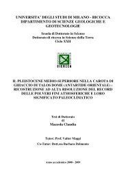
Figure 3.8: Contact mode AFM image <strong>of</strong> the surface <strong>of</strong> a (3 × 3) µm 2 region <strong>of</strong><br />
a <strong>rubrene</strong> thin film grown on top <strong>of</strong> a <strong>rubrene</strong> single crystal. (a) Height image<br />
in which lighter grays correspond to higher regions <strong>of</strong> the surface. (b) Deflection<br />
image collected on the same region, in which the grays scale is used to represent<br />
the cantilever deflection in each point.<br />
a value such that, during each oscillation, the tip passes from a non-contact<br />
regime to a contact regime, <strong>and</strong> then back to a non-contact regime.<br />
Variations in the average tip-sample distance lead to variations <strong>of</strong> the root<br />
mean square (RMS) oscillation amplitude <strong>of</strong> the cantilever. Thus, if during<br />
the scanning the tip encounters a valley or a protrusion on the sample sur-<br />
face there is a variation in the RMS oscillation amplitude <strong>of</strong> the cantilever.<br />
In analogy with what happens for contact-mode measurements, the feed-<br />
back circuit restores the initial oscillation amplitude by varying the vertical<br />
extension <strong>of</strong> the scanner. A morphological image <strong>of</strong> the surface can then<br />
be reconstructed by assigning to each image pixel the corresponding value<br />
<strong>of</strong> the scanner vertical extension. Height <strong>and</strong> amplitude images collected<br />
in tapping mode would look exactly like the height <strong>and</strong> deflection images<br />
reported in figure 3.8 <strong>and</strong> collected in contact mode.<br />
Since in tapping mode the AFM tip is in contact with sample surface<br />
only in the lowest point <strong>of</strong> the cantilever oscillation, the duration <strong>of</strong> the tip-<br />
sample interaction is minimized with respect to contact mode. This leads to<br />
the main advantage <strong>of</strong> tapping mode over contact mode measurements, i.e.<br />
minimum sample damage due to tip-sample interactions.<br />
During the scanning <strong>of</strong> a surface in tapping mode it is also possible<br />
to collect phase-contrast images, in addition to height images, constructed