Digital Fiber Sensor FS-N10 Series Instruction Manual 96M00603
Digital Fiber Sensor FS-N10 Series Instruction Manual 96M00603
Digital Fiber Sensor FS-N10 Series Instruction Manual 96M00603

Create successful ePaper yourself
Turn your PDF publications into a flip-book with our unique Google optimized e-Paper software.
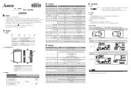
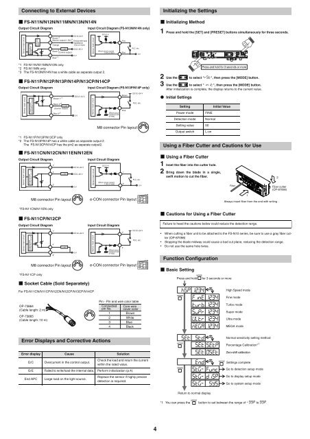
Connecting to External Devices<br />
<strong>FS</strong>-N11N/N12N/N11MN/N13N/N14N<br />
Output Circuit Diagram Input Circuit Diagram (<strong>FS</strong>-N13N/N14N only)<br />
<strong>Sensor</strong> main circuit<br />
*1 <strong>FS</strong>-N11N/N11MN/N13N only<br />
*2 <strong>FS</strong>-N11MN only<br />
*3 The <strong>FS</strong>-N13N/N14N has a white cable as separate output 2.<br />
<strong>FS</strong>-N11P/N12P/N13P/N14P/N13CP/N14CP<br />
Output Circuit Diagram Input Circuit Diagram (<strong>FS</strong>-N13P/N14P only)<br />
<strong>Sensor</strong> main circuit<br />
*1 <strong>FS</strong>-N11P/N13P/N13CP only<br />
*2 The <strong>FS</strong>-N13P/N14P has a white cable as separate output 2.<br />
The <strong>FS</strong>-N13CP/N14CP has the pin2 as separate output2.<br />
<strong>FS</strong>-N11CN/N12CN/N11EN/N12EN<br />
Output Circuit Diagram Input Circuit Diagram<br />
<strong>Sensor</strong> main circuit<br />
*<strong>FS</strong>-N11CN/N11EN only<br />
<strong>FS</strong>-N11CP/N12CP<br />
Output Circuit Diagram Input Circuit Diagram<br />
<strong>Sensor</strong> main circuit<br />
Overcurrent<br />
protection<br />
circuit<br />
Overcurrent<br />
protection circuit<br />
Overcurrent<br />
protection circuit<br />
Overcurrent<br />
protection circuit<br />
Protection<br />
circuit<br />
*<strong>FS</strong>-N11CP only<br />
DC12−24 V<br />
Brown*<br />
DC5−30 V<br />
0 V<br />
1<br />
Black* 3<br />
Monitor output(1−5V)* 2<br />
Device with input<br />
impedance<br />
Orange<br />
10 Ω or more<br />
Load<br />
Blue* 1<br />
(Control output)<br />
Brown 1* 1<br />
Black 4* 2<br />
Load<br />
(Control output)<br />
1*<br />
4<br />
3*<br />
Blue 3* 1<br />
Load<br />
DC12−24 V<br />
Socket Cable (Sold Separately)<br />
For <strong>FS</strong>-N11CN/N11CP/N12CN/N12CP/N13CP/N14CP<br />
Error Displays and Corrective Actions<br />
Error display Cause Solution<br />
ErC Overcurrent in the control output.<br />
Check the load and return the current<br />
within the rated value.<br />
ErE Failed to write/load the internal data. Perform initialization (p.4).<br />
End APC Large load on the light source.<br />
0 V<br />
DC12−24 V<br />
DC5−30 V<br />
0 V<br />
2<br />
1<br />
4<br />
3<br />
<strong>Sensor</strong> main circuit<br />
<strong>Sensor</strong> main circuit<br />
<strong>Sensor</strong> main circuit<br />
DC3.3 V<br />
(Short-circuit current<br />
1 mA or less)<br />
(Short-circuit<br />
current 2 mA<br />
or less)<br />
Pink<br />
Blue<br />
Brown<br />
Pink<br />
PLC, etc.<br />
0 V<br />
DC12−24 V<br />
PLC, etc.<br />
M8 connector Pin layout<br />
DC3.3 V<br />
(Short-circuit current<br />
1 mA or less)<br />
M8 connector Pin layout e-CON connector Pin layout<br />
1*<br />
4<br />
3*<br />
Load<br />
DC12−24 V<br />
0 V<br />
2<br />
1<br />
4<br />
3<br />
<strong>Sensor</strong> main circuit<br />
(Short-circuit<br />
current 2 mA<br />
or less)<br />
M8 connector Pin layout e-CON connector Pin layout<br />
OP-73864<br />
(Cable length: 2 m)<br />
OP-73865<br />
(Cable length: 10 m)<br />
4 2<br />
3 1<br />
2<br />
1<br />
4<br />
3<br />
Replace the sensor if highly precise<br />
detection is required.<br />
2<br />
1<br />
3*<br />
1*<br />
PLC, etc.<br />
0 V<br />
DC12−24 V<br />
PLC, etc.<br />
Pin - Pin and wire color table<br />
Connected Core wire<br />
pin No. cover color<br />
1 Brown<br />
2<br />
3<br />
4<br />
White<br />
Blue<br />
Black<br />
4<br />
Initializing the Settings<br />
Initializing Method<br />
1 Press and hold the [SET] and [PRESET] buttons simultaneously for three seconds.<br />
2 Use the to select "", then press the [MODE] button.<br />
3 Use the to select "", then press the [MODE] button.<br />
After initialization is complete, the display returns to the current value.<br />
Initial Settings<br />
Using a <strong>Fiber</strong> Cutter and Cautions for Use<br />
Using a <strong>Fiber</strong> Cutter<br />
1 Inset the fiber into the cutter hole.<br />
2 Bring down the blade in a single,<br />
swift motion to cut the fiber.<br />
Cautions for Using a <strong>Fiber</strong> Cutter<br />
• When cutting a fiber unit to be attached to the <strong>FS</strong>-<strong>N10</strong> series, be sure to use a gray fiber cutter<br />
(OP-87098)<br />
• Stopping the blade midway could cause a bad cut plane, reducing the detection range.<br />
• Do not use the same hole twice.<br />
Function Configuration<br />
Basic Setting<br />
Setting Initial Value<br />
Power mode FINE<br />
Detection mode Normal<br />
Setting value 50<br />
Output switch L-on<br />
Press and hold for 3 seconds or more<br />
<strong>Fiber</strong><br />
Always insert fiber from the end with writing<br />
Failure to heed the cautions below could reduce the detection range.<br />
MODE<br />
Press and hold for 3 seconds or more<br />
<br />
<br />
<br />
<br />
<br />
<br />
MODE<br />
MODE<br />
MODE<br />
<br />
<br />
<br />
<br />
<br />
<br />
<br />
<br />
Return to normal display<br />
MODE<br />
MODE<br />
*1 You can press the button to set between the range of to .<br />
1<br />
High Speed mode<br />
Fine mode<br />
Turbo mode<br />
Super mode<br />
Ultra mode<br />
MEGA mode<br />
Normal sensitivity setting method<br />
Percentage Calibration* 1<br />
Zero-shift calibration<br />
Settings complete<br />
Go to detection setup mode<br />
Go to display setup mode<br />
Go to system setup mode<br />
2<br />
<strong>Fiber</strong> cutter<br />
(OP-87098)