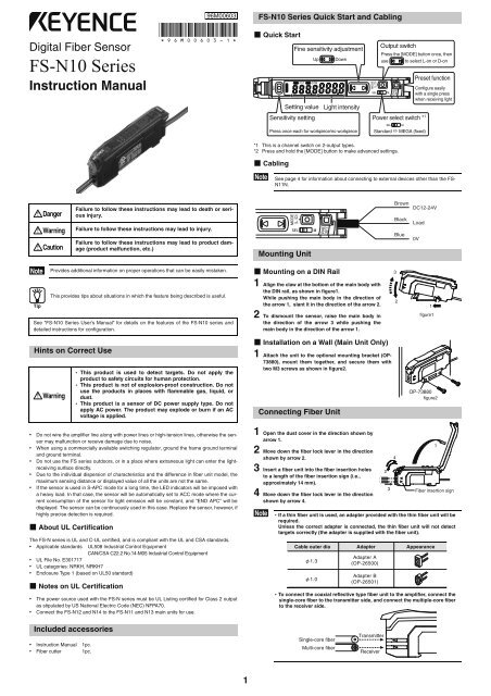
Digital Fiber Sensor FS-N10 Series Instruction Manual 96M00603
Digital Fiber Sensor FS-N10 Series Instruction Manual 96M00603
Digital Fiber Sensor FS-N10 Series Instruction Manual 96M00603

You also want an ePaper? Increase the reach of your titles
YUMPU automatically turns print PDFs into web optimized ePapers that Google loves.
Connecting Multiple Amplifiers<br />
Up to 16 sub units can be connected to one main unit.<br />
Note<br />
Warning<br />
1 Remove the protection covers of the main unit and<br />
sub unit(s).<br />
2 Install the amplifiers one by one on the DIN rail.<br />
3 Engage the two claws of the sub unit with the<br />
recesses on the main unit side until you hear a<br />
click.<br />
4 Attach the end units (option: OP-26751) to the<br />
both ends of the connected amplifiers in the same<br />
way as in step (2).<br />
5 Sandwich the amplifiers between the end units.<br />
Tighten the screws at the top (two screws x two<br />
units) with a Phillips screwdriver to fix the end<br />
units.<br />
Calibration Method<br />
Mount on DIN rail and install on metal sheeting when connecting to<br />
multiple amplifiers or mounting main units together.<br />
• Multiple connections cannot be made to equipment other than the <strong>FS</strong>-<strong>N10</strong><br />
series.<br />
• Turn the power off before connecting multiple sub units.<br />
• Do not touch the expansion connector with your bare hands.<br />
Detecting Even Small Differences<br />
Two-point Calibration<br />
Two-point calibration is the basic method for making calibration.<br />
You can set the sensitivity level automatically, simply by pressing the [SET] button twice.<br />
Just press once with the workpiece set up, and once without.<br />
Through-beam model setting method<br />
Workpiece<br />
Reflective model setting method<br />
Workpiece<br />
OP-26751 (a set of two)<br />
Press [SET] button once with<br />
no workpiece set<br />
Press [SET] button once with<br />
workpiece set<br />
Settings complete<br />
Press [SET] button once with<br />
no workpiece set<br />
Press [SET] button once with<br />
workpiece set<br />
Settings complete<br />
2<br />
Two-point calibration performs detection at a location where there is a workpiece, and<br />
another location where there is not, uses the intermediate value as the setting.<br />
If the sensitivity difference does not have enough room, "- - - -" flashes for about two seconds<br />
after the calibration is complete. The set value is stored in memory even in that case.<br />
Other Calibration Methods<br />
Increase Resistance to Dust and Dirt<br />
Maximum Sensitivity Setting<br />
In the state shown below, press and hold the [SET] button for three seconds and stop pushing<br />
when "" flashes.<br />
The sensitivity is set slightly higher than the light intensity.<br />
Through-beam model : with workpiece set<br />
Workpiece<br />
Reflective model : without workpiece set<br />
Calibrate with Moving Workpiece<br />
Full Auto Calibration<br />
Press and hold the [SET] button with no workpiece in place, while “” is flashing, pass<br />
through a workpiece. (Continue pressing the [SET] button while the workpiece passes<br />
through.)<br />
Common to<br />
Through-beam and Reflective Models<br />
Position Workpiece<br />
Positioning Calibration<br />
Workpiece<br />
Press and hold for 3 seconds or more<br />
Press and hold for 3 seconds or more<br />
Press and hold until<br />
"" flashes<br />
While pressing the [SET] button<br />
pass through a workpiece<br />
Settings complete<br />
Press the [SET] button with no workpiece set.<br />
Place the workpiece in the location you wish to position it, and press and hold the [SET] button<br />
for at least 3 seconds. Release the button when "" flashes.<br />
Common to<br />
Through-beam and Models<br />
Reflective<br />
Workpiece<br />
Press [SET] button once with<br />
no workpiece set<br />
Press and hold [SET] button with<br />
workpiece set<br />
Press and hold until<br />
"" flashes<br />
Settings complete
Simple, User Friendly Functions<br />
Easily Set up Display<br />
Preset Function<br />
With light ON, press the [PRESET] button. The current value is set to "".<br />
Pressing the [PRESET] button changes the setting and current value as shown below.<br />
• Presetting with preset disabled:<br />
The setting is changed to "". The setting can be changed via the normal calibration<br />
method.<br />
• Presetting with preset enabled:<br />
Only the current value is changed to "", and the setting is not changed.<br />
Note<br />
Disable the Preset Function<br />
Press and hold the [PRESET] button to disable the preset function.<br />
When the preset function is disabled, the ratio of the setting and current values is maintained<br />
as-is.<br />
Note<br />
Tip<br />
• The preset function cannot be used together with the zero shift function.<br />
To use the zero shift function, you must first disable the preset<br />
function.<br />
• This is not suited to transparent workpieces and other cases of detection<br />
with low light shielding.<br />
Handy Uses for the Preset Function<br />
This function is mainly useful when performing simple detection using a<br />
through-beam model fiber unit (e.g. complete dark detection, such as when all<br />
light axes of the fiber unit are shielded with opaque workpieces).<br />
When you are using multiple <strong>FS</strong>-<strong>N10</strong> series units simultaneously, this function<br />
is an easy way to make all the displays uniform.<br />
Set Current Value to "0"<br />
The Zero Shift Function<br />
This function is mainly used with reflective models.<br />
Press the [PRESET] button and [ ] button at the same time.<br />
The current value is set to "0".<br />
Note<br />
Press [PRESET] button once<br />
with no workpiece set<br />
Setting is<br />
""<br />
Green "PST" lights up<br />
The zero shift and preset function cannot be used together. To use<br />
the preset function, you must first disable the zero shift function.<br />
Disable the Zero Shift Function<br />
Press and hold the [PRESET] button to disable the zero shift function.<br />
Note<br />
Tip<br />
Current value is<br />
""<br />
Green "PST" lights up<br />
Current value is ""<br />
Handy Uses for the Zero Shift Function<br />
This function is mainly used to set the current value to "0" on a reflective<br />
model fiber unit.<br />
When a reflective model is first installed, the light intensity is sometimes not<br />
set to "0".<br />
If this happens, using the zero shift function to set the value to "0" when there<br />
is no workpiece allows for easier understanding of the difference in light intensity.<br />
3<br />
Set the current value to an adequate value when it is too<br />
large (when saturated).<br />
Use the Saturation Recovery Function<br />
Press the [SET] button while pressing the [MODE] button to enable the saturation recovery<br />
function.<br />
The light transmission level and light intensity gain are calibrated automatically.<br />
Disable Saturation Recovery<br />
When the saturation recovery function is enabled, press the [SET] button while pressing the<br />
[MODE] button to cancel it.<br />
Note<br />
Tip<br />
Output Switch<br />
Power mode Light intensity setting range<br />
HSP, FINE, TURBO 2047 350<br />
SUPER 4095 500<br />
ULTRA, MEGA 5000 600<br />
Handy Uses for the Saturation Recovery Function<br />
This function is handy when the fiber unit becomes saturated after installation.<br />
This eliminates the saturation via a simple operation, by automatically calibrating<br />
the light transmission level and light intensity gain.<br />
Either light-ON (L-on) mode or dark-ON (D-on) mode can be selected.<br />
1 While the current value is displayed, press the [MODE] button once.<br />
2 Use to switch the output (/), then press the [MODE] button again.<br />
The output switch completes, and the display returns to the current value.<br />
Names of Each Part of the Main Unit<br />
<strong>Fiber</strong> lock lever<br />
SET button (SET)<br />
Operation status indicators<br />
PST indicator<br />
DTM indicator<br />
<strong>Digital</strong> monitor<br />
<strong>Manual</strong> button<br />
( )<br />
Press the [SET] button while<br />
pressing the [MODE] button.<br />
Set the light intensity to<br />
within the range in the table below.<br />
Setting value<br />
(Displayed in green)<br />
Current value<br />
(Displayed in red)<br />
MODE button (MODE)<br />
Power select switch*<br />
Dust cover<br />
1<br />
Cable* 2<br />
Expansion<br />
protective cover<br />
Expansion connector<br />
Preset button (PRESET)<br />
*1 Setting to "M" locks the power mode to MEGA mode. The two output type is a channel<br />
switch.<br />
*2 On the <strong>FS</strong>-<strong>N10</strong>Cx, this is an M8 connector rather than a cable. On the <strong>FS</strong>-<strong>N10</strong>Ex, this is an<br />
e-CON connector.
Connecting to External Devices<br />
<strong>FS</strong>-N11N/N12N/N11MN/N13N/N14N<br />
Output Circuit Diagram Input Circuit Diagram (<strong>FS</strong>-N13N/N14N only)<br />
<strong>Sensor</strong> main circuit<br />
*1 <strong>FS</strong>-N11N/N11MN/N13N only<br />
*2 <strong>FS</strong>-N11MN only<br />
*3 The <strong>FS</strong>-N13N/N14N has a white cable as separate output 2.<br />
<strong>FS</strong>-N11P/N12P/N13P/N14P/N13CP/N14CP<br />
Output Circuit Diagram Input Circuit Diagram (<strong>FS</strong>-N13P/N14P only)<br />
<strong>Sensor</strong> main circuit<br />
*1 <strong>FS</strong>-N11P/N13P/N13CP only<br />
*2 The <strong>FS</strong>-N13P/N14P has a white cable as separate output 2.<br />
The <strong>FS</strong>-N13CP/N14CP has the pin2 as separate output2.<br />
<strong>FS</strong>-N11CN/N12CN/N11EN/N12EN<br />
Output Circuit Diagram Input Circuit Diagram<br />
<strong>Sensor</strong> main circuit<br />
*<strong>FS</strong>-N11CN/N11EN only<br />
<strong>FS</strong>-N11CP/N12CP<br />
Output Circuit Diagram Input Circuit Diagram<br />
<strong>Sensor</strong> main circuit<br />
Overcurrent<br />
protection<br />
circuit<br />
Overcurrent<br />
protection circuit<br />
Overcurrent<br />
protection circuit<br />
Overcurrent<br />
protection circuit<br />
Protection<br />
circuit<br />
*<strong>FS</strong>-N11CP only<br />
DC12−24 V<br />
Brown*<br />
DC5−30 V<br />
0 V<br />
1<br />
Black* 3<br />
Monitor output(1−5V)* 2<br />
Device with input<br />
impedance<br />
Orange<br />
10 Ω or more<br />
Load<br />
Blue* 1<br />
(Control output)<br />
Brown 1* 1<br />
Black 4* 2<br />
Load<br />
(Control output)<br />
1*<br />
4<br />
3*<br />
Blue 3* 1<br />
Load<br />
DC12−24 V<br />
Socket Cable (Sold Separately)<br />
For <strong>FS</strong>-N11CN/N11CP/N12CN/N12CP/N13CP/N14CP<br />
Error Displays and Corrective Actions<br />
Error display Cause Solution<br />
ErC Overcurrent in the control output.<br />
Check the load and return the current<br />
within the rated value.<br />
ErE Failed to write/load the internal data. Perform initialization (p.4).<br />
End APC Large load on the light source.<br />
0 V<br />
DC12−24 V<br />
DC5−30 V<br />
0 V<br />
2<br />
1<br />
4<br />
3<br />
<strong>Sensor</strong> main circuit<br />
<strong>Sensor</strong> main circuit<br />
<strong>Sensor</strong> main circuit<br />
DC3.3 V<br />
(Short-circuit current<br />
1 mA or less)<br />
(Short-circuit<br />
current 2 mA<br />
or less)<br />
Pink<br />
Blue<br />
Brown<br />
Pink<br />
PLC, etc.<br />
0 V<br />
DC12−24 V<br />
PLC, etc.<br />
M8 connector Pin layout<br />
DC3.3 V<br />
(Short-circuit current<br />
1 mA or less)<br />
M8 connector Pin layout e-CON connector Pin layout<br />
1*<br />
4<br />
3*<br />
Load<br />
DC12−24 V<br />
0 V<br />
2<br />
1<br />
4<br />
3<br />
<strong>Sensor</strong> main circuit<br />
(Short-circuit<br />
current 2 mA<br />
or less)<br />
M8 connector Pin layout e-CON connector Pin layout<br />
OP-73864<br />
(Cable length: 2 m)<br />
OP-73865<br />
(Cable length: 10 m)<br />
4 2<br />
3 1<br />
2<br />
1<br />
4<br />
3<br />
Replace the sensor if highly precise<br />
detection is required.<br />
2<br />
1<br />
3*<br />
1*<br />
PLC, etc.<br />
0 V<br />
DC12−24 V<br />
PLC, etc.<br />
Pin - Pin and wire color table<br />
Connected Core wire<br />
pin No. cover color<br />
1 Brown<br />
2<br />
3<br />
4<br />
White<br />
Blue<br />
Black<br />
4<br />
Initializing the Settings<br />
Initializing Method<br />
1 Press and hold the [SET] and [PRESET] buttons simultaneously for three seconds.<br />
2 Use the to select "", then press the [MODE] button.<br />
3 Use the to select "", then press the [MODE] button.<br />
After initialization is complete, the display returns to the current value.<br />
Initial Settings<br />
Using a <strong>Fiber</strong> Cutter and Cautions for Use<br />
Using a <strong>Fiber</strong> Cutter<br />
1 Inset the fiber into the cutter hole.<br />
2 Bring down the blade in a single,<br />
swift motion to cut the fiber.<br />
Cautions for Using a <strong>Fiber</strong> Cutter<br />
• When cutting a fiber unit to be attached to the <strong>FS</strong>-<strong>N10</strong> series, be sure to use a gray fiber cutter<br />
(OP-87098)<br />
• Stopping the blade midway could cause a bad cut plane, reducing the detection range.<br />
• Do not use the same hole twice.<br />
Function Configuration<br />
Basic Setting<br />
Setting Initial Value<br />
Power mode FINE<br />
Detection mode Normal<br />
Setting value 50<br />
Output switch L-on<br />
Press and hold for 3 seconds or more<br />
<strong>Fiber</strong><br />
Always insert fiber from the end with writing<br />
Failure to heed the cautions below could reduce the detection range.<br />
MODE<br />
Press and hold for 3 seconds or more<br />
<br />
<br />
<br />
<br />
<br />
<br />
MODE<br />
MODE<br />
MODE<br />
<br />
<br />
<br />
<br />
<br />
<br />
<br />
<br />
Return to normal display<br />
MODE<br />
MODE<br />
*1 You can press the button to set between the range of to .<br />
1<br />
High Speed mode<br />
Fine mode<br />
Turbo mode<br />
Super mode<br />
Ultra mode<br />
MEGA mode<br />
Normal sensitivity setting method<br />
Percentage Calibration* 1<br />
Zero-shift calibration<br />
Settings complete<br />
Go to detection setup mode<br />
Go to display setup mode<br />
Go to system setup mode<br />
2<br />
<strong>Fiber</strong> cutter<br />
(OP-87098)
Detection Settings<br />
*6<br />
*7<br />
MODE<br />
MODE<br />
<br />
MODE<br />
<br />
MODE<br />
<br />
<br />
<br />
<br />
MODE<br />
<br />
<br />
<br />
<br />
<br />
<br />
MODE<br />
<br />
<br />
<br />
<br />
<br />
<br />
<br />
<br />
<br />
*4 Can be set between the range of and .<br />
*5 Can be set between the range of and .<br />
*6 Only external input types (<strong>FS</strong>-N11CN/N11CP/N11EN/N12EN/N13N/N13P/N14N/N14P).<br />
*7 Only monitor output types (<strong>FS</strong>-N11MN).<br />
Display Settings<br />
<br />
<br />
<br />
<br />
MODE<br />
<br />
<br />
<br />
Timer OFF<br />
Off-delay timer * 1<br />
On-delay timer * 1<br />
One-shot timer * 1<br />
Normal (light intensity)<br />
detection mode<br />
DATUM1 mode * 2<br />
DATUM2 mode * 2<br />
Area detection mode<br />
Rising Edge Detection Mode<br />
Falling Edge Detection Mode<br />
Do not use external input<br />
External calibration input<br />
Preset input<br />
Zero shift input<br />
Reset input<br />
Transmission OFF input<br />
Pause mode transition input * 3<br />
Sleep mode transition input<br />
Light emission power selection * 4<br />
Analog scaling * 5<br />
Settings complete<br />
Go to display setup mode<br />
Go to system setup mode<br />
Return to original<br />
detection setup mode<br />
Return to normal display<br />
MODE<br />
*1 Press the button to set between the range of and (ms).<br />
MODE<br />
*2 Press the button to set the retouch sensitivity to a range of between and <br />
and set the warning output level to a range of between and .<br />
MODE<br />
*3 Press the button to toggle between //.<br />
<br />
MODE<br />
<br />
MODE<br />
<br />
<br />
MODE<br />
<br />
<br />
<br />
<br />
<br />
<br />
<br />
MODE<br />
<br />
<br />
MODE<br />
<br />
<br />
<br />
Normal display method<br />
Reverse display<br />
Do not set up sub-display<br />
Extension display<br />
Bar display<br />
Excess gain display<br />
Light intensity hold display * 1<br />
Excess gain hold display * 1<br />
L-on / D-on display<br />
Enable the saturation of the<br />
Preset function * 2<br />
Disable the saturation of the<br />
Preset function<br />
Settings complete<br />
Go to system setup mode<br />
Go to detection setup mode<br />
Return to original display setup mode<br />
Return to normal display<br />
MODE<br />
*1 Press the button to toggle between ////<br />
MODE<br />
*2 Press the button to set between the range of and .<br />
5<br />
System Settings<br />
*1<br />
<br />
MODE<br />
MODE<br />
MODE<br />
MODE<br />
<br />
*1 Main unit only.<br />
Two Output *2<br />
MODE<br />
MODE<br />
<br />
<br />
<br />
<br />
<br />
<br />
<br />
MODE<br />
<br />
<br />
MODE<br />
<br />
<br />
MODE<br />
<br />
<br />
<br />
<br />
<br />
<br />
Return to normal display<br />
<br />
<br />
<br />
Disable APC<br />
Enable APC<br />
Do not use eco feature<br />
Enable eco feature<br />
Reduce power consumption<br />
(response time 4 times slower)<br />
Standard current value display<br />
Maximum current value display<br />
(4 times hysteresis)<br />
Normal operation<br />
Twice number of<br />
interference-prevention units as <br />
(response time 2 times slower)<br />
Disable common key operations<br />
Enable common key operations<br />
Settings complete<br />
<br />
<br />
<br />
<br />
MODE<br />
<br />
<br />
<br />
<br />
MODE<br />
Go to detection setup mode<br />
Go to original display setup mode<br />
Return to system setup mode<br />
Light intensity detection mode<br />
Limit setting output mode<br />
User reset<br />
Auto reset<br />
Warning output mode<br />
Timer OFF<br />
Off-delay timer * 1<br />
On-delay timer * 1<br />
One-shot timer * 1<br />
Settings complete<br />
Return to normal display<br />
MODE<br />
*1 Press the button to set between the range of and (ms).<br />
*2 Only 2 output types (<strong>FS</strong>-N13N/N13P/N14N/N14P/N13CP/N14CP).
Specifications<br />
Type<br />
*1 Use a cable length of 30m or less for M8 connector and e-CON connector types.<br />
*2 Increases 100 mW (4.0 mA) for High Speed mode<br />
*3 One or two more units connected: -10 to +55C; 3 to 10 more units connected: -10 to +50C; 11 to 16 more units connected: -10 to +45C. When using 2-outputs, one unit is counted as two units.<br />
All temperature regulations are for when the unit is mounted on a DIN rail and installed on metal sheeting.<br />
Warranties and Disclaimers<br />
Standard 1 output<br />
KEYENCE, at its sole option, will refund, repair or replace at no charge any defective Products<br />
within 1 year from the date of shipment. Unless stated otherwise herein, the Products should<br />
not be used internally in humans, for human transportation, as safety devices or fail-safe systems.<br />
EXCEPT FOR THE FOREGOING, ALL EXPRESS, IMPLIED AND STATUTORY WAR-<br />
RANTIES, INCLUDING WARRANTIES OF MERCHANTABILITY, FITNESS FOR A<br />
PARTICULAR PURPOSE AND NONINFRINGEMENT OF PROPRIETARY RIGHTS, ARE<br />
EXPRESSLY DISCLAIMED. KEYENCE SHALL NOT BE LIABLE FOR ANY DIRECT, INDI-<br />
RECT, INCIDENTAL, CONSEQUENTIAL OR OTHER DAMAGES, EVEN IF DAMAGES<br />
RESULT FROM THE USE OF THE PRODUCTS IN ACCORDANCE WITH ANY SUGGES-<br />
TIONS OR INFORMATION PROVIDED BY KEYENCE. In some jurisdictions, some of the foregoing<br />
warranty disclaimers or damage limitations may not apply.<br />
6<br />
Monitor<br />
output<br />
High functionality 2 output<br />
Cable/M8 connector Cable M8 connector *1 e-CON connector *1 Cable Cable M8 connector *1<br />
Main unit/sub unit<br />
Main unit<br />
Sub unit<br />
(with output<br />
cable)<br />
Main unit<br />
Sub unit<br />
(with output<br />
cable)<br />
Main unit<br />
Sub unit<br />
(with output<br />
cable)<br />
Main unit Main unit<br />
Sub unit<br />
(with output<br />
cable)<br />
Model NPN <strong>FS</strong>-N11N <strong>FS</strong>-N12N <strong>FS</strong>-N11CN <strong>FS</strong>-N12CN <strong>FS</strong>-N11EN <strong>FS</strong>-N12EN <strong>FS</strong>-N11MN <strong>FS</strong>-N13N <strong>FS</strong>-N14N - -<br />
Main unit<br />
Sub unit<br />
(with output<br />
cable)<br />
PNP <strong>FS</strong>-N11P <strong>FS</strong>-N12P <strong>FS</strong>-N11CP <strong>FS</strong>-N12CP - - - <strong>FS</strong>-N13P <strong>FS</strong>-N14P <strong>FS</strong>-N13CP <strong>FS</strong>-N14CP<br />
Control output 1 output 1 output 1 output 1 output 1 output 1 output 1 output 2 output 2 output 2 output 2 output<br />
Monitor output (1-5 V) - - - - - - 1 output - - - -<br />
External input - - 1 input 1 input 1 input 1 input - 1 input 1 input - -<br />
Response time 50 s (HIGH SPEED)/250 s (FINE)/500 s (TURBO)/1 ms (SUPER)/4 ms (ULTRA)/16 ms (MEGA)<br />
Control<br />
output<br />
NPN output NPN open collector 30 V; 1 output max: 100 mA or less; 2 output total:<br />
100 mA or less (used stand-alone)/20 mA or less (multiple connections); residual voltage 1 V or less<br />
PNP output PNP open collector 30 V; 1 output max: 100 mA or less; 2 output total:<br />
100 mA or less (used stand-alone)/20 mA or less (multiple connections); residual voltage 1 V or less<br />
Monitor output 1 to 5 V voltage output; load resistance 10 k or more; repeat precision 0.5% of F.S.; responsiveness 1 ms (<strong>FS</strong>-N11MN only)<br />
External input input time 2 ms (ON)/20 ms (OFF) or more<br />
Multiple connections to sub<br />
units<br />
Number of interference<br />
prevention units<br />
Up to 16 units can be connected total, but two-output type is treated as two units<br />
0 for HSP; 4 for FINE; 8 for TURBO/SUPER/ULTRA/MEGA (When set to double, the number of interference-prevention units will be doubled.)<br />
Rating Power voltage 12 - 24 V DC 10% ripple (P-P) 10% or less<br />
Environme<br />
ntal<br />
resistance<br />
NPN Normal:900 mW or less (36 mA max. at 24 V, 48 mA max. at 12 V) *2<br />
Eco on mode:800 mW or less (32 mA max. at 24 V, 39 mA max. at 12 V) *2<br />
Eco Full mode:470 mW or less (19 mA max. at 24 V, 23 mA max. at 12 V)<br />
PNP<br />
Operating<br />
ambient<br />
luminance<br />
Operating<br />
ambient<br />
temperature<br />
Operating<br />
ambient<br />
humidity<br />
Vibration<br />
resistance<br />
Shock<br />
resistance<br />
Normal : 950 mW or less (39 mA max. at 24 V, 52 mA max. at 12 V) *2<br />
Eco on mode : 850 mW or less (35 mA max. at 24 V, 44 mA max. at 12 V) *2<br />
Eco Full mode : 520 mW or less (21 mA max. at 24 V, 26 mA max. at 12 V)<br />
Incandescent lamp: 20,000 lx or less; Sunlight: 30,000 lx or less<br />
-10 to +55 C (no freezing) *3<br />
35 to 85% RH (no condensation)<br />
10 to 55 Hz Compound amplitude 1.5 mm, 2 hours for each of X,Y,Z axis<br />
500 m/s 2 3 times for each of X,Y,Z axis<br />
Case material Both main unit and housing material: Polycarbonate<br />
-<br />
Normal : 1050 mW or less(42 mA max. at 24 V,<br />
56 mA max. at 12 V) *2<br />
Eco on mode : 950 mW or less(38 mA max. at 24 V,<br />
47 mA max. at 12 V) *2<br />
Eco Full mode : 600 mW or less(24 mA max. at 24 V,<br />
29 mA max. at 12 V)<br />
Weight Approx 75g Approx 45g Approx 22g Approx 22g Approx 22g Approx 22g Approx 75g Approx 80g Approx 70g Approx 22g Approx 22g<br />
KEYENCE CORPORATION<br />
1-3-14, Higashi-Nakajima, Higashi-Yodogawa-ku,<br />
Osaka, 533-8555, Japan<br />
PHONE: +81-6-6379-2211<br />
AUSTRIA<br />
Phone: +43-2236-378266-0<br />
BELGIUM<br />
Phone: +32 2 716 40 63<br />
CANADA<br />
Phone: +1-905-696-9970<br />
CHINA<br />
Phone: +86-21-68757500<br />
CZECH REPUBLIC<br />
Phone: +420 222 191 483<br />
FRANCE<br />
Phone: +33 1 56 37 78 00<br />
GERMANY<br />
Phone: +49-6102-36 89-0<br />
HONG KONG<br />
Phone: +852-3104-1010<br />
HUNGARY<br />
Phone: +36 14 748 313<br />
ITALY<br />
Phone: +39-2-6688220<br />
JAPAN<br />
Phone: +81-6-6379-2211<br />
KOREA<br />
Phone: +82-31-642-1270<br />
MALAYSIA<br />
Phone: +60-3-2092-2211<br />
MEXICO<br />
Phone: +52-81-8220-7900<br />
NETHERLANDS<br />
Phone: +31 40 20 66 100<br />
POLAND<br />
Phone: +48 71 36861 60<br />
Specifications are subject to change without notice.<br />
Copyright (c) 2009 KEYENCE CORPORATION. All rights reserved.<br />
00603E 0079-1 <strong>96M00603</strong> Printed in Japan<br />
www.keyence.com<br />
SINGAPORE<br />
Phone: +65-6392-1011<br />
SLOVAKIA<br />
Phone: +421 2 5939 6461<br />
SWITZERLAND<br />
Phone: +41 43 455 77 30<br />
TAIWAN<br />
Phone: +886-2-2718-8700<br />
THAILAND<br />
Phone: +66-2-369-2777<br />
UK & IRELAND<br />
Phone: +44-1908-696900<br />
USA<br />
Phone: +1-201-930-0100<br />
A6WW1-MAN-0059