Interrupts
Interrupts
Interrupts

You also want an ePaper? Increase the reach of your titles
YUMPU automatically turns print PDFs into web optimized ePapers that Google loves.
Microprocessor Fundamentals<br />
Topic 16<br />
<strong>Interrupts</strong>
Objectives<br />
• To become familiar with interrupts on the AVR<br />
– Maskable and non-maskable<br />
– Initialization<br />
– Triggers<br />
• To develop interrupt service routines (ISRs) to<br />
handle interrupts<br />
• To understand the sequence of events that occur<br />
when an IRQ occurs<br />
1/4/2010 2
<strong>Interrupts</strong><br />
• <strong>Interrupts</strong> are asynchronous changes in program<br />
flow that occur as a result of events outside the<br />
running program<br />
– They are usually hardware related:<br />
• Examples: button press, timer expiration, peripheral device<br />
needs data, etc<br />
– Interrupt conditions are independent of the program:<br />
• <strong>Interrupts</strong> can happen at any time (asynchronous)<br />
1/4/2010 3
Why use interrupts?<br />
• As programs (or systems) grow it becomes very<br />
difficult to predict/ensure that time-critical events<br />
are handled properly<br />
– Example:<br />
• An external device sends data to the processor<br />
• The processor must read the data before that data is<br />
overwritten<br />
– This is typical in serial data transmission<br />
1/4/2010 4
Maskable/Non-maskable<br />
• <strong>Interrupts</strong> in general can be divided into two<br />
kinds- maskable and non-maskable.<br />
– A maskable interrupt is an interrupt whose trigger<br />
event is not always important:<br />
• The program can decide if the event should be recognized or<br />
ignored and can be disabled/enabled<br />
– A non-maskable interrupt is so important that it should<br />
never be ignored<br />
• The processor will always jump to this interrupt when it<br />
happens<br />
• The reset button is an example<br />
1/4/2010 5
<strong>Interrupts</strong> on the ATmega128<br />
• External interrupt inputs are pins INT7 - INT0<br />
1/4/2010<br />
– They are triggered by:<br />
• A high-to-low transition (a falling edge) on one of these<br />
pins<br />
• A low-to-high transition (a rising edge) on one of these<br />
pins<br />
• A low level on one of these pins<br />
– They are initialized by:<br />
• External Interrupt Control Registers<br />
– EICRA for INT3:0<br />
– EICRB for INT7:4<br />
6
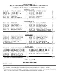
EICRA INT3 - 0<br />
• External Interrupt Control Register A<br />
1/4/2010<br />
INT3 Control<br />
INT2 Control<br />
INT1 Control<br />
INT0 Control<br />
7
EICRA INT3 - 0<br />
• External Interrupt Control Register A<br />
1/4/2010<br />
INT3 Control<br />
INT2 Control<br />
INT1 Control<br />
INT0 Control<br />
If initialized for low-level triggering, the pin must be held low for a minimum of 50 ns<br />
AND until the most recent instruction is completed.<br />
8
EICRA INT3 - 0<br />
1/4/2010<br />
Exercise: What value must be stored in EICRA to initialize INT3 and INT0 for<br />
low-to-high transitions, INT2 for low level, and INT1 for high-to—low<br />
transitions?<br />
9
EICRA INT3 - 0<br />
1/4/2010<br />
1 1 0 0 1 0 1 1<br />
Exercise: What value must be stored in EICRA to initialize INT3 and INT0 for<br />
low-to-high transitions, INT2 for low level, and INT1 for high-to-low transitions?<br />
Ans: 1100 1011 or $CB<br />
10
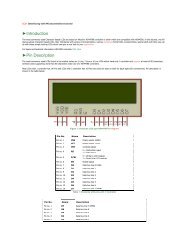
Pins<br />
• INT3:0<br />
External <strong>Interrupts</strong> 3 – 0 are<br />
alternate functions of Port D<br />
1/4/2010<br />
11
Pins<br />
• INT3:0<br />
External <strong>Interrupts</strong> 3 – 0 are<br />
alternate functions of Port D<br />
They are enabled if the I-flag<br />
in the Status Register is set<br />
(1) and the corresponding<br />
interrupt mask bit in the<br />
EIMSK is set (1).<br />
1/4/2010<br />
12
Pins<br />
• INT3:0<br />
When the appropriate signal transition occurs on one of the external interrupt pins<br />
(INT7:0) an interrupt request (IRQ) is triggered and the corresponding bit in the<br />
EIFR register (Interrupt Flag Register) gets set.<br />
The flag is cleared when the interrupt routine is executed.<br />
Alternatively, the flag can be cleared by writing a logical one to it.<br />
These flags are always cleared when INT7:0 are configured as level interrupt.<br />
1/4/2010<br />
13
Pins<br />
• INT3:0<br />
Exercise: I want to clear the flag for INT1 (the others I don’t want to change). What<br />
value must I write to this register?<br />
1/4/2010<br />
14
Pins<br />
• INT3:0<br />
Exercise: I want to clear the flag for INT1 (the others I don’t want to change). What<br />
value must I write to this register?<br />
Ans: 0000 0010 or $02<br />
1/4/2010<br />
15
EICRB INT7 - 4<br />
• External Interrupt Control Register B<br />
1/4/2010<br />
INT3 Control<br />
INT2 Control<br />
INT1 Control<br />
INT0 Control<br />
16
Pins<br />
• Bits 7 - 4<br />
External <strong>Interrupts</strong> 7 – 4 are<br />
alternate functions of Port E<br />
They are enabled if the I-flag<br />
in the Status Register is set<br />
(1) and the corresponding<br />
interrupt mask bit in the<br />
EIMSK is set (1).<br />
1/4/2010<br />
17
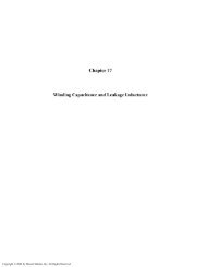
Vectors<br />
The complete vector table is<br />
shown on page 60 of the<br />
“Complete ATmega128<br />
Manual”<br />
When an interrupt occurs<br />
the hardware clears the<br />
corresponding interrupt<br />
flag and the Program<br />
Counter is “vectored” to the<br />
actual interrupt vector in<br />
order to execute the<br />
interrupt handling routine.<br />
1/4/2010<br />
18
Vectors<br />
The complete vector table is<br />
shown on page 60 of the<br />
“Complete ATmega128<br />
Manual”<br />
When an interrupt occurs<br />
the hardware clears the<br />
corresponding interrupt<br />
flag and the Program<br />
Counter is “vectored” to the<br />
actual interrupt vector in<br />
order to execute the<br />
interrupt handling routine.<br />
1/4/2010<br />
This is very different from other processors. In most<br />
microcontrollers, the interrupt vector HOLDS THE<br />
ADDRESS OF THE 1 ST INSTRUCTION OF THE ISR<br />
(OR INTERRUPT HANDLER) not an instruction to<br />
jump to it<br />
19
Vectors<br />
The complete vector table is<br />
shown on page 60 of the<br />
“Complete ATmega128<br />
Manual”<br />
When an interrupt occurs<br />
the hardware clears the<br />
corresponding interrupt<br />
flag and the Program<br />
Counter is “vectored” to the<br />
actual interrupt vector in<br />
order to execute the<br />
interrupt handling routine.<br />
1/4/2010<br />
Address Instruction Operand Comment<br />
$0000 jmp RESET ; Reset Handler<br />
$0002 jmp EXT_INT0 ; IRQ0 Handler<br />
$0004 jmp EXT_INT1 ; IRQ1 Handler<br />
$0006 jmp EXT_INT2 ; IRQ2 Handler<br />
$0008 jmp EXT_INT3 ; IRQ3 Handler<br />
$000A jmp EXT_INT4 ; IRQ4 Handler<br />
$000C jmp EXT_INT5 ; IRQ5 Handler<br />
$000E jmp EXT_INT6 ; IRQ6 Handler<br />
$0010 jmp EXT_INT7 ; IRQ7 Handler<br />
The manual states that this is “the most typical and<br />
general program setup for the Reset and Interrupt<br />
Vector Addresses in the ATmega128.” This indicates<br />
that when an interrupt occurs, the program counter is<br />
loaded with these addresses (i.e.; $0002 for an IRQ on<br />
INT0, or $000E for an IRQ on INT6)<br />
20
An Example:<br />
• So, let’s work through an example:<br />
1/4/2010<br />
– Assume we have a switch attached to PD0 that will<br />
cause a high-to-low transition<br />
– We want the signal to interrupt the processor and<br />
execute our ISR<br />
• So, we must write a initialization routine that will<br />
allow this interrupt to occur<br />
21
An Example:<br />
• So, let’s work through an example:<br />
1/4/2010<br />
– Assume we have a switch attached to PD0 that will<br />
cause a high-to-low transition<br />
– We want the signal to interrupt the processor and<br />
execute our ISR<br />
• So, we must write a initialization routine that will<br />
allow this interrupt to occur<br />
Exercise: What must the first two instructions be for our program?<br />
22
An Example:<br />
We must start our program<br />
with at least the first two<br />
instructions (I included all of<br />
the external interrupt<br />
vectors so this can be used as<br />
a template).<br />
1/4/2010<br />
$0000 jmp RESET ; Reset Handler<br />
$0002 jmp EXT_INT0 ; IRQ0 Handler<br />
$0004 jmp EXT_INT1 ; IRQ1 Handler<br />
$0006 jmp EXT_INT2 ; IRQ2 Handler<br />
$0008 jmp EXT_INT3 ; IRQ3 Handler<br />
$000A jmp EXT_INT4 ; IRQ4 Handler<br />
$000C jmp EXT_INT5 ; IRQ5 Handler<br />
$000E jmp EXT_INT6 ; IRQ6 Handler<br />
$0010 jmp EXT_INT7 ; IRQ7 Handler<br />
23
An Example:<br />
We need to write the<br />
initialization part of the<br />
program and setup the stack<br />
(use of the stack is required<br />
when using interrupts)<br />
1/4/2010<br />
$0000 jmp RESET ; Reset Handler<br />
$0002 jmp EXT_INT0 ; IRQ0 Handler<br />
$0004 jmp EXT_INT1 ; IRQ1 Handler<br />
$0006 jmp EXT_INT2 ; IRQ2 Handler<br />
$0008 jmp EXT_INT3 ; IRQ3 Handler<br />
$000A jmp EXT_INT4 ; IRQ4 Handler<br />
$000C jmp EXT_INT5 ; IRQ5 Handler<br />
$000E jmp EXT_INT6 ; IRQ6 Handler<br />
$0010 jmp EXT_INT7 ; IRQ7 Handler<br />
RESET: initialization instructions<br />
ldi r21,low(RAMEND) ;setup the stack<br />
out SPL,r21<br />
ldi r21,high(RAMEND)<br />
out SPH,r21<br />
24
An Example:<br />
We need to write the<br />
initialization part of the<br />
program and setup the stack<br />
(use of the stack is required<br />
when using interrupts)<br />
Start to initialize the<br />
interrupt: set it up for the<br />
high-to-low transition<br />
1/4/2010<br />
$0000 jmp RESET ; Reset Handler<br />
$0002 jmp EXT_INT0 ; IRQ0 Handler<br />
$0004 jmp EXT_INT1 ; IRQ1 Handler<br />
$0006 jmp EXT_INT2 ; IRQ2 Handler<br />
$0008 jmp EXT_INT3 ; IRQ3 Handler<br />
$000A jmp EXT_INT4 ; IRQ4 Handler<br />
$000C jmp EXT_INT5 ; IRQ5 Handler<br />
$000E jmp EXT_INT6 ; IRQ6 Handler<br />
$0010 jmp EXT_INT7 ; IRQ7 Handler<br />
RESET: initialization instructions<br />
ldi r21,low(RAMEND) ;setup the stack<br />
out SPL,r21<br />
ldi r21,high(RAMEND)<br />
out SPH,r21<br />
ldi r21,obxxxxxx10<br />
out EICRA,r21 ;H-to-L on INT0<br />
25
EICRA INT3 - 0<br />
• External Interrupt Control Register A<br />
1/4/2010<br />
INT3 Control<br />
INT2 Control<br />
For a high-to-low transition (falling edge) we need a “10”<br />
INT1 Control<br />
INT0 Control<br />
26
An Example:<br />
We must start our program<br />
with these instructions.<br />
We need to write the<br />
initialization part of the<br />
program and setup the stack<br />
(use of the stack is required<br />
when using interrupts)<br />
Start the initialize the<br />
interrupt: set it up for the<br />
high-to-low transition<br />
Enable the interrupt<br />
1/4/2010<br />
$0000 jmp RESET ; Reset Handler<br />
$0002 jmp EXT_INT0 ; IRQ0 Handler<br />
$0004 jmp EXT_INT1 ; IRQ1 Handler<br />
$0006 jmp EXT_INT2 ; IRQ2 Handler<br />
$0008 jmp EXT_INT3 ; IRQ3 Handler<br />
$000A jmp EXT_INT4 ; IRQ4 Handler<br />
$000C jmp EXT_INT5 ; IRQ5 Handler<br />
$000E jmp EXT_INT6 ; IRQ6 Handler<br />
$0010 jmp EXT_INT7 ; IRQ7 Handler<br />
RESET: initialization instructions<br />
ldi r21,low(RAMEND) ;setup the stack<br />
out SPL,r21<br />
ldi r21,high(RAMEND)<br />
out SPH,r21<br />
ldi r21,obxxxxxx10<br />
out EICRA,r21 ;H-to-L on INT0<br />
ldi r21,0bxxxxxxx1<br />
out EIMSK,r21 ;set INT0 Mask<br />
sei ;set Global Int Mask<br />
27
An Example:<br />
We must start our program<br />
with these instructions.<br />
We need to write the<br />
initialization part of the<br />
program and setup the stack<br />
(use of the stack is required<br />
when using interrupts)<br />
Start the initialize the<br />
interrupt: set it up for the<br />
high-to-low transition<br />
Enable the interrupt<br />
1/4/2010<br />
$0000 jmp RESET ; Reset Handler<br />
$0002 jmp EXT_INT0 ; IRQ0 Handler<br />
$0004 jmp EXT_INT1 ; IRQ1 Handler<br />
$0006 jmp EXT_INT2 ; IRQ2 Handler<br />
$0008 jmp EXT_INT3 ; IRQ3 Handler<br />
$000A jmp EXT_INT4 ; IRQ4 Handler<br />
$000C jmp EXT_INT5 ; IRQ5 Handler<br />
$000E jmp EXT_INT6 ; IRQ6 Handler<br />
$0010 jmp EXT_INT7 ; IRQ7 Handler<br />
RESET: initialization instructions<br />
ldi r21,low(RAMEND) ;setup the stack<br />
out SPL,r21<br />
ldi r21,high(RAMEND)<br />
out SPH,r21<br />
ldi r21,obxxxxxx10<br />
out EICRA,r21 ;H-to-L on INT0<br />
ldi r21,0bxxxxxxx1<br />
out EIMSK,r21 ;set INT0 Mask<br />
sei ;set Global Int Mask<br />
the rest of the main program<br />
28
An Example:<br />
Then we must write the code<br />
for the ISR (Interrupt<br />
Handler). It looks very much<br />
like a subroutine, but ends<br />
with the rti (Return from<br />
Interrupt) instruction to get<br />
back to the main program<br />
1/4/2010<br />
EXT_INT0:<br />
push onto stack anything that needs saved<br />
1 st instruction in the Interrupt Handler<br />
:<br />
:<br />
:<br />
pop off the stack (in reverse order)<br />
sei ;set global interrupt flag to re-enable interrupts<br />
rti<br />
29
What happens?<br />
• So what happens when an interrupt (IRQ) occurs?<br />
1/4/2010<br />
30
What happens?<br />
• So what happens when an interrupt (IRQ) occurs?<br />
1/4/2010<br />
1. The high-to-low transition occurs on PD0 (INT0)<br />
2. The current instruction in the program continues to execute, until it<br />
completes<br />
3. Bit 0 in the EIFR (External Interrupt Flag Register) is set<br />
4. The global interrupt bit in the status register is cleared (to disable any more<br />
interrupts)<br />
5. The PC is pushed onto the stack<br />
6. The PC is loaded with $0002<br />
7. The AVR executes the instruction at $0002: the jump to the label<br />
EXT_INT0 so that execution of the interrupt handler can begin<br />
31
What happens?<br />
• So what happens when an interrupt (IRQ) occurs?<br />
1/4/2010<br />
8. Then the ISR is executed<br />
1. The INT0 flag in EIFR is cleared<br />
2. If there are any “pushes”, they get executed<br />
9. The remainder of the ISR is executed until (almost) the end<br />
10. Anything pushed onto the stack is popped off in the reverse order<br />
11. The global interrupt flag in the status register is set again to re-enable<br />
interrupts<br />
12. The RTI instruction is executed<br />
1. The INT0 flag in EIFR is set again<br />
13. The “old” address is popped off the stack and loaded into the PC<br />
14. Main program continues execution where it left off<br />
32
Summary<br />
• In this topic we:<br />
– Became familiar with interrupts on the AVR<br />
• Maskable and non-maskable<br />
• Initialization<br />
• Triggers<br />
– Developed an interrupt service routine<br />
– Discussed the sequence of events that occur when an<br />
IRQ occurs<br />
1/4/2010 33