Real-Time Fog using Post-processing in OpenGL
Real-Time Fog using Post-processing in OpenGL
Real-Time Fog using Post-processing in OpenGL

You also want an ePaper? Increase the reach of your titles
YUMPU automatically turns print PDFs into web optimized ePapers that Google loves.
ABSTRACT<br />
<strong>Real</strong>-<strong>Time</strong> <strong>Fog</strong> <strong>us<strong>in</strong>g</strong> <strong>Post</strong>-<strong>process<strong>in</strong>g</strong> <strong>in</strong> <strong>OpenGL</strong><br />
<strong>Fog</strong> is often used to add realism to a computer generated scene, but<br />
support for fog <strong>in</strong> current graphics APIs such as <strong>OpenGL</strong> is limited.<br />
The standard fog models are very simplistic, allow<strong>in</strong>g for a uniform<br />
density fog with slight variations <strong>in</strong> attenuation functions. While recent<br />
extensions to the <strong>OpenGL</strong> standard provide height dependent,<br />
or layered fog, it does not correctly account for l<strong>in</strong>e-of-sight effects<br />
as the viewpo<strong>in</strong>t moves through the fog.<br />
In this paper, we present a new, fast but simple method for generat<strong>in</strong>g<br />
heterogeneous fog as a post <strong>process<strong>in</strong>g</strong> step. Us<strong>in</strong>g standard<br />
<strong>OpenGL</strong> Shad<strong>in</strong>g Language features, it requires only the depth<br />
buffer from the normal render<strong>in</strong>g process as <strong>in</strong>put, evaluat<strong>in</strong>g fog<br />
<strong>in</strong>tegrals along l<strong>in</strong>e-of-sight to produce realistic heterogeneous fog<br />
effects <strong>in</strong> real-time.<br />
Keywords: Algorithm, <strong>Post</strong>-<strong>process<strong>in</strong>g</strong>, <strong>Real</strong>-<strong>Time</strong> fog, Shader.<br />
Index Terms: I.3.3 [Computer Graphics]: Picture/Image<br />
Generation—Display algorithms; I.3.1 [Computer Graphics]:<br />
Hardware Architecture—Graphics Processors<br />
1 INTRODUCTION<br />
As far back as version 1.1, <strong>OpenGL</strong> has provided support for fog.<br />
However, fog has always been implemented as a relatively cheap,<br />
and simplistic, depth based effect. The basic idea beh<strong>in</strong>d fog is that<br />
the distance between the viewpo<strong>in</strong>t and a fragment is computed.<br />
This distance is then used to blend the fragment color with a fog<br />
color. While this produces reasonable results, there are a few problems.<br />
The <strong>OpenGL</strong> specification permits implementations to approximate<br />
the fragment distance <strong>us<strong>in</strong>g</strong> only the fragment depth, or<br />
Z value. Most API implementations use this approximation, which<br />
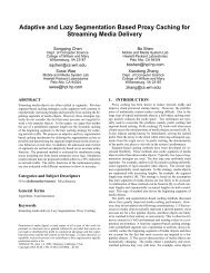
leads to some undesirable effects as shown <strong>in</strong> Figure 1, where more<br />
trees are visible along the horizon <strong>in</strong> the right image. Both images<br />
are generated from the same camera location. However, <strong>in</strong> the right<br />
image, the camera has been tilted downwards. While the cameraobject<br />
distance has not changed for these trees, the rotation of the<br />
camera has resulted <strong>in</strong> reduced Z values. This causes a reduction<br />
<strong>in</strong> the computed fog density, allow<strong>in</strong>g trees that were previously<br />
<strong>in</strong>visible, to become visible.<br />
Figure 2 shows how this artifact can occur <strong>us<strong>in</strong>g</strong> <strong>OpenGL</strong> fog<br />
model. The grey band shows the visible region from no fog to complete<br />
fog. In the left diagram, Tree 1 is <strong>in</strong> the fully fogged region.<br />
With the camera rotated <strong>in</strong> the right diagram, Tree 1 falls <strong>in</strong>to the<br />
partially fogged region, and thus become visible.<br />
Recent additions to the <strong>OpenGL</strong> standard <strong>in</strong>clude the ability to<br />
specify the effective ′ Z ′ value, or depth of a vertex for the purposes<br />
of fog computations. Often referred to as the fog extension, this<br />
permits significantly more control over the fog generation and allows<br />
effects such as height dependent fog, but at the expense of<br />
provid<strong>in</strong>g more per-vertex data - already a potential bottleneck, and<br />
more CPU cycles.<br />
∗ e-mail: a@aol.com<br />
Anonymous ∗<br />
A Research<br />
Figure 1: Problems with standard fog. The right image shows more<br />
trees on the hillside when the camera is tilted downwards.<br />
Figure 2: <strong>Fog</strong> artifacts<br />
Another problem with the fog model <strong>in</strong> <strong>OpenGL</strong> is that only<br />
rendered objects are fogged, leav<strong>in</strong>g the background unaffected, as<br />
shown by Figure 3.<br />
The obvious solution to this problem is to set the background<br />
color to the fog color, but this only works for homogeneous fog,<br />
not the fog extension, which usually requires a graded background.<br />
Thus, the standard fog model employed by <strong>OpenGL</strong> is somewhat<br />
limited <strong>in</strong> its application.<br />
Considerable work has been done to improve the situation <strong>us<strong>in</strong>g</strong><br />
either physically-based or appearance-based approaches [1] [2] [4]<br />
[5] [6] [8] [9] [10] [11] [12] [16] [18] [19] [21] [22] [23] [25], with<br />
the ultimate goal of simulat<strong>in</strong>g fully heterogeneous fog <strong>in</strong> three dimensions.<br />
However, most approaches either cannot achieve the performance<br />
characteristics required for real time applications, or require<br />
sophisticated algorithms that must be <strong>in</strong>tegrated <strong>in</strong>to the ma<strong>in</strong><br />
render<strong>in</strong>g pipel<strong>in</strong>e.<br />
In this paper we present a new method of generat<strong>in</strong>g real-time<br />
heterogeneous fog <strong>us<strong>in</strong>g</strong> post-<strong>process<strong>in</strong>g</strong> technique. Our algorithm<br />
uses analytical functions to evaluate the fog <strong>in</strong>tegral along the l<strong>in</strong>e<br />
of sight, accurately comput<strong>in</strong>g the fog density on a per-pixel basis to<br />
produce heterogeneous fog effects. It requires only the depth buffer<br />
generated dur<strong>in</strong>g the normal render<strong>in</strong>g process, mak<strong>in</strong>g it very easy<br />
to <strong>in</strong>tegrate <strong>in</strong>to exist<strong>in</strong>g render<strong>in</strong>g applications. Additionally, it is<br />
also extremely fast, be<strong>in</strong>g implemented entirely on the GPU.<br />
In the next section, we review the exist<strong>in</strong>g approaches for real<br />
time fog render<strong>in</strong>g. Section 3 describes the technical details <strong>in</strong>clud<strong>in</strong>g<br />
fog approximation <strong>in</strong> appearance based fog simulation and<br />
our new algorithm with hardware acceleration technique. Section<br />
4 presents the implementation as well as the <strong>in</strong>tegration of our al-
Figure 3: Background is not fogged<br />
gorithm to the <strong>OpenGL</strong> render<strong>in</strong>g pipel<strong>in</strong>e. Section 5 shows the<br />
results, section 6 compares our method with others and section 7<br />
discusses our conclusions and ideas for future work.<br />
2 PREVIOUS WORK<br />
Exist<strong>in</strong>g work for realistic fog render<strong>in</strong>g can be broadly categorized<br />
as physically-based and appearance-based.<br />
In the physically-based approach, fog is considered as a standard<br />
participat<strong>in</strong>g medium, and is generated through global illum<strong>in</strong>ation<br />
algorithms. To reduce expensive computational cost, simplifications<br />
are made through s<strong>in</strong>gle scatter<strong>in</strong>g and multiple scatter<strong>in</strong>g<br />
models. In s<strong>in</strong>gle scatter<strong>in</strong>g, the participat<strong>in</strong>g medium is assumed to<br />
be optically th<strong>in</strong>, allow<strong>in</strong>g the source radiance simplification to ignore<br />
multiple scatter<strong>in</strong>g with<strong>in</strong> the medium. Analytic method [23]<br />
has been used to solve the <strong>in</strong>tegral problem presented <strong>in</strong> the participat<strong>in</strong>g<br />
medium with significant simplification. The determ<strong>in</strong>istic<br />
method [11] [16] aims at numerical solutions of the same problem,<br />
for example, Zhu et al [25] applies ’depth peel<strong>in</strong>g’[7] technique to<br />
calculate volumetric light<strong>in</strong>g, while the stochastic method [22] is<br />
found to be used <strong>in</strong> clouds <strong>in</strong>stead of fog by apply<strong>in</strong>g random sampl<strong>in</strong>g<br />
to solve the equation for the radiance reach<strong>in</strong>g the eye for<br />
the s<strong>in</strong>gle scatter<strong>in</strong>g. In multiple scatter<strong>in</strong>g, both determ<strong>in</strong>istic and<br />
stochastic methods used here conta<strong>in</strong> two stages: an illum<strong>in</strong>ation<br />
pass for comput<strong>in</strong>g the source radiance, and a visualization pass for<br />
the f<strong>in</strong>al image. Some of the determ<strong>in</strong>istic methods [21] extend the<br />
classical radiosity method that accounts for isotropic emitt<strong>in</strong>g and<br />
scatter<strong>in</strong>g medium (zonal method), other improvements can deal<br />
with anisotropy <strong>us<strong>in</strong>g</strong> spherical harmonics [2] [10], discrete ord<strong>in</strong>ates,<br />
or implicit representation. Stochastic methods [6] [9] [12]<br />
[18] solve the transport equation by means of random sampl<strong>in</strong>g, <strong>us<strong>in</strong>g</strong><br />
random paths along iteration po<strong>in</strong>ts. In summary, while these<br />
methods can produce realistic scenes, they come with a high computational<br />
cost, even when hardware acceleration is implemented,<br />
they are not real-time. Cerezo et al [5] provides a comprehensive<br />
review of the participat<strong>in</strong>g medium render<strong>in</strong>g techniques.<br />
In appearance based approaches, the idea is to produce visually<br />
pleasant results without expensive global illum<strong>in</strong>ation determ<strong>in</strong>ation.<br />
Perl<strong>in</strong> [19] documented snapshots of thoughts such as <strong>us<strong>in</strong>g</strong><br />
Gabor functions for simulat<strong>in</strong>g atmospheric effects. Biri et al [3]<br />
[13] suggested model<strong>in</strong>g of complex fog through a set of functions<br />
allow<strong>in</strong>g analytical <strong>in</strong>tegration. Zdrojewska [26] <strong>in</strong>troduced<br />
randomness <strong>in</strong> attenuation through perl<strong>in</strong> noise and produces heterogeneous<br />
look<strong>in</strong>g fog without l<strong>in</strong>e of sight <strong>in</strong>tegral. Height dependent,<br />
or layered fog, varies the fog density based on the height<br />
[8] [14]([19] dose not conta<strong>in</strong> implementation details). Mech [15]<br />
proposed to represent the gas boundary by a polygonal surface, <strong>us<strong>in</strong>g</strong><br />
graphics hardware to determ<strong>in</strong>e the attenuation factor for each<br />
pixel <strong>in</strong>side or beh<strong>in</strong>d the gas. Nvidia developers[17] adopted similar<br />
idea proposed <strong>in</strong> [15], developed a RGB-encod<strong>in</strong>g technique<br />
comb<strong>in</strong><strong>in</strong>g with ’depth peel<strong>in</strong>g’[7] to render fog polygon objects<br />
as thick volumes on GPU. The advantage of these approaches is<br />
that they allow simple but fast render<strong>in</strong>g of fog. However, Biri’s<br />
method is not yet fast enough on current hardware, and Zdrojewska’s<br />
method does not take fog volume <strong>in</strong>to account, ca<strong>us<strong>in</strong>g</strong> <strong>in</strong>correct<br />
results when consider<strong>in</strong>g motion parallax, mak<strong>in</strong>g it more<br />
suited to simulate low cloud <strong>in</strong> natural environments without travel<strong>in</strong>g<br />
through the fog (i.e. as opposed to man-made environments).<br />
Although Biri’s algorithm used analytical functions to approximate<br />
the ext<strong>in</strong>ction coefficient, the performance of the implementation<br />
was constra<strong>in</strong>ed by the way <strong>in</strong> which the depth <strong>in</strong>formation was<br />
used for <strong>in</strong>tegration, and the pixel texture technique used <strong>in</strong> [8]<br />
did not produce real-time results. <strong>Fog</strong> polygon volume based approach<br />
[15] [17] suite more for small volumes such as light shaft,<br />
smoke, etc. An additional constra<strong>in</strong>t imposed by many of these<br />
techniques is that the production of the fog effect must be <strong>in</strong>tegrated<br />
<strong>in</strong>to the ma<strong>in</strong> render<strong>in</strong>g pipel<strong>in</strong>e - someth<strong>in</strong>g that is not practical for<br />
many exist<strong>in</strong>g render<strong>in</strong>g applications. Our new appearance-based<br />
approach avoids this constra<strong>in</strong>t by <strong>us<strong>in</strong>g</strong> the depth buffer to reconstruct<br />
scene depth <strong>in</strong>formation, while perform<strong>in</strong>g l<strong>in</strong>e-of-sight <strong>in</strong>tegration<br />
on the GPU <strong>us<strong>in</strong>g</strong> analytical functions and true Euclidean<br />
distance.<br />
3 TECHNICAL DETAILS<br />
To compute fog color, we need to <strong>in</strong>tegrate along the ray between<br />
the camera position and the fragment position given the fog density<br />
function. There are two ma<strong>in</strong> aspects to generat<strong>in</strong>g fog <strong>us<strong>in</strong>g</strong> a post<br />
<strong>process<strong>in</strong>g</strong> approach. The first is to reconstruct the 3D position of<br />
each fragment <strong>in</strong> the frame buffer, while the second is to compute<br />
the fog based on the fragment and eye positions.<br />
3.1 3D Fragment Position Reconstruction<br />
In order to evaluate the fog <strong>in</strong>tegral along l<strong>in</strong>e of sight accurately,<br />
the 3D position of each fragment <strong>in</strong> world coord<strong>in</strong>ate needs to be<br />
reconstructed. The depth buffer stores transformed depth value for<br />
each fragment and can be used to reconstruct 3D fragment position.<br />
Generally, most post <strong>process<strong>in</strong>g</strong> applications that need depth <strong>in</strong>formation<br />
use specialized shaders and alternate render targets to ’lay<br />
down’ depth <strong>in</strong>formation <strong>in</strong> a form which can readily be used <strong>in</strong> the<br />
post <strong>process<strong>in</strong>g</strong> stages. The disadvantage to this approach is that it<br />
requires significantly more <strong>in</strong>tegration <strong>in</strong>to the render<strong>in</strong>g application.<br />
It can also impact performance (requir<strong>in</strong>g an extra scene render<strong>in</strong>g<br />
pass) and bandwidth (requir<strong>in</strong>g an extra render target). For<br />
our new approach, we use a standard post-<strong>process<strong>in</strong>g</strong> technique of<br />
draw<strong>in</strong>g a screen aligned polygon with customized vertex/fragment<br />
shaders, but use the regular depth buffer generated as part of the normal<br />
render<strong>in</strong>g process as an <strong>in</strong>put texture <strong>in</strong>stead. The problem with<br />
the depth buffer is that the depth <strong>in</strong>formation is non-l<strong>in</strong>ear, hav<strong>in</strong>g<br />
been transformed by the modelview and projection matrices. The<br />
first step is to reconstruct scene depth. A naive approach to this is<br />
to use an <strong>in</strong>verted modelview/projection matrix, along with normalized<br />
x and y values, to compute the full 3D fragment position relative<br />
to the camera. Once this is known, along with the position and<br />
orientation of the camera, the real world position of the fragment<br />
can be obta<strong>in</strong>ed. However, this turns out to be quite expensive, so<br />
we use an alternative, faster approach. The first step is to compute<br />
the depth value z. From an exam<strong>in</strong>ation of the projection matrix,<br />
we can deduce that<br />
where<br />
z = −P34<br />
z ′<br />
w ′ + P33<br />
P33 =<br />
f + n<br />
n − f<br />
(1)<br />
(2)
Figure 4: Reconstruct 3D fragment position, relative to the camera.<br />
and<br />
P34 =<br />
−2 f × n<br />
f − n<br />
where n is the distance to the near clipp<strong>in</strong>g plane, and f is the distance<br />
to the far clipp<strong>in</strong>g plane.<br />
Given that we can obta<strong>in</strong> z′<br />
w ′ from the depth buffer, and both P33<br />
and P34 can either be computed based on knowledge of the camera<br />
properties, or obta<strong>in</strong>ed directly from the projection matrix, we can<br />
easily convert a value from the depth buffer to an actual depth value.<br />
This also has the result of reduc<strong>in</strong>g it to a scalar operation, requir<strong>in</strong>g<br />
one addition and one division per pixel.<br />
The second step is to compute the real world position of the fragment<br />
based on this depth value, relative to the camera. To do this,<br />
we take advantage of the graphics hardware by sett<strong>in</strong>g up a unit<br />
vector <strong>in</strong> the direction of the fragment, <strong>us<strong>in</strong>g</strong> a vertex shader <strong>in</strong> the<br />
post <strong>process<strong>in</strong>g</strong>. The hardware automatically <strong>in</strong>terpolates this for us<br />
to use <strong>in</strong> the fragment shader, where it is used to generate the relative<br />
location of the fragment by comput<strong>in</strong>g the fragment Euclidean<br />
distance |U|.<br />
|U| = z<br />
(4)<br />
û · ˆv<br />
where û is the unit vector <strong>in</strong> the direction of the camera to the fragment,<br />
ˆv is the unit vector <strong>in</strong> the direction of the camera, and z is<br />
def<strong>in</strong>ed <strong>in</strong> (1). Figure 4 shows 3D fragment position reconstruction.<br />
The 3D position of the fragment relative to the camera is then<br />
obta<strong>in</strong>ed by<br />
U = |U| · û<br />
The f<strong>in</strong>al step is to add the position of the camera to U, produc<strong>in</strong>g<br />
the real world 3D position of the fragment P, where P =<br />
(x f ragment,yfragment,zfragment).<br />
3.2 <strong>Fog</strong> Computation<br />
3.2.1 Homogeneous <strong>Fog</strong><br />
Appearance-based fog generally assumes the scatter<strong>in</strong>g of a<br />
constant ambient illum<strong>in</strong>ation <strong>in</strong> a homogeneous non-emitt<strong>in</strong>g<br />
medium. It simplifies the transport equation <strong>in</strong> participat<strong>in</strong>g<br />
medium model as follows:<br />
L(x) = e κa|x0−x| L(x0) + (1 − e κa|x0−x| )Le<br />
where Le represents the constant amount of light, L(x0) is the radiance<br />
of light at space po<strong>in</strong>t x0, and κa be<strong>in</strong>g a constant as the<br />
absorption coefficient to represent homogeneous medium.<br />
The first term characterizes the loss of light of the object surface<br />
due to the absorption of the medium. The second term describes the<br />
contribution of the scatter<strong>in</strong>g with<strong>in</strong> the medium. The <strong>OpenGL</strong> fog<br />
(3)<br />
(5)<br />
model uses this approximation to <strong>in</strong>tegrate a uniform attenuation<br />
due to medium absorption between the object and the viewer.<br />
C = f ·C<strong>in</strong> + (1 − f ) ·Cf og<br />
where f = e −(density·z) , z is the eye-coord<strong>in</strong>ate distance between the<br />
viewpo<strong>in</strong>t and the fragment, C<strong>in</strong> is the fragment color, C f og is the<br />
fog color. C<strong>in</strong> maps to L(x0), Cf og maps to Le.<br />
3.2.2 Layered <strong>Fog</strong><br />
Layered fog extends equation (5) to non-uniform attenuation of the<br />
medium - f (u), based on height variation.<br />
L(x) = e − f ragment<br />
camera<br />
f (u)du L(x0) + (1 − e − f ragment<br />
camera<br />
f (u)du )Le<br />
Once we have the fragment position <strong>in</strong> real world coord<strong>in</strong>ates, we<br />
can compute the expected blend<strong>in</strong>g of the fragment color with the<br />
fog color, based on the amount of fog between the camera and the<br />
fragment. To do this, we need to evaluate the fog density <strong>in</strong>tegral<br />
along the camera-to-fragment vector. In the case of a homogeneous<br />
fog, this computation is trivial, while <strong>in</strong> the case of fully heterogeneous<br />
fog, it can be computationally very expensive. Layered fog,<br />
where the fog density f , is dependent only on the height y, is a special<br />
case of heterogeneous fog. Suppose the total fog between the<br />
camera, and the fragment position, is given by the <strong>in</strong>tegral F along<br />
the camera-fragment vector.<br />
f ragment<br />
F = f (u)du<br />
camera<br />
where f (u) is the fog density at a 3d space position. S<strong>in</strong>ce the fog<br />
density is only dependent upon y, this can be simplified:<br />
<br />
1 y f ragment<br />
F =<br />
f (y)dy (6)<br />
s<strong>in</strong>(θ f ragment)<br />
ycamera<br />
where θ f ragment is the angle of <strong>in</strong>cl<strong>in</strong>ation of the camera to fragment<br />
vector, calculated on per pixel basis, ycamera is the y coord<strong>in</strong>ate<br />
of the eye po<strong>in</strong>t <strong>in</strong> world space, and y f ragment is the fragment<br />
y position <strong>in</strong> world coord<strong>in</strong>ate. Figure 5 shows the geometric<br />
relationships among Euclidean distance |U|, θ and the height<br />
|y f ragment − ycamera|. We can easily apply |U| to express equation<br />
(6) as follows:<br />
F =<br />
<br />
|U|<br />
y f ragment<br />
f (y)dy (7)<br />
|y f ragment − ycamera| ycamera<br />
Obviously, equation (7) coverts absorption of a ray along l<strong>in</strong>e of<br />
Figure 5: Height Dependent <strong>Fog</strong> Computation Per Fragment<br />
sight to its vertical component by a scal<strong>in</strong>g factor.<br />
equation(4), we def<strong>in</strong>e layered fog as below:<br />
Comb<strong>in</strong><strong>in</strong>g<br />
F = z<br />
û · ˆv ·<br />
<br />
1<br />
y f ragment<br />
f (y)dy<br />
|y f ragment − ycamera|<br />
(8)<br />
ycamera
The method of evaluat<strong>in</strong>g this <strong>in</strong>tegral depends on the fog function.<br />
Functions that can be <strong>in</strong>tegrated analytically are generally trivial<br />
to compute <strong>in</strong> a fragment shader, but it can be difficult to achieve<br />
realistic look<strong>in</strong>g s<strong>in</strong>ce most analytical functions produce periodic<br />
patterns unless a large number of terms are used, and this can be<br />
slow to evaluate. Hard coded functions can be used to produce customized<br />
fog patterns, well suited to layered fog. Non-analytical<br />
functions present the biggest problem, s<strong>in</strong>ce approximation methods<br />
require loop<strong>in</strong>g that seriously degrades performance. Our solution<br />
to this was to pre-compute the fog <strong>in</strong>tegral across its expected<br />
range, stor<strong>in</strong>g the result <strong>in</strong> a texture that could be used as a lookup<br />
table <strong>in</strong> the fragment shader.<br />
3.2.3 Heterogeneous <strong>Fog</strong><br />
By <strong>us<strong>in</strong>g</strong> a fog density function that is <strong>in</strong>dependent <strong>in</strong> each dimension,<br />
we can easily extend our method to produce 3 dimensional<br />
heterogeneous fog effects. In this case, the fog <strong>in</strong>tegral F can be<br />
modeled as follows:<br />
F(x,y,z) = F(x)F(y)F(z)<br />
As with layered fog, functions that can be <strong>in</strong>tegrated analytically<br />
can be evaluated directly <strong>in</strong> the fragment shader, or the <strong>in</strong>tegrals<br />
can be pre-computed and stored <strong>in</strong> textures.<br />
3.2.4 Putt<strong>in</strong>g it Together<br />
Once the fog <strong>in</strong>tegral has been evaluated, the fragment can be<br />
blended with the fog color. We choose an exponential blend<strong>in</strong>g<br />
function<br />
f = e −F<br />
although any suitable function can be used.<br />
3.2.5 Color Gradient <strong>Fog</strong><br />
We can extend this algorithm to evaluate fog <strong>in</strong>tegrals on <strong>in</strong>dividual<br />
color components <strong>us<strong>in</strong>g</strong> different fog density functions. This can<br />
be used to produce color variations <strong>in</strong> fog, for example, simulat<strong>in</strong>g<br />
smog when certa<strong>in</strong> colors are scattered or absorbed more than<br />
others. Us<strong>in</strong>g layered fog as an example, the fog computation is<br />
modeled by the follow<strong>in</strong>g:<br />
Fr||g||b = z<br />
û · ˆv ·<br />
<br />
1<br />
y f ragment<br />
f<br />
|y f ragment − ycamera|<br />
r||g||b(y)dy (9)<br />
ycamera<br />
where f r||g||b(y) is fog density function for r, g or b color component.<br />
The fragment is then blended <strong>us<strong>in</strong>g</strong> the <strong>in</strong>dividually computed<br />
component values as follows;<br />
(Sr + 1 − Dr,Sg + 1 − Dg,Sb + 1 − Db)<br />
where (Sr,Sg,Sb,Sa) and (Dr,Dg,Db,Da) are the source and dest<strong>in</strong>ation<br />
blend<strong>in</strong>g factors respectively.<br />
4 IMPLEMENTATION<br />
Our implementation is based upon a custom hierarchical scene<br />
management and <strong>OpenGL</strong> based render<strong>in</strong>g eng<strong>in</strong>e developed by the<br />
authors, although any <strong>OpenGL</strong> based render<strong>in</strong>g eng<strong>in</strong>e should be<br />
suitable. Written <strong>in</strong> C++, our application provides ’hooks’ <strong>in</strong>to various<br />
parts of the render<strong>in</strong>g pipel<strong>in</strong>e, allow<strong>in</strong>g us to easily <strong>in</strong>sert our<br />
post <strong>process<strong>in</strong>g</strong> algorithm.<br />
The first step is to render the scene <strong>in</strong>to the frame buffer, which<br />
is done by the application as before. Once the scene render<strong>in</strong>g is<br />
complete, the scene post <strong>process<strong>in</strong>g</strong> is triggered just prior to the<br />
frame buffer swap. At this po<strong>in</strong>t, the depth buffer is captured <strong>us<strong>in</strong>g</strong><br />
the <strong>OpenGL</strong> copy-to-texture functionality. Next, the depth conversion<br />
parameters P33(equation(2)) and P34(equation(3)) are computed<br />
based on the camera properties. The post <strong>process<strong>in</strong>g</strong> is then<br />
<strong>in</strong>itiated by draw<strong>in</strong>g a screen-aligned polygon, textured with the<br />
depth texture, and <strong>us<strong>in</strong>g</strong> custom vertex and fragment shaders written<br />
<strong>in</strong> the <strong>OpenGL</strong> Shad<strong>in</strong>g Language. The vertex shader is used to<br />
set up the eye-to-fragment unit vector, def<strong>in</strong>ed <strong>in</strong> real world coord<strong>in</strong>ates.<br />
This is <strong>in</strong>terpolated by the hardware pipel<strong>in</strong>e, and delivered<br />
to the fragment shader for use <strong>in</strong> comput<strong>in</strong>g the fragment position.<br />
The depth conversion parameters needed for convert<strong>in</strong>g the depth<br />
buffer values are passed to the fragment shader as uniform variables.<br />
Figure 6 shows the steps <strong>in</strong> our post <strong>process<strong>in</strong>g</strong> implementation,<br />
and how it <strong>in</strong>tegrates <strong>in</strong>to the render<strong>in</strong>g application.<br />
Figure 6: Integration of <strong>Post</strong>-<strong>process<strong>in</strong>g</strong><br />
To blend the fog color with the fragment color, we take advantage<br />
of the standard <strong>OpenGL</strong> blend<strong>in</strong>g functionality and simply<br />
compute an alpha value <strong>in</strong> the fragment shader. The output from<br />
the fragment shader is a fragment color consist<strong>in</strong>g of the RGB fog<br />
color, and the computed alpha (fog) value. The render<strong>in</strong>g pipel<strong>in</strong>e<br />
takes care of the rest of the work by blend<strong>in</strong>g the fog color with the<br />
exist<strong>in</strong>g fragment <strong>in</strong> the frame-buffer.<br />
The fragment shader itself is relatively simple. Pseudo code for<br />
generat<strong>in</strong>g layered fog is given for it below.<br />
read fragment depth from depth texture<br />
perform scene depth reconstruction<br />
compute eye-to-fragment vector<br />
compute fragment position <strong>in</strong> real world<br />
compute Euclidean distance between the<br />
camera and the fragment<br />
evaluate fog <strong>in</strong>tegral<br />
compute alpha value<br />
5 RESULTS<br />
The algorithms <strong>in</strong> this paper were implemented on a 2.8GHz Pentium<br />
IV platform, with 1GB RAM and an nVIDIA 6800 graphics<br />
card, runn<strong>in</strong>g L<strong>in</strong>ux.<br />
A number of test scenes were chosen <strong>us<strong>in</strong>g</strong> a variety of resolutions<br />
and fog functions.<br />
The first test scene Figure 7, uses a simple four po<strong>in</strong>t ramp function<br />
to produce a simple height dependent (layered) fog. The idea<br />
beh<strong>in</strong>d this fog function was to produce a th<strong>in</strong> layer of fog, just<br />
above the ground.<br />
Figure 8 is an underwater scene that demonstrates another use of<br />
fog. This scene uses a fog density that <strong>in</strong>creases l<strong>in</strong>early with depth<br />
to simulate the <strong>in</strong>creas<strong>in</strong>g attenuation of light <strong>in</strong> water.<br />
Figure 9, the cave scene, uses a two po<strong>in</strong>t fog function, with a<br />
uniform density up to a height y1, then fall<strong>in</strong>g l<strong>in</strong>early to zero at a<br />
po<strong>in</strong>t y2.
Figure 7: Serene Street - A low level ground fog <strong>us<strong>in</strong>g</strong> a simple height<br />
based function<br />
Figure 10, another cave scene, with heterogeneous fog based on<br />
Perl<strong>in</strong> noise functions (pre-<strong>in</strong>tegrated) for X and Z, and an exponential<br />
function for the height.<br />
Figure 11, the Village scene, uses heterogeneous fog based on 3<br />
Perl<strong>in</strong> noise functions.<br />
Figure 12 shows a selection of scenes that use a simple fog density<br />
function that <strong>in</strong>creases l<strong>in</strong>early with decreas<strong>in</strong>g height. The<br />
heterogeneous appearance is a result of depressions <strong>in</strong> the terra<strong>in</strong>,<br />
and significantly improves the perception of depth.<br />
Tests <strong>in</strong>dicated that the cost of generat<strong>in</strong>g layered fog effect<br />
ranges between 0.39 to 3.08 milliseconds for the above scenes, depend<strong>in</strong>g<br />
on the screen resolution and complexity of the fog function.<br />
The maximum screen resolution was 1024 × 1024.<br />
6 DISCUSSION<br />
S<strong>in</strong>ce our technique is post-<strong>process<strong>in</strong>g</strong>, and evaluates the fog <strong>in</strong>tegral<br />
along the l<strong>in</strong>e of sight on per pixel basis, it does not suffer<br />
from the popp<strong>in</strong>g effect discussed <strong>in</strong> figure 2, nor the background<br />
problem shown <strong>in</strong> figure 3. It elim<strong>in</strong>ates limitations <strong>in</strong> methods<br />
such as Biri’s [3], which produces noticeable artifacts for fog render<strong>in</strong>g<br />
when the texture size is small compared to the image size, or<br />
compromised performance if a larger texture is used. To enhance<br />
the heterogeneous appearance of the fog render<strong>in</strong>g, we apply Perl<strong>in</strong><br />
noise functions <strong>in</strong>stead of equipotential functions used for local<br />
ref<strong>in</strong>ement by Biri et al. Our method can also easily simulate the<br />
effects of w<strong>in</strong>d to animate the fog by provid<strong>in</strong>g time dependent offsets<br />
when evaluat<strong>in</strong>g the fog <strong>in</strong>tegrals.<br />
7 CONCLUSION AND FUTURE WORK<br />
In this paper we demonstrate a new, flexible and efficient method<br />
of generat<strong>in</strong>g advanced fog effects <strong>in</strong> real time. We apply post<strong>process<strong>in</strong>g</strong><br />
techniques <strong>in</strong> the GPU to produce natural look<strong>in</strong>g heterogeneous<br />
fog <strong>us<strong>in</strong>g</strong> Euclidean fragment distance reconstructed<br />
from the depth buffer. S<strong>in</strong>ce the implementation requires only the<br />
normal depth buffer as <strong>in</strong>put, we avoid the need for customized<br />
shaders <strong>in</strong> the standard render<strong>in</strong>g pipel<strong>in</strong>e, mak<strong>in</strong>g it very easy to<br />
<strong>in</strong>tegrate <strong>in</strong>to exist<strong>in</strong>g render<strong>in</strong>g applications. In summary, our contribution<br />
<strong>in</strong>cludes the follow<strong>in</strong>g attributes:<br />
• Accurate scene depth reconstruction from the depth buffer.<br />
Figure 8: Underwater Adventure<br />
• Accurate 3D fragment position reconstruction <strong>in</strong> world space<br />
from scene depth.<br />
• An easily <strong>in</strong>tegrated GPU based post-<strong>process<strong>in</strong>g</strong> technique for<br />
real time frame rates.<br />
• <strong>Real</strong>istic Heterogeneous fog and extension of color gradient<br />
fog.<br />
Our method makes the assumption of <strong>in</strong>dependent fog density on<br />
three dimensions. In future work, we need to solve arbitrary fog<br />
density <strong>in</strong>tegral problem <strong>in</strong>clud<strong>in</strong>g correlations across dimensions,<br />
and extend this technique <strong>in</strong>to a global illum<strong>in</strong>ation model.<br />
REFERENCES<br />
[1] N. Adabala and S. Manohar. Model<strong>in</strong>g and render<strong>in</strong>g of gaseous phenomena<br />
<strong>us<strong>in</strong>g</strong> particle maps. Journal of Visualization and Computer<br />
Animation, 11(5):279–294, 2000.<br />
[2] N. Bhate and A. Tokuta. Volume render<strong>in</strong>g of media with directional<br />
scatter<strong>in</strong>g. In Third Eurographics Workshop on Render<strong>in</strong>g, pages 227–<br />
245, May 1992.<br />
[3] V. Biri, S. Michel<strong>in</strong>, and D. Arques. <strong>Real</strong>-time animation of realistic<br />
fog. In Render<strong>in</strong>g Techniques 2002 (Proceed<strong>in</strong>gs of the Thirteenth<br />
Eurographics Workshop on Reder<strong>in</strong>g), June 2002.<br />
[4] P. Blasi, B. L. Saec, and C. Schlick. An importance driven monte-carlo<br />
solution to the global illum<strong>in</strong>ation problem. In Fifth Eurographics<br />
Workshop Render, pages 173–183, June 1994.<br />
[5] E. Cerezo, F. Perez, X. Pueyo, F. Seron, and F. X. Sillionn. A survey<br />
on participat<strong>in</strong>g media render<strong>in</strong>g technique. The Visual Computer,<br />
21(5):303–328, 2005.<br />
[6] E. Dumont. Semi-monte carlo light trac<strong>in</strong>g applied to the study of<br />
road visibility <strong>in</strong> fog. In Proceed<strong>in</strong>gs of the Third International Conference<br />
on Monte Carlo and Quasi Monte Carlo Methods <strong>in</strong> Scientific<br />
Comput<strong>in</strong>g, 1998.<br />
[7] C. Everitt. Interactive order-<strong>in</strong>dependent transparency.<br />
http://developer.nvidia.com/attach/6545, 2001.<br />
[8] W. Heidich, R. Westermann, H. Seidel, and T. Ertl. Applications of<br />
pixel textures <strong>in</strong> visualication and realistic image synthesis. In Proc.<br />
ACM Sym. On Interactive 3D Grahpics, pages 127–134, April 1999.<br />
[9] H. W. Jensen and P. H. Christensen. Efficient simulation of light transport<br />
<strong>in</strong> scenes with participat<strong>in</strong>g media <strong>us<strong>in</strong>g</strong> photon maps. In Computer<br />
Graphics (ACM SIGGRAPH 98 Proceed<strong>in</strong>gs), pages 311–320,<br />
1998.
Figure 9: Mystic Cave - Layered <strong>Fog</strong> <strong>us<strong>in</strong>g</strong> a simple two po<strong>in</strong>t ramp<br />
function<br />
Figure 10: Mystic Cave - Heterogeneous <strong>Fog</strong> based on Perl<strong>in</strong> noise<br />
functions <strong>in</strong> 2 dimensions, and a height based exponential function<br />
Figure 11: Barnyard Breeze - Heterogeneous fog <strong>us<strong>in</strong>g</strong> Perl<strong>in</strong> noise<br />
functions <strong>in</strong> 3 dimensions<br />
Figure 12: Great Wall Morn<strong>in</strong>g Mist - Layered fog exaggerates the<br />
terra<strong>in</strong> features
[10] J. T. Kajiya and B. P. V. Herzen. Ray trac<strong>in</strong>g volume densities. In<br />
Computer Graphics (ACM SIGGRAPH 84 Proceed<strong>in</strong>gs), volume 18,<br />
pages 165–174, July 1984.<br />
[11] R. Klassen. Model<strong>in</strong>g the effect of the atmosphere on light. ACM<br />
Transactions on Graphics, 6(3):215–237, 1987.<br />
[12] E. P. Lafortune and Y. D. Willems. Render<strong>in</strong>g participat<strong>in</strong>g media with<br />
bidirectional path trac<strong>in</strong>g. In Render<strong>in</strong>g Techniques96 (Proceed<strong>in</strong>gs<br />
of the Seventh Eurographics Workshop on Render<strong>in</strong>g), pages 91–100.<br />
Spr<strong>in</strong>ger-Verlag/Wien, 1996.<br />
[13] P. Lecocq, S. Michel<strong>in</strong>, D. Arques, and A. Kemeny. Mathematical<br />
approximation for real-time render<strong>in</strong>g of participat<strong>in</strong>g media. In Proceed<strong>in</strong>g<br />
of Eighth Pacific Conference on Computer Graphics and Applications,<br />
page 400, 2000.<br />
[14] J. Legakis. Fast muilti-layer fog. In Siggraph’98 Conference Abstracts<br />
and Applications, page 266, 1998.<br />
[15] R. Mech. Hardware-accelerated real-time render<strong>in</strong>g of gaseous phenomena.<br />
Journal of Graphics Tools, 6(3):1–16, 2001.<br />
[16] T. Nishita, Y. Miyawaki, and E. Nakamae. A shad<strong>in</strong>g model for atmospheric<br />
scatter<strong>in</strong>g consider<strong>in</strong>g lum<strong>in</strong>ous <strong>in</strong>tensity distribution of light<br />
sources. In Computer Graphics (ACM SIGGRAPH’87 Proceed<strong>in</strong>gs),<br />
volume 21, pages 303–310, 1987.<br />
[17] Nvidia. <strong>Fog</strong> polygon volumes-render<strong>in</strong>g objects as thick volumes.<br />
http://download.developer.nvidia.com/developer/SDK/<br />
<strong>in</strong>dividual Samples/DEMOS/Direct3D9/src/ <strong>Fog</strong>PolygonVolumes3/docs/<strong>Fog</strong>PolygonVolumes3.pdf,<br />
2004.<br />
[18] S. N. Pattanaik and S. P. Mudur. Computation of global illum<strong>in</strong>ation <strong>in</strong><br />
a participat<strong>in</strong>g medium by monte carlo simulation. The Journal of Visualization<br />
and Computer Animation, 4(3):133–152, July-September<br />
1993.<br />
[19] K. Perl<strong>in</strong>. Us<strong>in</strong>g gabor functions to make atmosphere <strong>in</strong> computer<br />
graphics. http://mrl.nyu.edu/ perl<strong>in</strong>/experiments/garbor/, Year unknown.<br />
[20] R. J. Rost. <strong>OpenGL</strong> Shad<strong>in</strong>g Language, 2nd Edition. Addison Wesley,<br />
2006.<br />
[21] H. E. Rushmeier and K. E. Torrance. The zonal method for calculat<strong>in</strong>g<br />
light <strong>in</strong>tensities <strong>in</strong> the presence of a participat<strong>in</strong>g medium. In Computer<br />
Graphics(ACM SIGGRAPH’87 Proceed<strong>in</strong>gs), pages 293–302,<br />
July 1987.<br />
[22] G. Sakas. dfast render<strong>in</strong>g of arbitrary distributed volume densities. In<br />
Eurographics’90, pages 519–530, July 1990.<br />
[23] P. J. Willis. Visual simulation of atmospheric haze. Computer Graphics<br />
Forum, 6(1):35–42, 1987.<br />
[24] M. Woo, J. Neider, and T. Davis. <strong>OpenGL</strong> Programm<strong>in</strong>g Guide, 5th<br />
Edition. Addison Wesley, 2005.<br />
[25] F. L. Y. Zhu, G.S. Owen and A. Aquillio. Gpu-based volumetric light<strong>in</strong>g<br />
simulation. In Computer Graphics and Imag<strong>in</strong>g, pages 160–162,<br />
August 2004.<br />
[26] D. Zdrojewska. <strong>Real</strong> time render<strong>in</strong>g of heterogenous fog based on<br />
the graphics hardware acceleration. http://www.cescg.org/CESCG-<br />
2004/web/Zdrojewska-Dorota/, 2004.