L33-L38 Nios II Interrupts without LQuiz - Courses
L33-L38 Nios II Interrupts without LQuiz - Courses
L33-L38 Nios II Interrupts without LQuiz - Courses

You also want an ePaper? Increase the reach of your titles
YUMPU automatically turns print PDFs into web optimized ePapers that Google loves.
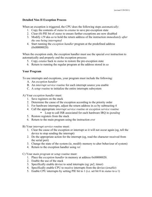
Detailed <strong>Nios</strong> <strong>II</strong> Exception Process<br />
(revised 3/28/2011)<br />
When an exception is triggered, the CPU does the following steps automatically:<br />
1. Copy the contents of status to estatus to save pre-exception state<br />
2. Clear (0) PIE bit of status to ensure further exceptions are now disabled<br />
3. Modify r29 aka ea to hold the return address of the instruction immediately after<br />
the one being interrupted<br />
4. Start running the exception handler program at the predefined address<br />
(0x00000020)<br />
When the exception ends, the exception handler must use the special eret instruction to<br />
automatically and properly end the exception process:<br />
5. Copy estatus back to status to restore the pre-exception state<br />
6. Return to running the regular program at the address stored in ea<br />
Your Program<br />
To use interrupts and exceptions, your program must include the following:<br />
A. An exception handler<br />
B. An interrupt service routine for each interrupt source you enable<br />
C. A setup routine to initialize the entire interrupts subsystem<br />
A) Your exception handler must:<br />
1. Save registers on the stack<br />
2. Determine the cause of the exception according to the priority order<br />
3. For hardware interrupts, adjust the return address in ea by subtracting 4<br />
4. Call the appropriate interrupt service routine or exception service routine<br />
• Loop to call ISR associated for each hardware IRQ in ipending<br />
5. Restore registers from the stack<br />
6. Return to the main program using the instruction eret<br />
B) Your interrupt service routine must:<br />
1. Clear the cause of the exception or interrupt so it will not occur again (eg, tell the<br />
device to stop sending the interrupt)<br />
2. Do the appropriate action for the interrupt (eg, read the character received from<br />
the serial port)<br />
3. Change the state of the system (ie, modify memory to alter behaviour of system)<br />
4. Return to the exception handler using ret<br />
C) Your main program or setup routine must:<br />
1. Place the exception handler in memory at address 0x00000020.<br />
2. Enable the use of the stack<br />
3. Specifically enable device to send interrupts (eg: ps2, timer)<br />
4. Specifically enable CPU to receive interrupts from the device (ienable)<br />
5. Enable CPU interrupts by setting PIE bit to 1 (i.e. set bit 0 in status to a 1)
Example: Count every 100ms on LEDG; no communication with main program.<br />
.include "ubc-de1media-macros.s"<br />
/*****************************************************************************<br />
* RESET SECTION<br />
* The <strong>Nios</strong> <strong>II</strong> assembler/linker places this section at address 0x00000000.<br />
* It must be
(revised 3/28/2011)<br />
/*****************************************************************************<br />
* TEXT SECTION<br />
* The <strong>Nios</strong> <strong>II</strong> assembler/linker should put the .text section after the .exceptions.<br />
* You may need to configure the Altera Monitor Program to locate it at address 0x400.<br />
*/<br />
.text<br />
.global _start<br />
_start:<br />
movia r23, IOBASE<br />
movia sp, STACK_END /* make sure stack is initialized */<br />
movia r4, interrupt_counts<br />
stw r0, 0(r4)<br />
movia r4, 100*50000 /* # of timer cycles in 100ms */<br />
call setup_timer_interrupts<br />
call setup_cpu_interrupts<br />
loop: ldwio r8, SWITCH(r23)<br />
stwio r8, LEDR(r23)<br />
br loop<br />
timer_isr:<br />
/* every interval, increment 'interrupt_counts' and display on LEDG */<br />
/* clear source of interrupt by writing 0 to TO bit */<br />
stwio r0, TIMER_STATUS(r23)<br />
/* process the interrupt, change state of system */<br />
movia r9, interrupt_counts<br />
ldw r8, 0(r9)<br />
addi r8, r8, 1<br />
stw r8, 0(r9)<br />
stwio r8, LEDG(r23) /* show count on LEDG */<br />
/* return from ISR */<br />
ret<br />
setup_timer_interrupts:<br />
/* set up timer to send interrupts */<br />
/* parameter r4 holds the # cycles for the timer interval */<br />
/* set the timer period */<br />
andi r2, r4, 0xffff /* extract low halfword */<br />
stwio r2, TIMER_START_LOW(r23)<br />
srli r2, r4, 16 /* extract high halfword */<br />
stwio r2, TIMER_START_HIGH(r23)<br />
/* start timer (bit2), count continuously (bit1), enable irq (bit0) */<br />
movi r2, 0b0111<br />
stwio r2, TIMER_CONTROL(r23)<br />
ret<br />
setup_cpu_interrupts:<br />
/* set up CPU to receive interrupts from timer */<br />
movi r2, 0x01 /* bit0 = irq0 = countdown timer device */<br />
wrctl ienable, r2<br />
movi r2, 1 /* bit0 = PIE */<br />
wrctl status, r2<br />
ret /* first instr. that may be interrupted */<br />
.data<br />
interrupt_counts:<br />
.word 0<br />
.end
Communication between ISR and Regular Program<br />
(revised 3/28/2011)<br />
One of the most difficult things to get correct is the communication between your ISR<br />
and the regular part of your program. There are two basic methods of communicating:<br />
1) By modifying specific registers<br />
2) By modifying memory<br />
Using registers is easiest, but it is really a shortcut and there are still some hidden<br />
difficulties. Using memory is the proper method, and the only way available from C<br />
language. However, it was already discussed earlier and will not be repeated here.<br />
To use registers for communication, you must use assembly language. You must<br />
decide ahead of time which specific register will be dedicated for the communication.<br />
The communicating register must not be saved/restored by the exception handler.<br />
In the second example assembly program (ABS brake controller), the program counts<br />
how many times the wheel spins (KEY3 goes from 0 to 1) by incrementing r22. The ISR<br />
inspects r22 to see if it should apply the brakes (frequent spins) or pulse them (infrequent<br />
spinning indicates a locked wheel). When the ISR exits, it resets r22 to 0. This<br />
communication is safe because all instructions that modify r22 behave atomically (the<br />
modifying instruction either completely executes, or is interrupted before executing).<br />
It is also important that we dedicated r22 to the task, and not a register that sometimes has<br />
another purpose. For example, suppose we chose to use r2 – after all, it is often used by<br />
subroutines to return a value. If the main program contains subroutines, they would also<br />
use r2 to return some value. Usually, the subroutine would return the correct value.<br />
However, sometimes the ISR will interrupt the subroutine just before returning; the ISR<br />
resets r2 to 0, causing the subroutine to return the wrong value.<br />
If you communicate using registers (not memory), it is still necessary to protect critical<br />
sections. In the example below, a shared variable is placed in register r22. The main<br />
program has a problem because it reads r22 in one place (the blt instruction) and then<br />
modifies it in another (the addi or movi instructions). Using separate instructions to read<br />
and modify the register is what causes the problem; protect this by disabling interrupts<br />
before the read, and re-enabling interrupts after the modify.<br />
MainBuggy: blt r22, r8, resetR22<br />
addi r22, r22, 1<br />
br done<br />
resetR22: movi r22, 0<br />
done: ...<br />
Identifying and protecting critical sections correctly is a difficult task. You will spend a<br />
lot of time on this topic next year in your Operating Systems course (eg, EECE 314 / 315).<br />
References<br />
[1] <strong>Nios</strong> <strong>II</strong> Processor Reference Handbook, especially early pages in Chapter 3.<br />
[2] <strong>Nios</strong> <strong>II</strong> Software Developer’s Handbook, especially Chapter 8.<br />
[3] Altera DE1 Media Computer manual<br />
You can download [1] and [2] from http://www.altera.com in the Literature section.<br />
L36-3
Example: ABS Brake Controller – toggle LEDG0 if KEY3 is infrequent.<br />
ISR and main program communicate using register r22.<br />
.include "ubc-de1media-macros.s"<br />
/*****************************************************************************<br />
* RESET SECTION<br />
* The <strong>Nios</strong> <strong>II</strong> assembler/linker places this section at address 0x00000000.<br />
* It must be
movia r4, brake_flag<br />
stw r0, 0(r4) /* initially, turn brake OFF */<br />
movi r22, 0 /* initialize KEY3 counter = 0 */<br />
movia r4, 100*50000 /* # of timer cycles in 100ms */<br />
call setup_timer_interrupts<br />
call setup_cpu_interrupts<br />
loop: stwio r22, LEDR(r23) /* display current KEY3 counter */<br />
ldwio r16, KEY(r23)<br />
andi r16, r16, 8 /* KEY3 */<br />
bne r16, r0, loop /* wait for KEY3 to become 0 */<br />
while0: stwio r22, LEDR(r23) /* display current KEY3 counter */<br />
ldwio r16, KEY(r23)<br />
andi r16, r16, 8 /* KEY3 */<br />
beq r16, r0, while0 /* wait for KEY3 to become 1 */<br />
/* count the 0-to-1 transition */<br />
addi r22, r22, 1<br />
br loop<br />
timer_isr:<br />
/* every 100ms, adjust brake_flag and display it on LEDG */<br />
/* clear source of interrupt by writing 0 to TO bit */<br />
stwio r0, TIMER_STATUS(r23)<br />
/* process the interrupt */<br />
movia r8, brake_flag /* read old brake state */<br />
ldw r9, 0(r8)<br />
(revised 3/28/2011)<br />
movi r8, 5<br />
blt r22, r8, brakePULSE /* if KEY3 pressed < 5 times, pulse brake */<br />
brakeON: movi r9, 0 /* turn brake off (invert turns it ON) */<br />
brakePULSE: xori r9, r9, 1 /* invert state of brake to pulse it */<br />
/* change state of the system */<br />
movia r8, brake_flag /* remember new brake state */<br />
stw r9, 0(r8)<br />
stwio r9, LEDG(r23) /* show current brake signal to LEDG[0] */<br />
mov r22, r0 /* reset KEY3 counter every second */<br />
/* return from ISR */<br />
ret<br />
setup_timer_interrupts:<br />
/* set up timer to send interrupts */<br />
/* parameter r4 holds the # cycles for the timer interval */<br />
/* set the timer period */<br />
andi r2, r4, 0xffff /* extract low halfword */<br />
stwio r2, TIMER_START_LOW(r23)<br />
srli r2, r4, 16 /* extract high halfword */<br />
stwio r2, TIMER_START_HIGH(r23)<br />
/* start timer (bit2), count continuously (bit1), enable irq (bit0) */<br />
movi r2, 0b0111<br />
stwio r2, TIMER_CONTROL(r23)<br />
ret<br />
setup_cpu_interrupts:<br />
/* set up CPU to receive interrupts from timer */<br />
movi r2, 0x01 /* bit0 = irq0 = countdown timer device */<br />
wrctl ienable, r2<br />
movi r2, 1 /* bit0 = PIE */<br />
wrctl status, r2<br />
ret<br />
.data<br />
brake_flag:<br />
.word 0<br />
.end