OWNER'S MANUAL - John Meister
OWNER'S MANUAL - John Meister
OWNER'S MANUAL - John Meister

Create successful ePaper yourself
Turn your PDF publications into a flip-book with our unique Google optimized e-Paper software.
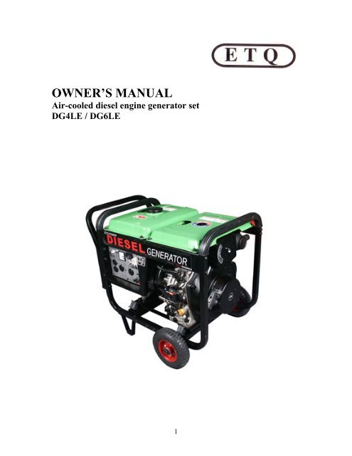
OWNER’S <strong>MANUAL</strong><br />
Air-cooled diesel engine generator set<br />
DG4LE / DG6LE<br />
1
PREFACE<br />
Thank you for purchasing products from EASTERN TOOLS & EQUIPMENT, INC. We<br />
appreciate your business. The following manual is only a guide to assist you and is not a<br />
complete or comprehensive manual of all aspects of maintaining and repairing your<br />
generator. The equipment you have purchased is a complex piece of machinery. We<br />
recommend that that you consult with a dealer if you have doubts or concerns as to your<br />
experience or ability to properly maintain or repair your equipment. You will save time<br />
and the inconvenience of having to go back to the store if you choose to write or call us<br />
concerning missing parts, service questions, operating advice, and/or assembly questions.<br />
Our air-cooled diesel generators have some of the following features:<br />
• Lightweight construction<br />
• Air cooled<br />
• Four-stroke diesel internal combustion engine<br />
• Direct fuel injection system<br />
• Recoil starter or an optional electric starter<br />
• Large fuel tank<br />
• Automatic voltage stabilizer<br />
• NFB circuit protector<br />
• AC and DC outputs<br />
• Low oil pressure sensor<br />
The ETQ air-cooled diesel generators are widely used when electrical power is scarce.<br />
Our generators provide a portable mobile solution in supplying power for field operations<br />
during project construction. Some other known applications include pipeline<br />
construction and metal welding when electrical power is not available.<br />
This manual will explain how to operate and service your generator set.<br />
If you have any questions or suggestions about this manual, please contact your local<br />
dealer or us directly. Consumers should notice that this manual might differ slightly<br />
from the actual product as more improvements are made to our products. Some of the<br />
pictures in this manual may differ slightly from the actual product as well. Eastern<br />
Tools and Equipment, Inc. reserves the right to make changes at any time without<br />
notice and without incurring any obligation.<br />
2
TABLE OF CONTENTS<br />
Page number<br />
Overall view of the generator set 4<br />
Chapter 1 Technical Specifications and Data 5<br />
1-1 Technical specifications and data 5<br />
1-2 Basic operating parameters 7<br />
1-3 General dimensions and overview of the generators 7<br />
1-4 Electric wiring diagrams for various models of generators 8<br />
Chapter 2 Operating the Diesel Generator 11<br />
2-1 Main points of safety during operation of the generator 11<br />
2-2 Preparation before operation 13<br />
2-3 Checking the operation of the diesel engine 16<br />
2-4 Starting the generator set 16<br />
2-5 Procedures for starting the generator set 19<br />
2-6 Proper operation of the generator set 21<br />
2-7 Loading 21<br />
2-8 Stopping the generator 23<br />
Chapter 3 Maintenance 24<br />
3-1 Maintenance schedules 24<br />
3-2 Storing for long periods of time 26<br />
Chapter 4 Troubleshooting 27<br />
4-1 Overhauling and troubleshooting procedures 27<br />
4-2 Questions and doubts 27<br />
Chapter 5 Generator Parts Diagrams and Listings 28<br />
Limited Warranty 34<br />
Product Registration Card 34<br />
List for comments from users 36<br />
Appendix 37<br />
1. Attached list of tools fittings, and subassemblies 37<br />
2. Attached technical documents 37<br />
3
1. Overall view of DG3LE series 3. Overall view of DG6LE series<br />
2. Overall view of DG4LE series 4. Overall view of DG6LE-3P series<br />
4
CHAPTER 1. TECHNICAL SPECIFICATIONS AND DATA<br />
Technical specifications in SI units<br />
Item Model 3LE Series 4LE Series 6LE Series 6LE-3P<br />
Series<br />
Generator Type Single phase AC generator Three phase<br />
Generator<br />
Diesel Engine<br />
Frequency (Hz) 60 60 60 60<br />
Rated power (Kw) 2.8 4.0 6.0 5.0<br />
Cont. power (kW) 2.6 3.5 5.5 4.5<br />
Voltage (AC) (V) 120 / 240<br />
Voltage (AC) (V) 12 420/240<br />
Current (DC) (A) 8.3<br />
Speed (rpm) 3600 3600 3600 3600<br />
Power factor (cos ϕ) 1.0 0.8<br />
Phase type Single-phase<br />
Number of poles 2<br />
Excitation Self-excitation voltage<br />
Insulation B<br />
Engine model ETQ170FG ETQ178FG ETQ186FG ETQ186FG<br />
Type Single-cylinder, vertical, 4-stroke, air-cooled, direct<br />
injection<br />
Output Continuous<br />
(kw)<br />
2.98 4.40 6.6 6.6<br />
Maximum<br />
(kw)<br />
3.36 4.9 7.34 7.34<br />
Bore x Stroke (mm) 70 x 55 78 x 62 86 x 70 86 x 70<br />
Displacement (cc) 219 306 418 418<br />
Cooling system Forced air cooling by flywheel fan<br />
Lubricating system Pressure splash, duplex type lubrication<br />
Lube-oil capacity .75 1.1 1.65 1.65<br />
Starting system Recoil manual start / Electric start (optional)<br />
Fuel tank capacity<br />
(L)<br />
15 15 15 15<br />
Dry weight 53 96 119 119<br />
Dimensions<br />
(LxWxH) (mm)<br />
690x470x555 690x470x555 740x500x590 740x500x59<br />
0<br />
5
Technical specifications in English units<br />
Item Model 3LE Series 4LE Series 6LE Series 6LE-3P<br />
Series<br />
Generator Type Single phase AC generator Three phase<br />
Generator<br />
Diesel Engine<br />
Frequency (Hz) 60 60 60 60<br />
Rated power (HP) 3.75 5.36 8.04 6.7<br />
Cont. power (HP) 3.49 4.69 7.37 6.04<br />
Voltage (AC) (V) 120 / 240<br />
Voltage (AC) (V) 12 420/240<br />
Current (DC) (A) 8.3<br />
Speed (rpm) 3600 3600 3600 3600<br />
Power factor (cos<br />
ϕ)<br />
1.0 0.8<br />
Phase type Single-phase<br />
Number of poles 2<br />
Excitation Self-excitation voltage<br />
Insulation B<br />
Engine model ETQ170FG ETQ178FG ETQ186FG ETQ186FG<br />
Type Single-cylinder, vertical, 4-stroke, air-cooled, direct<br />
injection<br />
Outp Continuous 4.0 5.9 8.85 8.85<br />
ut (HP)<br />
Maximum<br />
(HP)<br />
4.5 6.6 9.85 9.85<br />
Bore x Stroke (in) 2.76 x 2.17 3.01 x 2.44 3.39 x 2.76 3.39 x 2.76<br />
Displacement (cu.<br />
in)<br />
13.36 18.67 25.51 25.51<br />
Cooling system Forced air cooling by flywheel fan<br />
Lubricating system Pressure splash, duplex type lubrication<br />
Lube-oil capacity<br />
(oz)<br />
25.34 37.17 55.75 55.75<br />
Starting system Recoil manual start / Electric start (optional)<br />
Fuel tank capacity<br />
(USgal)<br />
3.96 3.96 3.96 3.96<br />
Dry weight (lb) 116 212 263 263<br />
Dimensions 27.2x18.5x 27.2x18.5x21 29.1x19.7x23 29.1x19.7x23<br />
(LxWxH) (in) 21.9 .9<br />
.2<br />
.2<br />
6
1-2 Basic operating parameters<br />
1-1.1 Under the given conditions, the generator will output the specified power in the<br />
table listed below.<br />
Table 1.<br />
Height above sea level (ft) Ambient temperature ( o F) RH<br />
0 +60 (+20 o C) 60%<br />
1-4 Electric wiring diagrams for various models of generators<br />
8<br />
Wiring diagrams for the LE models
CHAPTER 2 OPERATING THE DIESEL GENERATOR<br />
2-1 General main points of safety during operation of the generator set.<br />
In order to operate the generator set safely, please follow all the instructions provided in<br />
this manual carefully. Doing so otherwise may lead to accidents and or equipment<br />
damage.<br />
2-1.1 Fire prevention<br />
The proper fuel for the diesel generator set is light diesel fuel. Do not use gasoline,<br />
kerosene and or other fuels other than light diesel fuel. Keep all flammable fuels away<br />
from the generator as the generator may spark and ignite these gases. In order to prevent<br />
fires from occurring and to provide enough ventilation for people and the machine, keep<br />
the diesel generator at least 1.5 meters away from buildings and or other equipment.<br />
Always operate your diesel generator on a level site. If the generator is operated on an<br />
incline, the lubricating system within the engine will not perform well and may lead to<br />
failure of the engine.<br />
2-1.2 Prevention from inhaling exhaust gases<br />
Never inhale exhaust gases emitted by the engine. The exhaust gases contain toxic<br />
carbon monoxide. Never operate your generator in places with poor ventilation. In order<br />
to operate this machinery indoors, a suitable ventilation system for the building is<br />
required to draw the poisonous exhaust gases out.<br />
2-1.3 Prevention from accidental burns<br />
Never touch the muffler and its cover when the diesel engine is running. Never touch the<br />
muffler and cover after the diesel engine has been used, as the muffler remains hot for a<br />
good period of time.<br />
2-1.4 Electric shock and short circuits<br />
Never touch the generator if the generator is wet. Also never touch the generator if your<br />
hand is wet. Never operate your generator if the weather conditions call for any type of<br />
precipitation such as rain, snow, or fog. To prevent electrical shocks, the generator<br />
should be grounded. Use a lead to connect the grounding end of the generator to the<br />
grounding surface of choice. Please refer to Fig. 2-1 and Fig. 2-2 before beginning to use<br />
the electric generator.<br />
11
Fig 2-1 Fig 2-2<br />
2-1.5 Other safety points<br />
Note: When connecting devices to the generator,<br />
make sure all other devices are rated lower than<br />
the generators output. Any generator socket<br />
should not be overloaded over its regulated limit<br />
Before operating this generator, all operators should have a good knowledge of how to<br />
break the circuit if any accidents occur. Also, all operators should be familiar with all the<br />
switches and functions of the generator before using this machine. While operating the<br />
generator, wear safe shoes and suitable clothes during operation. Always keep children<br />
and animals away from the generator.<br />
2-1.6 Battery<br />
The electrolytic liquid of the battery also known as battery acid contains sulfuric acid. In<br />
order to protect your eyes, skin, and clothing, wear protective gear when working with<br />
the battery. If you come in contact with the electrolytic liquid, wash it immediately with<br />
clean water. Also, if the electrolytic liquid comes in contact with your eyes, see a doctor<br />
immediately.<br />
12
2-2 Preparation before operation<br />
2-2.1 Fuel choices and fuel treatment<br />
Fuel tank<br />
Use only light diesel fuel. The fuel<br />
should be filtered clean. Never let<br />
dust and water mix with fuel in the<br />
fuel tank. Otherwise it will clog the<br />
fuel lines and oil nozzles. It may also<br />
damage your pressure pump.<br />
Note: It is dangerous to overfill the<br />
fuel tank. Never exceed the red piston<br />
in the filter.<br />
a. After purchasing fuel, put it<br />
into a drum and let it sit for 3-<br />
4 days.<br />
b. 3-4 days later, insert half of<br />
the fuel sucker into the drum,<br />
(water and impurities stay in<br />
the lower portion of the<br />
drum)<br />
13<br />
Air filter element<br />
Do not wash the air filter. The<br />
element is made of dry material,<br />
which does not permit washing.<br />
When the output of the diesel<br />
engine is bad or the color of the<br />
exhaust gas is abnormal, replace the<br />
air filter element. Never start the<br />
diesel engine without the air filter.<br />
Note:<br />
Never smoke near the opening of<br />
the fuel tank. Do not let sparks get<br />
near the fuel or fuel tank and do not<br />
overfill tank. After filling, tighten<br />
the fuel cap.
2-2.2 Filling engine oil<br />
Remove the dipstick from the engine<br />
Make sure the generator is on level<br />
ground, and fill the engine with 15W40<br />
engine oil. Put the dipstick back into the<br />
hole to check the engine oil level.<br />
Engine oil is the most important factor in determining the life of your generator engine.<br />
If you use poor engine oil or if you don’t change the oil regularly, the piston and cylinder<br />
will wear easily or seize up. Also, the life of the other parts in your engine such as<br />
bearings, and other rotating parts will shorten considerably.<br />
Although there is an alarm system to check for low oil pressure, it is always a good idea<br />
to check the amount of oil inside the engine. If the oil level is low, fill it before starting<br />
the engine. A good time to drain the oil from the engine is when the diesel engine is still<br />
hot. If the engine is fully cooled, it is more difficult to drain all the oil out or some<br />
impurities will remain in the engine.<br />
14
2-2.3 Checking the air filter<br />
(1) Loosen the butterfly nut, take the<br />
cover of the air filter off and take<br />
the air filter element out.<br />
Butterfly nut<br />
Air filter cover<br />
Do not use detergent to wash the air<br />
filter element. When the<br />
performance of the engine decreases<br />
or when the color of the exhaust<br />
gases is bad, exchange the filter<br />
element. Never start the engine<br />
without the air filter as foreign<br />
objects may enter the intake and<br />
damage the engine.<br />
(2) After replacing the air filter<br />
element, replace the cover and<br />
tighten the butterfly nut firmly.<br />
2-2.4 Checking the generator welder<br />
15<br />
(Note: Only certain welder generator sets<br />
have an electric fan incorporated on them.)<br />
Before starting the generator, make<br />
sure the air switch is in the “Off”<br />
position. Starting the generator with<br />
the switch in the “On” switch is very<br />
dangerous.<br />
The generator should be grounded in<br />
order to prevent electric shock.<br />
Use dry compressed air (with<br />
pressure about 1.96 x 10⁵ Pa) to<br />
blow the dust out in the electric<br />
control cabinet and at the surface of<br />
the generator. Check to see how<br />
clean the surface of the sliding ring<br />
is. Check the pressure of the carbon<br />
brush. Also, check whether the<br />
position of the carbon brush at the<br />
slide rig is correct and the fixture is<br />
reliable with a good contact.<br />
According to the electric wiring<br />
diagram, check to see whether the<br />
connecting wire is correct and the<br />
connected place is firm.<br />
Use a 500 M Ω meter to measure the<br />
insulation resistance of the electrical<br />
part. The resistance should be no<br />
less than 5M Ω. When measuring<br />
devices, make sure the AVR is<br />
turned off. Otherwise, it will burn<br />
the AVR. (For the low noise set, the<br />
inspection may not be performed).<br />
2-2.5 The fuel and oil in a new<br />
engine is drained before sold.
Before you start the engine, please<br />
fill the fuel tank and engine oil first.<br />
Then, check to see if there are air<br />
bubbles in the engine. If there are,<br />
follow these procedures. Loosen the<br />
connecting nut between the oil<br />
injection pump and oil pipe. Bleed<br />
the air from the system until there<br />
are no more bubbles. Then replace<br />
the connecting nut and tighten it.<br />
2-3 Checking the operation of the<br />
diesel engine<br />
2-3.1 Low-pressure alarm system.<br />
ETQ diesel engines have a lowpressure<br />
sensor system where if<br />
the oil pressure drops too low,<br />
the sensor will shut the engine<br />
off. The purpose of having this<br />
system is to ensure that the<br />
engine does not seize up. If there<br />
is not enough oil in the engine,<br />
the temperature of the oil will be<br />
raised too high. On the contrary,<br />
if there is too much oil in the<br />
engine, the engine oil can slow<br />
the engine down considerably.<br />
2-3.2 How to open the case door/cover<br />
(1) Open the case door: turn the<br />
handle counterclockwise and<br />
open the door. Do these<br />
checks daily.<br />
Knob handle<br />
(2) Loosen the outer cover bolt<br />
of the air filter and outer<br />
cover of the oil nozzle, and<br />
then check the air filter.<br />
(3) Check the outer cover of the<br />
oil nozzle. Loosen the<br />
16<br />
butterfly nut and open the<br />
outer cover.<br />
2-3.3 Engine break in<br />
When you purchase a brand new<br />
engine, the engine must be<br />
properly broken in. The break in<br />
period is about 20 hours.<br />
(1) Avoid overloading the<br />
engine when brand new<br />
(2) Change the engine oil<br />
according to specifications.<br />
An oil change for a brand<br />
new engine is about 20 hours<br />
or every month, an older<br />
engine, the oil change is<br />
about 100 hours or three<br />
months.<br />
2-4 Starting the generator set<br />
2-4.1 Manual starting.<br />
Start the engine in accordance with<br />
procedures below:<br />
Fuel switch<br />
(1) Put the fuel switch in the<br />
“On” position.<br />
(2) Turn the handle of the<br />
engine to the “RUN”
position.<br />
(3) Pull the recoil starter handle<br />
out until you feel resistance.<br />
It will reset to its original<br />
position automatically. The<br />
handle should be reset into<br />
its recoil device slowly to<br />
prolong the life of the engine<br />
starter.<br />
(4) In cold climate, it is difficult<br />
to start the engine. To<br />
remedy this, pull the rubber<br />
plug out from the rocker of<br />
the diesel engine and fill 2<br />
ml of engine oil. Before<br />
starting, put the rubber plug<br />
back in place. If you don’t<br />
put the rubber plug back in<br />
place, rain, dust and other<br />
dirt can enter into the diesel<br />
engine. It will cause the<br />
parts inside the diesel engine<br />
to wear quickly and lead to<br />
engine failure.<br />
2-4.2 Electric starting<br />
The procedures for preparing to start the<br />
engine are the same as the manual<br />
starting engine.<br />
2-4.3 Battery<br />
17<br />
1. Insert key into ignition and<br />
put it in the “off” position.<br />
2. Put the speed handle in the<br />
“Run” position.<br />
3. Turn the start switch<br />
clockwise to the “START”<br />
position; (to set the silent<br />
type, first turn it clockwise to<br />
the “RUN” (ON) position for<br />
1-2 seconds. The<br />
electromagnetic iron will be<br />
triggered, now turn it<br />
clockwise to the “START”<br />
position.<br />
4. After the diesel engine is<br />
started, remove your hand<br />
from the switch handle; the<br />
switch will automatically<br />
reset itself to the “ON”<br />
position.<br />
5. If the engine is not starting<br />
after 10 seconds of cranking,<br />
wait about 15 seconds before<br />
trying it again. If you crank<br />
to long, the voltage of the<br />
battery will drop. This can<br />
lead to improper ignition.<br />
When the diesel engine is<br />
operating, let the ignition<br />
retain on the “ON” position.<br />
Note:<br />
If you crank the starter to long, the<br />
battery may be drained too much to<br />
provide enough energy for proper<br />
engine ignition. Also, when the diesel<br />
engine is operating, let the key retain<br />
in the “ON” position.
Important Notice: All of our units come with a dry battery for shipping safety purposes.<br />
In order to get your generator started for the first time; the battery must be filled with<br />
battery acid which can be purchased at a local automotive supply store and slowly<br />
charged (trickle charged) for a day. After charging, the battery may be used. To properly<br />
maintain your battery; check the height of the battery acid once a month. If the level of<br />
the liquid drops too low, fill it with distilled water until it reaches the high mark. If there<br />
is not enough battery acid, then the diesel engine cannot be started. It is important to<br />
keep the liquid level between the high and low limits.<br />
If the level in the battery is to high, the liquid may flow out and end up on surrounding<br />
parts resulting in corrosion of these parts.<br />
Note: Avoid too much or too little of battery acid. Check and fill it once a month if<br />
necessary.<br />
18
2-5 Procedures for starting the generator set<br />
This procedure applies to the L series recoil starting style models.<br />
19
2-6 Proper operation of the generator<br />
set<br />
2-6.1 Operating the diesel engine<br />
1. Pre-heat the diesel engine for<br />
3 minutes under no load<br />
conditions.<br />
2. First check the height of the<br />
lubricating oil level, if it is<br />
low, refill it. Our diesel<br />
engines are equipped with an<br />
alarm system that will notify<br />
you if the oil pressure is too<br />
low. The alarm system will<br />
shut down the engine if the<br />
oil pressure is too low.<br />
3. Do not adjust the speed limit<br />
regulation bolt or the fuel<br />
adjustment bolt. These bolts<br />
have been set by the factory<br />
already, changing them will<br />
affect the properties of the<br />
engine<br />
performance.<br />
Fuel adjustment bolt<br />
Fuel adjustment bolt<br />
Speed limit bolt<br />
High-pressure<br />
fuel pipe nut Fuel adjustment<br />
bolt<br />
21<br />
2-6.2 Checks during engine operation<br />
2-7 Loading<br />
1. Check to see if there are<br />
abnormal noises.<br />
2. Check to see if the<br />
performance is good or bad<br />
3. Check the color of the<br />
exhaust gases (whether it is<br />
too black or too white). If<br />
any of these conditions exist,<br />
stop the engine and find the<br />
cause of the problem. If no<br />
problems are found, please<br />
contact your local dealer or<br />
our nearest company branch.<br />
2-7.1 Load conditions<br />
Exert loads in accordance with<br />
the specified parameters.<br />
2-7.2 Output of electricity<br />
1. Raise the revolutions per<br />
minute (turn the speed handle<br />
to the max setting) of the<br />
generator to get the<br />
maximum power out of the<br />
generator. If not, the<br />
automatic voltage regulator<br />
device will excite and doing<br />
this for long periods of time<br />
will cause the AVR to burn.<br />
For the rated speed of the<br />
generator, please refer to<br />
Chapter 1, item 1-1 technical<br />
specification and data.<br />
2. Observe the pointer of the<br />
voltmeter, it should point to<br />
230 V ± 5% (50Hz). (For 60<br />
Hz set, it will be 240 V ±<br />
5%). Meanwhile put the<br />
switch in the GEN<br />
(generator) position. The AC
voltage from the socket of the<br />
power supply can be output.<br />
3. When connecting devices to<br />
the generator, make sure to<br />
connect these devices in<br />
order. Connect the large<br />
loads onto the generator first.<br />
If everything is functional,<br />
smaller loads can then be<br />
added. If the generator shuts<br />
off, it may be because the<br />
load being drawn by all the<br />
various devices are too high.<br />
In this event, decrease the<br />
number of small devices until<br />
everything is functional. The<br />
total drawn power should not<br />
exceed the maximum output<br />
power of the generator.<br />
Please see Table 1-1 for<br />
Table 2-1.<br />
22<br />
technical specifications of<br />
what the generator can<br />
output. In order to reset the<br />
generator after overdrawn<br />
power, let it sit for several<br />
minutes. If the indication of<br />
the voltmeter is too high or<br />
too low, adjust the speed<br />
accordingly. If there are<br />
problems, stop the generator<br />
immediately and fix the<br />
issue.<br />
4. During operation, the<br />
generator should be in a place<br />
that has very good<br />
ventilation. Never cover the<br />
engine to solve a ventilation<br />
problem, as this will damage<br />
your equipment.<br />
Note: Do not start more than two devices simultaneously. Each device should be<br />
started one by one to prevent overloading the generator.<br />
The generator should be running at 3600 revolutions per minute in order to achieve<br />
the (60 Hz) frequency. The speed of the engine can be adjusted from the speed<br />
governor.<br />
2-7.3 Charging the battery<br />
1. For the electric starter on the generator welder, the 12V battery is<br />
automatically charged through the regulator on the side of the engine when it<br />
is running.<br />
2. If the generator is not used for long periods of time, the battery should be<br />
disconnected to avoid energy loss from the battery.<br />
3. Do not connect the negative and positive terminals of the battery together at<br />
any time. Doing so will damage the battery and cause serious injuries.<br />
4. Do not reverse the polarities when attaching the battery cables to the battery.<br />
Doing so will damage both the battery and the electric starter.<br />
5. When charging the battery, the battery produces flammable gases. Do not<br />
smoke, let flames, and sparks get near the battery while it is charging as this<br />
may cause a fire. To avoid sparking while connecting the cables to the<br />
battery, first, connect the cables to the battery then to the motor. To<br />
disconnect battery cables, first disconnect the motor end of the cable.
2-8 Stopping the generator<br />
1. Take the electrical load off<br />
the generator.<br />
2. Put the speed handle in the<br />
“RUN” position and let the<br />
engine run for 3 minutes after<br />
unloading. Do not stop the<br />
diesel engine immediately let<br />
it warm down. Stopping the<br />
diesel engine suddenly may<br />
raise the temperature of the<br />
engine abnormally and lock<br />
the nozzle and damage the<br />
diesel engine.<br />
Speed handle<br />
Note:<br />
1. If the speed handle is in the<br />
“Stop position and the<br />
engine is still running, turn<br />
the fuel switch to the “OFF”<br />
position or loosen the high<br />
pressure oil pipe nut. The<br />
engine could be stopped<br />
more than one-way other<br />
than the speed handle way.<br />
2. If you cannot stop the<br />
engine with a load on it,<br />
then remove the load first<br />
than stop the engine.<br />
3. Press down on the brake<br />
handle<br />
4. If equipped with an electric<br />
starter, turn the key to the<br />
“Off” position<br />
5. Put the fuel handle to the “S”<br />
position<br />
23<br />
6. Finally, pull slowly on the<br />
recoil handle until you feel<br />
resistance (this is when the<br />
piston is on the compression<br />
stroke, where the intake and<br />
exhaust valves are closed).<br />
What this does is prevent the<br />
engine from rusting when not<br />
in use.
3-1 Maintenance schedules<br />
CHAPTER 3 MAINTENANCE<br />
Keeping your generator well maintained will prolong the life of your generator.<br />
Everything needs to be checked including the diesel engine, generator, control cabinet,<br />
and frame. For overhauling procedures, please refer to the instruction manual of the<br />
relative subassembly. If you need these manuals, please call our company and we will<br />
send you one.<br />
Before starting the maintenance, make sure the diesel engine is off.<br />
Please refer to the Table 3-1 for the proper maintenance schedule.<br />
Table 3-1. Maintenance schedule for diesel welder generator set<br />
24
3-1.1 Changing the engine oil (every<br />
100 hours)<br />
Take the oil cover off. Remove the oil<br />
drain plug when the diesel engine is still<br />
hot. Be careful of hot oil and hot engine<br />
as you may get burned. The bolt is<br />
located at the bottom of the cylinder.<br />
After draining the oil, put the bolt back<br />
and tighten it. Then fill with the proper<br />
engine oil to the proper level.<br />
High-pressure<br />
fuel pipe bolt<br />
Oil drain bolt<br />
3-1.2 Air filter maintenance schedule<br />
1. Clean air-filter every 6<br />
months or 500 hours of<br />
operation.<br />
2. If necessary, exchange it.<br />
3. Do not use detergent to clean<br />
air filter element.<br />
Note:<br />
Never start the engine without<br />
the air filter. This can cause<br />
serious damage to the engine if<br />
foreign objects enter the intake<br />
system. Always change the air<br />
filter on time.<br />
25<br />
3-1.3 Fuel filter maintenance<br />
1. The fuel filter should be cleaned<br />
often to keep the engine running<br />
at maximum performance.<br />
2. The recommended time period<br />
for cleaning the fuel filter is 6<br />
months or 500 hours of<br />
operation.<br />
a. To do this, first drain the<br />
fuel from the fuel tank.<br />
b. Loosen the small screws<br />
on the fuel switch and<br />
remove the fuel filter<br />
form the port. Use diesel<br />
Dipstick fuel to clean the fuel<br />
filter. Also, remove the<br />
fuel injector and clean the<br />
carbon deposit around it.<br />
The recommended time<br />
period for this is 3<br />
months or 100 hours.<br />
3-1.4 Cylinder head bolt tensions<br />
The cylinder head bolts should be<br />
tightened to specifications please refer to<br />
the diesel engine manual for<br />
specifications and the special tools<br />
required to do this.<br />
3-1.5 Battery check<br />
Make sure the battery acid is full. The<br />
engine uses a 12V battery. Due to<br />
numerous starting cycles, the battery<br />
acid may be used up. Also, before<br />
filling, verify that the battery is not<br />
damaged in any way. Add distilled<br />
water to the battery when filling.<br />
Perform checks on the battery once a<br />
month.
3-2 Storing for long periods of time<br />
If your generator needs to be stored for long periods of time, the following preparations<br />
should be made.<br />
1. Start the diesel engine for 3 minutes then stop it.<br />
2. When the engine is still hot, change the engine oil with new engine oil of the<br />
proper grade.<br />
3. Pull the rubber plug out of the cylinder head cover and put 2CC of lubricating oil<br />
in it, then cover the plughole up again.<br />
4. For manual starting generator welders, press the decompression handle down and<br />
pull the recoil handle 2 or 3 times. This pushes the intake out. (Do not start the<br />
engine)<br />
5. For electric started generator welders, press the decompression handle down and<br />
crank the engine for 2-3 seconds. To do this, put the starter switch in the “Start”<br />
position. (Do not start the diesel engine)<br />
6. Finally, pull the recoil starter until you feel resistance; this is when the piston is<br />
on the compression stroke where the intake and exhaust valves are closed.<br />
Having the intake and exhaust valves closed will prevent rust, as moisture cannot<br />
get inside the combustion chamber.<br />
7. Clean the engine and store it in a dry place.<br />
26
4-1 Troubleshooting procedures<br />
CHAPTER 4 TROUBLESHOOTING<br />
If you are still having trouble, please contact with your nearest dealer or with our<br />
company directly if necessary.<br />
4-2 Questions and doubts<br />
If you do not understand anything or have any questions, please feel free to contact your<br />
local dealer or with our company directly. Below is a list of some information you<br />
should have ready before contacting your local dealer or us.<br />
1. Model of diesel engine generator and engine model number.<br />
2. State of residency<br />
3. Number of hours of operating equipment along with the problem that occurred.<br />
4. A detailed condition and time when the problem occurred, in other words, climate<br />
and atmosphere<br />
27
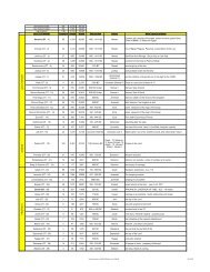
CHAPTER 5 GENERATOR PARTS DIAGRAMS AND LISTINGS<br />
Figure 5-2. Overall view of engine generator assembly<br />
Table 5-1. Please refer to figure 5-2 for illustration<br />
Number Part Description Quantity Part Number (4LE / 6LE)<br />
1 ETQ series diesel engine 1 ETQ4LE1 / ETQ6LE1<br />
2 Starter Motor 1 ETQ4LE2 / ETQ6LE2<br />
3 Flywheel generator 1 ETQ4LE3 / ETQ6LE3<br />
4 Bolt 2 ETQ4LE4 / ETQ6LE4<br />
5 Voltage Regulator 1 ETQ4LE5 / ETQ6LE5<br />
6 Battery Cable (red) 1 ETQ4LE6 / ETQ6LE6<br />
7 Battery Cable (black) 1 ETQ4LE7 / ETQ6LE7<br />
8 Battery 1 ETQ4LE8 / ETQ6LE8<br />
9 Oil level sensor 1 ETQ4LE9 / ETQ6LE9<br />
10 Output panel assembly 1 ETQ4LE10 / ETQ6LE10<br />
11 Throttle cable 2 ETQ4LE11 / ETQ6LE11<br />
12 Connector assembly 1 ETQ4LE12 / ETQ6LE12<br />
13 Capacitor 1 ETQ4LE13 / ETQ6LE13<br />
14 Bolt 2 ETQ4LE14 / ETQ6LE14<br />
15 Voltage Regulator Bracket 1 ETQ4LE15 / ETQ6LE15<br />
16 Bolt 2 ETQ4LE16 / ETQ6LE16<br />
28
Figure 5-3. Exploded view of frame assembly<br />
29
Table 5-2. Please refer to figure 5-3.<br />
Number Part Description Quantity Part Number (4LE / 6LE)<br />
1 M6 x 25 Bolt 4 ETQ4LE17 / ETQ6LE17<br />
2 M6 Flat washer 4 ETQ4LE18 / ETQ6LE18<br />
3 Shock absorber 4 ETQ4LE19 / ETQ6LE19<br />
4 Washer 4 ETQ4LE20 / ETQ6LE20<br />
5 M6 Nut 4 ETQ4LE21 / ETQ6LE21<br />
6 Engine cover 1 ETQ4LE22 / ETQ6LE22<br />
7 Rubber cover 1 ETQ4LE23 / ETQ6LE23<br />
8 Handrail 1 ETQ4LE24 / ETQ6LE24<br />
9 M8 x 65 Bolt 4 ETQ4LE25 / ETQ6LE25<br />
10 Plastic gasket 4 ETQ4LE26 / ETQ6LE26<br />
11 Flat washer M8 4 ETQ4LE27 / ETQ6LE27<br />
12 Spring washer 4 ETQ4LE28 / ETQ6LE28<br />
13 M8 Nut 4 ETQ4LE29 / ETQ6LE29<br />
14 Battery tie down 1 ETQ4LE30 / ETQ6LE30<br />
15 M6 Nut 2 ETQ4LE31 / ETQ6LE31<br />
16 Tie down hooks 2 ETQ4LE32 / ETQ6LE32<br />
17 Battery 1 ETQ4LE33 / ETQ6LE33<br />
18 M8x12 bolts 2 ETQ4LE34 / ETQ6LE34<br />
19 Rubber absorber 1 ETQ4LE35 / ETQ6LE35<br />
20 Motor mount 1 ETQ4LE36 / ETQ6LE36<br />
21 Battery tray 1 ETQ4LE37 / ETQ6LE37<br />
22 M6 Nut 1 ETQ4LE38 / ETQ6LE38<br />
23 Spring washer 6 1 ETQ4LE39 / ETQ6LE39<br />
24 M6 x 35 Bolt 1 ETQ4LE40 / ETQ6LE40<br />
25 M10 Nut 2 ETQ4LE41 / ETQ6LE41<br />
26 Spring washer 10 2 ETQ4LE42 / ETQ6LE42<br />
27 Flat washer 10 2 ETQ4LE43 / ETQ6LE43<br />
28 M10 x 20 2 ETQ4LE44 / ETQ6LE44<br />
29 Bracket 1 ETQ4LE45 / ETQ6LE45<br />
30 M10 Nut 4 ETQ4LE46 / ETQ6LE46<br />
31 Spring washer 10 4 ETQ4LE47 / ETQ6LE47<br />
32 Flat washer 10 4 ETQ4LE48 / ETQ6LE48<br />
33 Rubber mounts 4 ETQ4LE49 / ETQ6LE49<br />
34 Flat washer 10 4 ETQ4LE50 / ETQ6LE50<br />
35 Spring washer 10 4 ETQ4LE51 / ETQ6LE51<br />
36 M10 Nut 4 ETQ4LE52 / ETQ6LE52<br />
37 Axle 1 ETQ4LE53 / ETQ6LE53<br />
38 M6 Nut 4 ETQ4LE54 / ETQ6LE54<br />
39 U bolt 2 ETQ4LE55 / ETQ6LE55<br />
40 Flat washer 20 2 ETQ4LE56 / ETQ6LE56<br />
41 Split pin 32 x 32 2 ETQ4LE57 / ETQ6LE57<br />
42 Wheel 2 ETQ4LE58 / ETQ6LE58<br />
43 Solenoid cable bolts 2 ETQ4LE59 / ETQ6LE59<br />
44 Solenoid 1 ETQ4LE60 / ETQ6LE60<br />
45 Solenoid bracket 1 ETQ4LE61 / ETQ6LE61<br />
46 Bolts 4 ETQ4LE62 / ETQ6LE62<br />
47 Throttle cable 1 ETQ4LE63 / ETQ6LE63<br />
48 M8 x 40 Bolt 4 ETQ4LE64 / ETQ6LE64<br />
49 M8 Nut 4 ETQ4LE65 / ETQ6LE65<br />
50 Bracket 2 ETQ4LE66 / ETQ6LE66<br />
51 Bracket 1 ETQ4LE67 / ETQ6LE67<br />
52 Rubber insulator 2 ETQ4LE68 / ETQ6LE68<br />
30
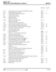
Figure 5-4. Electric panel parts drawing<br />
Table 5-3. Please refer to Figure 5-4<br />
Number Part Description Quantity Part Number (4LE /6LE)<br />
1 Positive DC port 1 ETQ4LE69 / ETQ6LE69<br />
2 Negative DC port 1 ETQ4LE70 / ETQ6LE70<br />
3 Grounded bolt 1 ETQ4LE71 / ETQ6LE71<br />
4 Bolt 2 ETQ4LE72 / ETQ6LE72<br />
5 Large Nut 1 ETQ4LE73 / ETQ6LE73<br />
6 Bolt 2 ETQ4LE74 / ETQ6LE74<br />
7 Bolt 2 ETQ4LE75 / ETQ6LE75<br />
8 Large Nut 1 ETQ4LE76 / ETQ6LE76<br />
9 Current Adjusting Switch 1 ETQ4LE77 / ETQ6LE77<br />
10 3 prong Socket 2 ETQ4LE78 / ETQ6LE78<br />
11 Bolt 6 ETQ4LE79 / ETQ6LE79<br />
12 Electric panel bolt 6 ETQ4LE80 / ETQ6LE80<br />
13 Electric Panel 1 ETQ4LE81 / ETQ6LE81<br />
14 Starter switch 1 ETQ4LE82 / ETQ6LE82<br />
15 Large nut 6 ETQ4LE83 / ETQ6LE83<br />
16 Oil alert lamp 1 ETQ4LE84 / ETQ6LE84<br />
17 Hour meter 1 ETQ4LE85 / ETQ6LE85<br />
18 Hour meter bolts 2 ETQ4LE86 / ETQ6LE86<br />
19 DC Fuse 1 ETQ4LE87 / ETQ6LE87<br />
20 Voltmeter 1 ETQ4LE88 / ETQ6LE88<br />
21 Nut 2 ETQ4LE89 / ETQ6LE89<br />
22 4 prong socket 1 ETQ4LE90 / ETQ6LE90<br />
23 Breaker bracket 1 ETQ4LE91 / ETQ6LE91<br />
24 Nut 2 ETQ4LE92 / ETQ6LE92<br />
25 Breaker 1 ETQ4LE93 / ETQ6LE93<br />
26 Wiring harness 1 ETQ4LE94 / ETQ6LE94<br />
27 Electrical box 1 ETQ4LE95 / ETQ6LE95<br />
31
Figure 5-5. Generator head assembly<br />
Table 5-4. Please refer to figure 5-5<br />
Number Part Description Quantity Part Number (4LE / 6LE)<br />
1 Front end cover 1 ETQ4LE96 / ETQ6LE96<br />
2 Diode 2 ETQ4LE97 / ETQ6LE97<br />
3 M4 x 8 Bolt 2 ETQ4LE98 / ETQ6LE98<br />
4 Fan Blade 1 ETQ4LE99 / ETQ6LE99<br />
5 Bearing 1 ETQ4LE100 / ETQ6LE100<br />
6 Rotor Unit 1 ETQ4LE101 / ETQ6LE101<br />
7 Center bolt 1 ETQ4LE102 / ETQ6LE102<br />
8 Motor cover 1 ETQ4LE103 / ETQ6LE103<br />
9 Stator 1 ETQ4LE104 / ETQ6LE104<br />
10 Long bolt 4 ETQ4LE105 / ETQ6LE105<br />
11 Capacitor 1 ETQ4LE106 / ETQ6LE106<br />
12 Wiring Seat 1 ETQ4LE107 / ETQ6LE107<br />
13 M5 x 15 Bolt 6 ETQ4LE108 / ETQ6LE108<br />
14 Stator Unit 1 ETQ4LE109 / ETQ6LE109<br />
15 Dust Cover 1 ETQ4LE110 / ETQ6LE110<br />
32
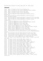
Figure 5-6. Fuel system components<br />
Table 5-5. Please refer to figure 5-6.<br />
Number Part Description Quantity Part Number (4LE / 6LE)<br />
1 Fuel Cap 1 ETQ4LE111 / ETQ6LE111<br />
2 Seal 1 ETQ4LE112 / ETQ6LE112<br />
3 Filtering cup 1 ETQ4LE113 / ETQ6LE113<br />
4 M5 x 10 screw 2 ETQ4LE114 / ETQ6LE114<br />
5 Fuel lever indicator 1 ETQ4LE115 / ETQ6LE115<br />
6 M6 x 25 Bolt 4 ETQ4LE116 / ETQ6LE116<br />
7 Large flat washer 6 4 ETQ4LE117 / ETQ6LE117<br />
8 Fuel tank lining 4 ETQ4LE118 / ETQ6LE118<br />
9 Shock absorbing gasket 4 ETQ4LE119 / ETQ6LE119<br />
10 Fuel tank 1 ETQ4LE120 / ETQ6LE120<br />
11 M6 Nut 4 ETQ4LE121 / ETQ6LE121<br />
12 O ring seal 1 ETQ4LE122 / ETQ6LE122<br />
13 Fuel tank filter 1 ETQ4LE123 / ETQ6LE123<br />
14 O ring gasket 1 ETQ4LE124 / ETQ6LE124<br />
15 Fuel filter cover 1 ETQ4LE125 / ETQ6LE125<br />
16 Cover 1 ETQ4LE126 / ETQ6LE126<br />
17 Wing nut 1 ETQ4LE127 / ETQ6LE127<br />
18 Fuel line 2 ETQ4LE128 / ETQ6LE128<br />
19 Fuel inlet pipe 1 ETQ4LE129 / ETQ6LE129<br />
20 High pressure fuel pump 1 ETQ4LE130 / ETQ6LE130<br />
21 High pressure fuel pipe 1 ETQ4LE131 / ETQ6LE131<br />
22 Fuel injector 1 ETQ4LE132 / ETQ6LE132<br />
23 Overfill tube 2 ETQ4LE133 / ETQ6LE133<br />
24 Fuel overfill pipe 1 ETQ4LE134 / ETQ6LE134<br />
33
LIMITED WARRANTY<br />
Eastern Tools & Equipment, Inc. will repair or replace, free of charge, any part or parts of the generator that are<br />
defective in material or workmanship or both. Transportation charges on parts submitted for repair or replacement<br />
under this Warranty must be borne by purchaser. This warranty is effective for the time period and subject to the<br />
conditions provided for in this policy. For warranty service, find the nearest Authorized Service Dealer by contacting<br />
the place of purchase or Eastern Tools & Equipment, Inc. THERE IS NO OTHER EXPRESSED WARRANTY.<br />
IMPLIED WARRANTIES, INCLUDING THOSE OF MERCHANTABILITY AND FITNESS FOR A<br />
PARTICULAR PURPOSE, ARE LIMITED TO ONE YEAR FROM PURCHASE, OR TO THE EXTENT<br />
PERMITED BY LAW ANY AND ALL IMPLIED WARRANTIES ARE EXCLUDED. LIABILITY FOR<br />
CONSEQUENTIAL DAMAGES UNDER ANY AND ALL WARRANTIES ARE EXCLUDED TO THE EXTENT<br />
EXCLUSION IS PERMITTED BY LAW. Some states do not allow limitations on how long an implied warranty lasts,<br />
and some states do not allow the exclusion or limitation of incidental or consequential damages, so the above limitation<br />
and exclusion may not apply to you. This warranty gives you specific legal rights and you may also have other rights,<br />
which vary from state to state.<br />
34<br />
Eastern Tools & Equipment, Inc.<br />
WARRANTY PERIOD***<br />
WITHIN U.S.A AND CANADA OUTSIDE U.S.A. AND CANADA<br />
ENGINES CONSUMER COMMERCIAL CONSUMER COMMERCIAL<br />
DIESEL<br />
GENERATOR<br />
USE<br />
1 year<br />
or 1000 hours<br />
About Your Product Warranty<br />
USA<br />
1 year<br />
or 1000 hours<br />
USE<br />
1 year<br />
or 1000 hours<br />
USE<br />
1 year<br />
or 1000 hours<br />
Eastern Tools & Equipment, Inc. welcomes warranty repair and apologizes to you for being inconvenienced. Any<br />
Authorized Service Dealer may perform warranty repairs. Most warranty repairs are handled routinely, but sometimes<br />
warranty service may be inappropriate. For example, warranty would not apply if an engine is damaged because of<br />
misuse, lack of routine maintenance, shipping, handling, warehousing and improper installation. Similarly, warranty is<br />
void if the serial number on the engine has been removed or if the engine has been altered or modified. If a customer<br />
differs with the decision of the Service Dealer, an investigation will be made to determine whether the warranty<br />
applies. Ask the Service Dealer to submit all supporting facts to his Distributor or the factory for review. If the<br />
distributor or the factory decides that the claim is justified, the customer will be fully reimbursed for those items that<br />
are defective. To avoid misunderstanding, which might occur between the customer and the dealer, listed below are<br />
some of the causes of engine failure that the warranty does not cover.<br />
Normal wear:<br />
Engines and generators, like all mechanical devices, need periodic parts service and replacement to perform well.<br />
Warranty will not cover repair when normal use has exhausted the life of a part of an engine.
Improper maintenance:<br />
The life of an engine or your equipment depends upon the conditions under which it operates, and the care it receives.<br />
Some applications, such as tillers, pumps, and rotary movers, are very often used in dusty or dirty conditions, which<br />
can cause what appears to be premature, wear. Such wear, when caused by dirt, dust, spark pug cleaning grit, or other<br />
abrasive material that has entered the engine because of improper maintenance is is not covered by warranty.<br />
35
List for comments from users<br />
Name of user<br />
Address of user<br />
Place of purchase<br />
Packaging conditions<br />
Operating conditions<br />
Parts Conditions<br />
Malfunction problem<br />
Opinions or suggestions<br />
Note: Please mail the above card to: Eastern Tools & Equipment, Inc.<br />
12220 Rivera Rd, Suite B<br />
Whittier, CA 90606<br />
36<br />
Date of<br />
Manufacture<br />
Model Number<br />
Occupation
Appendix:<br />
1. Attached list of tools, fittings, and subassemblies<br />
Order No. Name Qty Remarks<br />
1 Air-cooled diesel welder and generator set 1<br />
2 Kit 1<br />
3 Plastic cover 1<br />
4 Plug and power supply 1<br />
2. Attached technical documents<br />
Order No. Name Qty Remarks<br />
1 Air cooled diesel welder and generator<br />
manual<br />
1<br />
2 Diesel engine instruction manual 1<br />
3 Diesel engine parts listing 1<br />
4 Certificate of Quality 1<br />
5 Packing List 1<br />
37
EASTERN TOOLS & EQUIPMENT, INC.<br />
TEL: 1-626-960-6299<br />
FAX: 1-626-960-6244<br />
WEB SITE.http://easterntools.com<br />
38