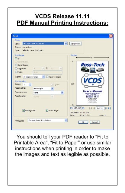
VCDS Release 11.11 PDF Manual Printing Instructions: - Ross-Tech
VCDS Release 11.11 PDF Manual Printing Instructions: - Ross-Tech
VCDS Release 11.11 PDF Manual Printing Instructions: - Ross-Tech

You also want an ePaper? Increase the reach of your titles
YUMPU automatically turns print PDFs into web optimized ePapers that Google loves.
<strong>VCDS</strong> <strong>Release</strong> <strong>11.11</strong><br />
<strong>PDF</strong> <strong>Manual</strong> <strong>Printing</strong> <strong>Instructions</strong>:<br />
You should tell your <strong>PDF</strong> reader to "Fit to<br />
Printable Area", “Fit to Paper” or use similar<br />
instructions when printing in order to make<br />
the images and text as legible as possible.
User’s <strong>Manual</strong><br />
Diagnostic Software for<br />
VW/Audi/SEAT/Skoda<br />
<strong>Release</strong> <strong>11.11</strong><br />
Copyright (c) 2000-2012<br />
by <strong>Ross</strong>-<strong>Tech</strong>, LLC.<br />
881 Sumneytown Pike<br />
Lansdale, PA 19446<br />
+1-267-638-2300<br />
www.<strong>Ross</strong>-<strong>Tech</strong>.com
Disclaimer:<br />
All rights reserved, No part of this publication may be reproduced, stored in a retrieval<br />
system, or transmitted in any form or by any means, electronic, mechanical, photocopying,<br />
recording, or otherwise, without the prior written permission of <strong>Ross</strong>-<strong>Tech</strong>, LLC. The<br />
information contained herein is designed only for use with <strong>VCDS</strong> diagnostic software.<br />
<strong>Ross</strong>-<strong>Tech</strong>, LLC. is not responsible for any use of this information as applied to this or other<br />
diagnostic equipment.<br />
Neither <strong>Ross</strong>-<strong>Tech</strong>, LLC. nor its affiliates shall be liable to the purchaser of this product or<br />
third parties for damages, losses, costs, or expenses incurred by purchaser or third parties<br />
as a result of: accident, misuse, or abuse of this product or unauthorized modifications,<br />
repairs, or alterations to this product, or failure to comply with <strong>Ross</strong>-<strong>Tech</strong>, LLC’s written<br />
instructions.<br />
By using <strong>VCDS</strong>, you acknowledge that this Program is provided "as is" and "with all faults,<br />
defects and errors" and that all use of the Program is at your own full risk. It has been<br />
extensively tested, but we cannot guarantee it will work correctly with every system in every<br />
car. We will make our best effort to fix any bugs and to enhance the program, but we<br />
specifically disclaim any liability for damage to your computer or your car, and we do not<br />
promise to have any particular enhancements available on any specific date.<br />
Copyright © 2012 by <strong>Ross</strong>-<strong>Tech</strong>, LLC
<strong>VCDS</strong> Table of Contents<br />
Subject Section<br />
Getting Started 1<br />
Main Screen 2<br />
Auto-Scan 3<br />
Select Control Module 4<br />
Open Controller 5<br />
Fault Codes 6<br />
Measuring Blocks 7<br />
Data Logging 8<br />
Single Reading 9<br />
Supported Codes 10<br />
Readiness 11<br />
Advanced Identification 12<br />
Advanced Measuring Values 13<br />
Acceleration Measurement 14<br />
Login 15<br />
7-digit PIN/SKC Dialog 16<br />
Basic Settings 17<br />
Output Tests 18<br />
Recode / Long Coding 19<br />
Adaptation 20<br />
Security Access 21<br />
SRI Reset 22<br />
Generic OBD2 23<br />
Applications 24<br />
Transport Mode 25<br />
Controller Channels Map 26<br />
EDC-15-16 Mileage 27<br />
Control Module Finder 28<br />
Optical Bus Diagnostics 29<br />
Options 30<br />
About 31<br />
VC-Scope 32<br />
TDI Timing Checker 33<br />
What’s New in <strong>Release</strong> <strong>11.11</strong> 34<br />
Please refer to our website for the <strong>VCDS</strong> FAQ, Problems/Issues, and Function pages:<br />
http://www.ross-tech.com/vag-com/vag-com-faq.html<br />
http://www.ross-tech.com/vag-com/issues.html<br />
http://www.ross-tech.com/vag-com/vag-functions.html
<strong>VCDS</strong> - Getting Started - Section 1-A<br />
Thank you for purchasing <strong>VCDS</strong>, which allows you to turn a Windows PC into a powerful<br />
diagnostic tool for VW/Audi/SEAT/Skoda vehicles from 1990 through the latest models.<br />
Read This First!<br />
Before plugging anything in, you must<br />
first install <strong>VCDS</strong> software on your PC.<br />
Step #1<br />
Go to our website and click on Download at the top of the screen to download and install<br />
the latest version of <strong>VCDS</strong>: www.<strong>Ross</strong>-<strong>Tech</strong>.com<br />
Run the installation file that you have<br />
downloaded and follow the onscreen<br />
instructions and allow <strong>VCDS</strong> to<br />
install in its default directory. You will<br />
also be given a screen with several<br />
choices for UBS drivers, it is<br />
recommended to leave these in their<br />
default settings unless instructed<br />
otherwise by <strong>Ross</strong>-<strong>Tech</strong>. Make sure<br />
to allow the USB drivers to install<br />
after the main program installation<br />
has finished. ►<br />
The <strong>VCDS</strong> Pro-Kit comes with a CD containing our software as well. If possible it is always<br />
a good idea to download the latest version from our website.<br />
◄Step #2<br />
Connect the USB end of your<br />
USB Interface or the Serial end of<br />
your Serial Interface to the correct<br />
port on your PC. If your PC is<br />
further from the vehicle’s<br />
diagnostic port than 6 feet,<br />
connect an approved Extension<br />
Cable between the PC and the<br />
Interface. The appropriate<br />
extension is included in the Pro-<br />
Kit and additional ones are<br />
available from our web store.
Getting Started - Section 1-B<br />
Step #3 (USB Only) ►<br />
If you are using a Serial Interface then you can<br />
proceed to step #4. If you are using a USB<br />
Interface, a message like this should pop up: ►<br />
The drivers many install automatically in Windows 7 or Vista. If you are using XP or W2000,<br />
click on the Found New Hardware message and the Found New Hardware Wizard should<br />
start up. If you are prompted with the choice, pick “No, Not This Time” when asked if you<br />
want to connect to the Internet to search for drivers. Select "Install the software<br />
automatically (Recommended)" then click [Next >]<br />
The process should be automated but you may need to click “Continue Anyway” part way<br />
through the process.<br />
If, for some reason, you installed the USB Interface without following the above<br />
instructions, and <strong>VCDS</strong> does not work correctly, go into your PC’s Device Manager while<br />
the USB Interface is connected.<br />
You can find the Device Manager by right-clicking on My Computer in XP or on Computer<br />
in Vista or 7. Select Manage to bring up Computer Management. On the left side of the<br />
screen under System Tools, select Device Manager.<br />
Find the “<strong>VCDS</strong> Compatible USB Interface” or similar and delete it. It may be under “Other<br />
Devices” or under “Universal Serial Bus Controllers”. Next, unplug the USB Interface from<br />
your PC, wait 5 seconds and plug it back in. Proceed with the installation starting on Step<br />
2.<br />
Step #4 ►<br />
Connect the car end of your<br />
Interface to your vehicle’s Diagnostic Port. ►<br />
◄ If your vehicle has a 2x2 port (some pre-1996<br />
vehicles), then use the optional 2x2 Adapter between<br />
the Interface and the ports in the car. This is included<br />
in the Pro-Kit.<br />
Turn the vehicle’s ignition switch to the ON position. Make sure the key is turned far<br />
enough that the dash lights are fully illuminated. The engine may either be running or<br />
stopped.
Step #5 ►<br />
Getting Started - Section 1-C<br />
Start the <strong>VCDS</strong> program on your PC through either the Start<br />
Menu or the <strong>VCDS</strong> icon on your Desktop.<br />
Step<br />
#7►<br />
Once you are in the<br />
Options Screen,<br />
Select the correct<br />
port for your PC’s<br />
USB Port (USB) or<br />
Serial Port (typically<br />
COM1 or COM2)<br />
and click the [Test]<br />
button. Ensure that<br />
<strong>VCDS</strong> finds your<br />
interface.<br />
◄ Step<br />
#6<br />
From the Main<br />
Screen in <strong>VCDS</strong><br />
click the [Options]<br />
button to go into<br />
the Options screen.
Step #8 ►<br />
You should see a message like this:<br />
Getting Started - Section 1-D<br />
If the Interface Status is “Not Found!”,<br />
check the connections at the car and PC.<br />
Make sure both are plugged in securely.<br />
Serial Interfaces get their power from the<br />
vehicle so they will not be recognized at all<br />
if not plugged into a car.<br />
Adapter Type should always be “<strong>Ross</strong>-<br />
<strong>Tech</strong>” followed by the name of the<br />
Interface such as “HEX-USB+CAN”.<br />
Version indicates the firmware version of<br />
your Interface. It may be updated by new<br />
versions of <strong>VCDS</strong>, if so follow the prompts<br />
on the screen.<br />
Interface Name: Expected Test Result:<br />
HEX-USB+CAN,<br />
HEX-COM+CAN<br />
KII-USB, KEY-USB,<br />
KEY-COM,HEX-USB,<br />
HEX-COM<br />
Micro-CAN<br />
K1: OK<br />
K2: OK<br />
CAN: OK (when tested on a car with CAN)<br />
CAN: Not Ready (on cars w/o CAN)<br />
K1: OK<br />
K2: OK<br />
CAN: Not Supported<br />
K1: Not Supported<br />
K2: Not Supported<br />
CAN: OK (when tested on a Mk5 based car with CAN)<br />
If K1 or K2 status are ”Short to Ground” or “Short to +12V” then you may have a short or an<br />
open circuit in the car’s diagnostic port, often caused by the Aftermarket Radio Problem,<br />
See this page on our website for more info:<br />
http://www.ross-tech.com/vag-com/aftermarket-radio.html<br />
Once you have tested successfully, click [OK] then click [Save] to apply this configuration,<br />
you will be returned to the Main Screen. Click on [Select] to view the Select Control<br />
Module Screen. Select one of your car's Control Modules such as Engine.<br />
Note: Your car will not have all the Control Modules listed in <strong>VCDS</strong>, only the functional<br />
ones that were installed in your vehicle. See the Applications Page for your car on our<br />
Website for more info: www.<strong>Ross</strong>-<strong>Tech</strong>.com/vag-com/cars/applications/<br />
After <strong>VCDS</strong> has connected, click on [Fault Codes] to check for Fault Codes (DTCs).<br />
Repeat the process for each of your car's Control Modules. If you encounter problems, see<br />
the FAQ on our website first: http://www.ross-tech.com/vag-com/vag-com-faq.html<br />
If you still have problems, feel free to contact us with full details about your PC and vehicle,<br />
preferably while you are in front of both:<br />
<strong>Ross</strong>-<strong>Tech</strong>, LLC support@ross-tech.com Tel: +1 267-638-2300
<strong>VCDS</strong> - Main Screen - Section 2-A<br />
This screen appears when you start <strong>VCDS</strong> by clicking the shortcut on your Desktop or by<br />
selecting <strong>VCDS</strong> from the Start Menu. These screen-shots were taken using Microsoft<br />
Windows 7 with the "Aero" style. If you are not using 7 Aero, expect the screens to look<br />
different but the functions will be the same.<br />
On this screen, you have 8 buttons that you can click:<br />
[Select] (see Section 4 of this manual)<br />
[Auto-Scan] (see Section 3 of this manual)<br />
[SRI Reset] (see Section 22 of this manual)<br />
[OBD-II] (see Section 23 of this manual)<br />
[Applications] (see Section 24 of this manual)<br />
[Options] (see Section 30 of this manual)<br />
[About] (see Section 31 of this manual)<br />
Each of the above buttons is described in its own section in this manual.<br />
[Exit] (This closes the <strong>VCDS</strong> program)
<strong>VCDS</strong> – Auto Scan - Section 3-A<br />
(VAG 1551/1552 function 00)<br />
This function scans each controller in the vehicle to retrieve controller information - VAG<br />
Part Numbers, Component number, Soft. Coding, WSC, and fault codes.<br />
Important! AutoScan is probably the single most important function in <strong>VCDS</strong>. We<br />
recommend that you run and SAVE a complete AutoScan on every single vehicle<br />
that you work on. This will give you a history of the vehicle that can be invaluable in the<br />
future, for example if an ABS module fails and needs to be replaced. Referring back to<br />
earlier Coding is often MUCH simpler than trying to figure out such values from scratch.<br />
First, you must Select Chassis Type:<br />
There are dozens of different control modules that exist across the entire range of VW/Audi<br />
vehicles. No one car has all Modules! Newer cars have more, older cars have fewer.<br />
Because of this, you must select a Chassis Type that contains only those modules that are<br />
plausible for a given chassis. There are some exceptions but in general, the Chassis Type<br />
is the 7th and 8th digits of the VIN number. For example WAUZZZ4F36N111022 has 7th<br />
and 8th digits of 4F and is a "4F,Audi A6 C6". For additional help determining chassis type<br />
see this page on our Website: www.<strong>Ross</strong>-<strong>Tech</strong>.com/vag-com/cars/applications/<br />
If you select Auto Detect (CAN Only) as the Chassis Type on newer cars which have a<br />
fully CAN-based diagnostic system, <strong>VCDS</strong> can automatically determine which modules are<br />
installed in a particular car and perform an Auto-Scan of exactly those modules. This can<br />
make the Auto-Scan considerably faster.
Auto Scan cont. - Section 3-B<br />
There is a file in the <strong>VCDS</strong> directory called AutoScan.txt, which contains all of the vehicle<br />
profiles. It can be edited by simply clicking on the hyperlink above the Chassis Type<br />
selection. This will open the file in your default Text editor (like Notepad) to create a custom<br />
profile for your vehicle. To help you figure out which controllers are in your car, you can run<br />
the Control Module Finder in section 28 of this manual.<br />
The Display Freeze Frame Data checkbox adds Freeze Frame data for Fault Codes on<br />
control modules using the KWP-2000 protocols. Not all control modules support this freezeframe<br />
data. As a rule of thumb, cars which were re-designed after 2003 will likely have<br />
some control modules which support it, and older designs will not. There's no harm in<br />
leaving this enabled in any case. However, un-checking it can make the results less<br />
cluttered in a scan which contains many fault codes.<br />
[Start]<br />
This begins the Auto Scan. Be aware; this process can take several minutes. While the<br />
scan is running, <strong>VCDS</strong> will cycle through the Open Controller and Fault Code screens for<br />
each controller before returning to the Auto Scan screen. On newer control modules which<br />
have different Hardware and Software part numbers, Auto-Scan includes the Hardware<br />
Part Number as shown in the screenshots. Once the scan completes, Double-clicking on<br />
any of the Control Module names in RED will open the Fault Codes screen for that<br />
controller and allow you to clear the codes.<br />
[Stop]<br />
This stops the Auto-Scan.<br />
The Auto-Refresh box can be handy because it can show when a fault code appears in a<br />
particular system.
Auto-Scan cont. - Section 3-C<br />
[Gateway Installation List]<br />
Only available only on Gateways in cars using a direct CAN connection for diagnostics.<br />
This function is also accessible from the Applications Screen. This very fast function takes<br />
about 3 seconds to query the car's Gateway to find out what modules are installed in the<br />
car and what their status is. Any modules having fault codes should show a "Malfunction"<br />
and will be highlighted in RED. Double-clicking on any of the Control Module names in RED<br />
will open the Fault Codes screen for that controller and allow you to clear the codes.<br />
Modules are directly accessible from this screen by double clicking on the appropriate line.<br />
Changes to the Gateway Installation List can be made using the Gateway Coding function<br />
The following screen-shot is from an Audi A6 (C6/4F):<br />
[Clear All DTCs]<br />
This function is only available with our HEX Interfaces and is implemented in two ways.<br />
On pre-CAN-Bus vehicles, <strong>VCDS</strong> will access each control module and clear DTCs from<br />
each one individually. On vehicles using CAN-Bus for diagnostics, <strong>VCDS</strong> performs this<br />
function without accessing all the control modules individually. If you are not using a HEX<br />
Interface then you'll need to go into each module that has faults to clear them individually.<br />
This function is also accessible from the Applications Screen. The following warning should<br />
pop up:
Auto-Scan cont. - Section 3-D<br />
The VIN should be retrieved automatically from all cars which "know" their VIN. Also in<br />
control modules that provide it, engine codes and Jxxx component identifiers are shown as<br />
well.<br />
Results:<br />
If you close the Auto-Scan dialog, any data in its output box will be lost. If you would like to<br />
keep a record, click the [Copy] button first, then you can paste the results into the<br />
application of your choice, such as MS Word or Notepad.<br />
[Print]<br />
This function sends the results to your printer.<br />
[Save]<br />
This function saves the results to a text file in our Logs directory, typically in<br />
C:\<strong>Ross</strong>-<strong>Tech</strong>\<strong>VCDS</strong>\Logs\<br />
[Clear]<br />
This erases your results. This does NOT erase the fault codes from any of the controllers.<br />
You'll need to go into each controller to Clear Codes or use the Clear All DTC's function for<br />
that.<br />
To return to the Main Screen, click [Close]
<strong>VCDS</strong>- Select Control Module- Section 4-A<br />
The various computers in the car are called “Control Modules” or “Controllers”. On this<br />
screen, you select which Control Module you want to "talk" to. To establish communications<br />
with a particular Control Module, simply click on the appropriate button. For example, click<br />
on the button for [01 – Engine] to connect to the engine controller.<br />
Module Tabs: Each tab on the top of this screen contains a number of different controllers<br />
grouped by category. In CAN based cars that have a proper Gateway supporting an<br />
Installation List, <strong>VCDS</strong> will automatically populate one or more Installed tabs containing<br />
buttons for only those control modules that are actually installed in the car. It does take<br />
about 1.5 seconds to get the list from the Gateway, so a bit of a delay when clicking<br />
[Select] is normal / expected. When used on a car which does not have a Gateway that<br />
supports an Installation List, the old-style Common tab will still be shown. For customers<br />
who use <strong>VCDS</strong> primarily on older cars which do not have an Installation List available, this<br />
feature can be disabled on the User Interface and Identification tab of the Options screen.<br />
The other tabs are: Drivetrain, Chassis, Comfort/Conv., Electronics 1, Electronics 2,<br />
and LT3. Each possible controller is listed as a number and a description, i.e.,<br />
[01-Engine]. The number corresponds to the controller number that you'd find in your<br />
Factory Repair <strong>Manual</strong> in the instructions for using a VAG-1551 or other factory diagnostic<br />
tool. <strong>VCDS</strong> has buttons for all control module addresses currently supported by the factory<br />
diagnostic tools.<br />
Direct Entry: Addresses can be accessed manually - just type the number and click [Go!]<br />
To return to the Main Screen, click [Go Back]<br />
Note: Your car will not have all the Control Modules listed in <strong>VCDS</strong>, only the ones that<br />
were installed in your vehicle. See the Applications Page for your car on our Website for<br />
more info: www.<strong>Ross</strong>-<strong>Tech</strong>.com/vag-com/cars/applications/
<strong>VCDS</strong> - Open Controller- Section 5-A<br />
This screen will appear when <strong>VCDS</strong> is establishing communications with any of the Control<br />
Modules shown on the Select Control Module screen.<br />
Comm Status Shows the status of the current communications session. Once<br />
communications have been established:<br />
IC= Shows the number of times the session has been initialized. If IC increases<br />
beyond 1, communications are less than 100% reliable.<br />
TE= is a counter of transmitter errors within individual packets. TE greater than 0<br />
can indicate unreliable communication.<br />
RE= is a counter of receive errors within individual packets. RE greater than 0<br />
can indicate unreliable communication.<br />
Protocol indicates whether the controller speaks KWP-1281 , KWP-2000 , CAN,<br />
or UDS. Different functions and behavior can be expected depending on which<br />
protocol is used by each controller. <strong>VCDS</strong> communicates fine with all four of<br />
these protocols.<br />
A rotating cursor shows that communication is active.
Open Controller cont. - Section 5-B<br />
Controller Info<br />
Once the communications session has been established, all of the Control Module’s<br />
"Identification" data is presented here.<br />
VAG Number is the VW/Audi part number for this controller. All of the digits, both<br />
numbers and letters, make up the part number. In some cases this number may<br />
be different from the number on the sticker on the module itself, specifically if the<br />
module has been reflashed by a dealer per a service campaign.<br />
Component contains more identification information about the controller and<br />
may contain a version number for the controller's internal firmware. The firmware<br />
level is also known as the software version for the controller. In the above<br />
example, the software version is 0010 since these are the digits shown at far<br />
right in the Component field.<br />
Soft. Coding is the Software Coding that determines various options for the<br />
controller. Note: Some older Control Modules are not "codeable" and you may<br />
see a Bosch part number or other information in this field.<br />
Shop # identifies the WorkShopCode ( WSC) stored in the scan-tool that<br />
performed the last Coding or Adaptation procedure in this Control Module.<br />
The Extra fields can show VIN and Immobilizer information or slave controller<br />
part numbers in some vehicles.<br />
Basic Functions<br />
This grouping of "Safe" functions is used to read various data from the Control Module.<br />
Advanced Functions<br />
These functions are capable of making various "programming" changes to the Control<br />
Module. You should refer to the Factory Repair <strong>Manual</strong> for your particular car (or to other<br />
documented procedures) before "playing" with these functions. It is completely possible to<br />
render your vehicle inoperable or damage components if you make changes in this section<br />
without the correct information and training.<br />
It is normal for some buttons to be grayed out on some control modules. This is an<br />
indication that the control module in question doesn't support those functions. Each of the<br />
function buttons is detailed on the following pages.<br />
Use [Close Controller, Go Back - 06] to properly close the communications session and<br />
return to the Select Control Module screen.
<strong>VCDS</strong> - Fault Codes - Section 6-A<br />
(VAG 1551/1552 functions 02 and 05)<br />
On this screen, <strong>VCDS</strong> shows you any DTCs (“Diagnostic Trouble Codes” or Fault Codes)<br />
present in the control module in which a communications session is currently active. <strong>VCDS</strong><br />
shows the DTC numbers and also decodes each DTC into meaningful text.<br />
At the top of the screen is shown the VAG Number and Component number as found on<br />
the Open Controller screen.<br />
<strong>VCDS</strong> tells you how many fault codes have been found and displays each of them. The<br />
5,6, or 7-digit number is a standardized VAG fault code, which can be searched in the<br />
Factory Repair <strong>Manual</strong>s. The text is a description of the part and failure mode. The letter<br />
and number combination in parentheses is the DIN Component Identifier. This is followed<br />
by elaborators describing the condition of the fault such as “004” meaning “No<br />
Signal/Communication”. The second line contains the P-code, or generic OBD-II code (if it<br />
exists, there are thousands of VAG codes without generic OBD-II equivalents).<br />
The Use Aggressive Mode checkbox applies only to UDS/ODX modules and is checked<br />
by default. When checked, <strong>VCDS</strong> will retrieve more faults than even the factory VAS tools<br />
in some cases. Uncheck this if you wish to correlate <strong>VCDS</strong> results with results from a VAS<br />
used in manual (non-guided functions) mode. The AutoScan function always uses<br />
Aggressive Mode.
Fault Codes cont. - Section 6-B<br />
The Display Freeze Frame Data checkbox adds Freeze Frame data for Fault Codes on<br />
control modules using the KWP-2000 / CAN / UDS protocols. Keep in mind that many<br />
control modules are not aware of the actual date and time, so they may display bogus<br />
dates, just as they do with the factory scan tools. Note: Not all control modules fully<br />
support this. As a rule of thumb, cars which were re-designed after 2003 will likely have<br />
some control modules that support it, and older designs will not. There's no harm in leaving<br />
this enabled in any case. However, un-checking it can make the results less cluttered in a<br />
scan which contains many fault codes. In vehicles that do not support Freeze Frame, that<br />
checkbox will not be present.<br />
One component of Freeze Frame data is the Fault Priority number as described below:<br />
Number Meaning<br />
0 Undefined by the manufacturer.<br />
1 The fault has a strong influence on drivability, immediate stop is required.<br />
2 The fault requires an immediate service appointment.<br />
3 The fault doesn't require an immediate service appointment, but it should be<br />
corrected with the next service appointment.<br />
4 The fault recommends an action to be taken, otherwise drivability might be<br />
affected.<br />
5 The fault has no influence on drivability.<br />
6 The fault has a long term influence on drivability.<br />
7 The fault has an influence on the comfort functions, but doesn't influence the<br />
car’s drivability.<br />
8 General Note<br />
Fault Frequency shows how many times the conditions that caused the fault have<br />
recurred, during all driving cycles. So, if you have a fault with a Frequency of 11, then<br />
conditions sufficient to trigger the fault have happened 11 times since the fault was stored.<br />
The counter can have values from 0 to 254. It is incremented with each occurrence of the<br />
fault (during all driving cycles).<br />
The Reset counter is a number that has been pre-assigned to each fault, with the number<br />
of problem-free driving cycles before the fault presumably clears itself. Each time a driving<br />
cycle occurs, and the conditions sufficient to trigger the fault do NOT occur, then the reset<br />
counter should go down by one. So if you have a fault with a Reset Counter of 40, if the<br />
controller goes through a problem-free driving cycle then that number should go down to<br />
39.
Fault Codes cont. - Section 6-C<br />
[Print Codes] will print a Fault Code Report. If your PC is not connected to a printer when<br />
this button is pressed, be sure to use Windows to set the printer to "Work Off-Line" first!<br />
Later, when you connect the PC to a printer, un-check "Work Off-Line" to print the report.<br />
[Copy Codes] will copy your fault codes to Windows Clipboard. Once you have pressed<br />
the Copy Codes button, you may paste the results into the application of your choice, such<br />
as MS Word or Notepad.<br />
[Save Codes] will save a plain-text Fault Code Report to the Logs directory of your PC,<br />
typically: C:\ross-tech\vcds\Logs\<br />
[Clear Codes - 05] will send a message to the controller asking it to erase the DTCs from<br />
its memory. Some faults cannot be cleared (such as internal processor faults) and the<br />
control module may explicitly refuse or may just still display the fault after a clearing<br />
attempt. Be aware, clicking on Clear Codes does not fix the problem that caused the<br />
fault! DTCs should only be erased after correcting the condition(s) that caused them in the<br />
first place. Note: There is no way to erase individual DTCs while leaving others alone.<br />
This is not a limitation in <strong>VCDS</strong>. It's just the way the VAG protocols work. Note: In some<br />
cases, the ignition must be cycled after clearing codes but before performing certain<br />
functions such as Basic Settings.<br />
[Done, Go Back] takes you back to the Controller Information Screen where you can<br />
select other functions.
<strong>VCDS</strong> - Measuring Blocks - Section 7-A<br />
(VAG 1551/1552 function 08)<br />
On this screen, you can read all sorts of data from the Control Module in real-time.<br />
Use [Up] and [Dn] to scroll through the available groups (000 - 255 on most Control<br />
Modules) and you can view up to three groups at the same time. Don't become<br />
discouraged when you find some that say "ERROR: Group xxx Not Available" or if you find<br />
some groups where the fields are all blank. Most 1996 and newer ECU's have Groups in<br />
the 200 range, but there are often "gaps" in the numbers.<br />
You can also type a Group number into any or all of the Group boxes and click [Go!]<br />
Dual ECU's: For vehicles with dual ECU's (like the Audi R8), data from both ECU's can be<br />
viewed simultaneously by accessing [31-Engine Other] as shown here:
Measuring Blocks cont. - Section 7-B<br />
You can [Log] the data from the measuring blocks. For more information see Data Logging<br />
(Section 8 of this manual).<br />
[Switch to Basic Settings] can be used to go to Basic Settings for the Group that is<br />
currently being displayed. This should be done only under guidance from the Service<br />
<strong>Manual</strong> or when following some other documented procedure. For more information, see<br />
the Basic Settings function (Section 17 of this manual).<br />
Note: Multiple Groups are not permitted in Basic Settings. The [Switch To Basic<br />
Settings] button is intentionally disabled if you have groups "running" in the second and<br />
third rows. To stop a running group, click on the box that displays the group number (as<br />
though you wanted to enter a new number). The button is also disabled on controllers using<br />
KWP-2000/CAN/UDS. On those, you need to go directly to the Basic Settings screen.<br />
The data presented in each Measuring Block Group varies greatly from Control Module to<br />
Control Module and between different models and years. Some groups are documented in<br />
the Factory Repair <strong>Manual</strong>s, but many are not. Feel free to explore the Control Modules in<br />
your car by scrolling through all the Groups. You can't hurt anything with the Measuring<br />
Blocks function!<br />
<strong>VCDS</strong> will attempt to "scale" the raw data coming from the Control Module into realworld<br />
units like degrees C, km/h, etc. At the present time, all scaling conversions are to<br />
metric units.<br />
Note: Group 000 and any other group that displays 10 fields instead of 4 is an exception.<br />
No scaling is possible because the Control Module provides no "Data Type" information for<br />
these. Groups of this type can only be displayed in the top row of the screen.<br />
<strong>VCDS</strong> also tries to elaborate as much as possible what the data means. Unfortunately, the<br />
"Data Type" information coming from the Control Module is not that precise. For example:<br />
<strong>VCDS</strong> can tell that a particular field contains a Temperature, but the data from the<br />
Controller doesn't tell us whether this is the Coolant Temperature or the Intake Air<br />
Temperature.<br />
To reduce the confusion, <strong>VCDS</strong> supports Label Files and will display the name of the Label<br />
File on the top left corner of the screen. If you click on the name of the Label File, the file<br />
will open in Notepad or whatever program you have set to handle *.LBL files. The newer<br />
encrypted *.CLB files cannot be opened in the same manner. When a Label file for the<br />
Control Module you are looking at does not exist, <strong>VCDS</strong> will come up with an "educated<br />
guess" for what a particular Data Type means. The dealers' VAG-1551 and 1552 scantools<br />
do not provide any elaboration; they only show what’s in the display fields!<br />
Group 000 supports special Labels. Due to space constraints on the screen, these labels<br />
are displayed in a "balloon" when the user clicks on a field:
Measuring Blocks cont. - Section 7-C<br />
Label Files also allow a third label field to be defined for each of the normal measuring<br />
block fields. This label is displayed in a balloon when the user clicks on the field. The idea<br />
is to put "specified values" in this field:<br />
Sample Rate: Some ECUs may not be willing to produce more than about 3.5 samples per<br />
second when running a single group, even with the most aggressive protocoltiming<br />
settings. Other ECUs may be much faster. Except on the slowest most ancient<br />
PCs, this is a limitation inherent in the firmware in the ECU, not a limitation in the <strong>VCDS</strong><br />
software or the PC. Naturally, if two groups are being displayed simultaneously, the<br />
sample rate drops about half what it was running a single group, and 3 groups<br />
simultaneously runs at around 1/3. Sample Rate will vary from controller to controller.<br />
Some controllers (particularly AG4 transmissions and Digifant-III ECU's) use a "hybrid"<br />
data-type that requires reading a long header when changing group numbers. Viewing<br />
multiple groups still works with these data types, but the sample rate becomes extremely<br />
slow. If you see "Reading Header" all the time under the Sample Rate display, you'll know<br />
you've got one of these.<br />
In Engine controllers using KWP-2000 or CAN, there is a [Turbo] button in the top right of<br />
the Measuring Blocks screen when using a HEX Interface. Pressing this button can<br />
significantly speed up sampling, for example over 30 samples per second when logging a<br />
single group in our Touareg. Once you have pressed [Turbo] you will remain in this High-<br />
Speed mode until you exit the Measuring Blocks screen:<br />
The [Graph] button is used to open up VC-Scope, a plug-in for <strong>VCDS</strong> that allows you to<br />
graph Measuring Group Information. See Section 32 for information on VC-Scope.<br />
Use [Done, Go Back] to return to the Open Controller screen.
Measuring Blocks cont. - Section 7-D<br />
If you'd like to record just a snapshot in time of the current readings in each group, click on<br />
[Add to Log]. This will save the results to your PC, typically in your <strong>VCDS</strong>\Logs directory<br />
Acceleration Measurement<br />
When you have one or more measuring group with speed (km/h) in it, clicking on<br />
[Acceleration] will bring up the Acceleration Measurement window, which allows you to<br />
enter start and stop speeds and distances. This is described in the Acceleration<br />
Measurement (Section 14 of this manual).<br />
Advanced Measuring Values<br />
You may also want to try the Advanced Measuring Values function (see section 13), which<br />
frees you from the grouping format of the Measuring Blocks function. For controllers using<br />
the UDS/ODX/ASAM protocol, the Measuring Blocks function is not available and you<br />
MUST use Advanced Measuring Values instead.<br />
Warning! If you wish to observe real-time data while driving the car, please use a second<br />
person! Let one drive while the other observes the data, making sure the person holding<br />
the PC is not in front of an active airbag!<br />
.
<strong>VCDS</strong> - Data Logging - Section 8-A<br />
You can log the data from the Measuring Blocks screen to a .CSV file. These files can be<br />
opened and analyzed with Excel or other spreadsheet applications or played back using<br />
VC-Scope (see Section 32 of this manual).<br />
Export RPM Only when checked will record only RPM from the first field and will not<br />
record other fields. Also, this will only record RPM values that are non-zero. This feature<br />
can be useful if you are logging to output the file to a spreadsheet or other third party<br />
software<br />
While the Log Dialog is open, [Start], [Stop], and [Resume] can all be done with the same<br />
button. [Start] begins saving the data to a log file.<br />
[Stop] discontinues the saving of data to a log file<br />
[Resume] continues the saving of data to a log file.
Data Logging cont. - Section 8-B<br />
Dual ECU's: For vehicles with dual ECU's (like the Audi R8), data from both ECU's can be<br />
logged simultaneously by accessing [31 – Engine Other] as shown here:<br />
The [Marker] button places a sequential number in the file when you click it. This can be<br />
helpful for data analysis.<br />
The [Browse] button allows you to specify the location for your logs. By default, Log Files<br />
will be placed in the Logs sub-folder in your PC, typically: C:\ross-tech\vcds\Logs\<br />
By default, the name of the log file will be the controller number followed by each group<br />
number that you are logging. The name can be changed to anything you'd like. If you reuse<br />
an existing filename, your new data will be appended to that file.<br />
Switch to Basic Settings is not currently available while logging (but may be added later).<br />
However, you can start a log while you're in Basic Settings. If <strong>VCDS</strong> keeps insisting that it<br />
can't open a Log file, you're probably missing the LOGS folder and should re-install <strong>VCDS</strong>.
Example using Microsoft Excel:<br />
Data Logging cont. - Section 8-C<br />
1. Choose the group or groups that you want to view.<br />
2. Click the [Log] button<br />
3. Use default file name if desired. It will append the old file if you use a particular name<br />
more than once.<br />
4. Click [Start]<br />
5. Drive the car through the tests that you want to perform<br />
6. Click [Stop]<br />
7. Click [Done] when you're finished logging data.<br />
8. Open Microsoft Excel<br />
9. Click File->Open (change filetype to all *.*)<br />
10. Locate the *.csv file that you created, typically in C:\ross-tech\vcds\Logs\<br />
11. With mouse select the columns you want to graph.<br />
12. Click the Chart Wizard button.<br />
13. Select XY (Scatter) and click one of the formats that has lines.<br />
14. The chart wizard will prompt you to name axes if you want.<br />
15. Pick, for example, RPM values for the x-axis and IAT for the y-axis<br />
You can also use the [Graph] button to open the VC-Scope plug-in for <strong>VCDS</strong> that allows<br />
you to replay LOG files. See Section 32 for information on VC-Scope.<br />
Warning!<br />
If you're going to use <strong>VCDS</strong> while you're driving, please use a second person! Let one<br />
drive while the other observes the data, making sure the person holding the PC is not in<br />
front of an active airbag! Obviously, do not break any laws, speeding or otherwise while<br />
using <strong>VCDS</strong>!
<strong>VCDS</strong> - Single Reading- Section 9-A<br />
(VAG 1551/1552 function 09)<br />
This function allows you to look at real-time data from control modules that support it.<br />
However, the data stream coming from the control module gives NO CLUE what the data<br />
means or how to scale it into real-world values.<br />
The only way to know what the values mean is to find a reference to this function in<br />
the Factory Repair <strong>Manual</strong> for your car.<br />
This function is rare, but it is used, for example, with some OBD-I 2.8L 12V V6 engines.<br />
The very name of this function annoyed us, so we added a twist. You can look at two<br />
channels of "Single Readings" at once!<br />
Use [Up] and [Dn] to scroll through the available groups (000 - 255 on some Control<br />
Modules). Don't become discouraged when you find some where the fields are all blank.<br />
You can also type a Channel number into the Channel box and click [Go!]<br />
Use [Done, Go Back] to return to the Open Controller screen.<br />
Note: On the Open Controller screen, the Supported Codes button will appear in place of<br />
the Single Reading function in modules that support it, since the two functions are mutually<br />
exclusive.
<strong>VCDS</strong> – Supported Codes- Section 10-A<br />
Supported Codes function: Only some KWP2000/CAN/UDS control modules support<br />
this function and there is no way to tell which have this capability without trying the function.<br />
<strong>VCDS</strong> can show all DTC and Failure Mode combinations which a control module is capable<br />
of detecting, including the current status of each.<br />
You can sort the results by selecting the radio buttons on the right side of the screen.<br />
Use [OK] to return to the Controller Info / Select Function screen.<br />
Note: On the Open Controller screen, the Supported Codes button will appear in place of<br />
the Single Reading function in modules that support it, since the two functions are mutually<br />
exclusive.
<strong>VCDS</strong> - View Readiness - Section 11-A<br />
(VAG 1551/1552 function 15)<br />
The Readiness Code is a set of 8 bits, each of which corresponds to one monitored<br />
emissions "system" in an OBD-II car. When all readiness bits show "Passed", it means that<br />
all systems have been checked and have passed the on-board tests. The Readiness<br />
screen shows the name of the script in the title bar and under the [Set Readiness] button,<br />
or gives a reason why [Set Readiness] is disabled when that is the case.<br />
Whenever you clear DTCs, all readiness bits that are testable will be set to "Fail" or "Failed<br />
or Incomplete". Most cars do not have all 8 systems, so the ECU should recognize the bits<br />
corresponding to systems that are not actually in the car. These will come up "Passed"<br />
automatically without going through any tests.<br />
It takes a variety of specific driving conditions to "test" all the systems. In practice, driving a<br />
properly-functioning car for 2-3 days including at least one short highway trip, should be<br />
sufficient to test each of the Readiness Bits to set all of the testable ones to "Passed". It<br />
can be done in a short time using a very specific and complicated procedure found in<br />
the On Board Diagnostic section of the Factory Repair <strong>Manual</strong> for your engine or you can<br />
use the Guided Readiness Script function in <strong>VCDS</strong> as described later in this section.
View Readiness cont. - Section 11-B<br />
<strong>VCDS</strong> also decodes Readiness bits into meaningful data on modern TDI engines including<br />
US-market Common-Rail TDI-140 engines. Diesel Readiness is a <strong>VCDS</strong> exclusive, not<br />
even the VAS-5051/5052 does this:<br />
Click on [Save] to store the results to your PC, typically in this directory on your PC:<br />
C:\<strong>Ross</strong>-<strong>Tech</strong>\<strong>VCDS</strong>\Logs<br />
Use [Go Back] to return to the Open Controller screen.<br />
Notes:<br />
The Readiness function is only available on Engine Controllers that are OBD-II compliant<br />
(all 1996 and newer US-Model) or EOBD compliant (all 2001 and newer European-market<br />
models).<br />
Non-US models and older TDIs may not support the Readiness function even though they<br />
are otherwise OBD-II compliant. OBD-I did not require any "monitors".<br />
12V 2.8L V6 engines may have readiness bits stored in or near Measuring Block<br />
Group 029.
View Readiness cont. - Section 11-C<br />
The Guided Readiness Scripts function will guide the user through the process of setting<br />
Readiness on those engines which support it by clicking on the [Set Readiness] button.<br />
The button will be grayed out if Readiness bits are already set (you can clear fault codes to<br />
un-set them) or if appropriate documentation does not exist in <strong>VCDS</strong> for that specific ECU:<br />
Guided Readiness Scripts require supporting data in Label files. Not every possible<br />
engine is currently documented but we hope to have most US-model engines covered in<br />
the near future. If you have a specific engine you would like to see covered and have a<br />
written procedure for it, please contact us at support@<strong>Ross</strong>-<strong>Tech</strong>.com preferably by<br />
emailing an AutoScan.<br />
Use [Next] to advance through the on-screen prompts or [Cancel] to exit out of Guided<br />
Readiness.
<strong>VCDS</strong> - Advanced Identification - Section 12-A<br />
(VAS 5051/5052 “Identification Services”)<br />
Corresponds to VAS-5051/5051 "Identification Services"<br />
This function displays additional (and sometimes quite arcane) identifying data from the<br />
control module which does not fit on the Open Controller screen.<br />
Notes:<br />
The Advanced ID function is not available on control modules using the old KW-<br />
1281 protocol.<br />
The amount of data appearing on this screen will vary based on what the control<br />
module supports.<br />
[Copy] will copy the information shown on this screen to the Windows Clipboard. Once you<br />
have pressed the Copy Codes button, you may paste the results into the application of your<br />
choice, such as MS Word or Notepad.<br />
[Save] will save a plain-text report to your PC, typically in this directory: C:\<strong>Ross</strong>-<br />
<strong>Tech</strong>\<strong>VCDS</strong>\Logs<br />
Use [Go Back] to return to the Open Controller screen.
<strong>VCDS</strong> - Advanced Measuring Values - Section 13-A<br />
This function expands on the Measuring Blocks function and lets you select up to 12<br />
measuring values from as many as 12 different groups from a selection dialog that shows<br />
the contents of the measuring values. This function is available only when a label file exists<br />
for the control module being accessed. For controllers using the UDS/ODX/ASAM protocol,<br />
the Measuring Blocks function is not available and you MUST use Advanced Measuring<br />
Blocks instead. For UDS controllers, the “Group UDS requests” checkbox can speed up<br />
sample rates.<br />
Warning!<br />
If you wish to observe real-time data while<br />
driving the car, please use a second<br />
person! Let one drive while the other<br />
observes the data, making sure the person<br />
holding the PC is not in front of an active<br />
airbag!<br />
Note: You may also want to try the<br />
Measuring Blocks function, which accesses<br />
the same data but in a different format.<br />
(see Section 7 of this manual).<br />
The Advanced Measuring Values function<br />
has two screens, the main one shown<br />
above and the Item Selection Window<br />
shown to the right. Check each value you<br />
would like to show and uncheck each that<br />
you would like to remove. ►
Advanced Measuring Values cont. - Section 13-B<br />
<strong>VCDS</strong> lets you save a list of Advanced Measuring Values, to be easily accessed later on.<br />
For instance, if you often log Vehicle Speed, Engine Speed, Intake Air Mass, and Ignition<br />
timing, then you can create a file to quickly load those selections again. To save a set of<br />
items, click on the <strong>VCDS</strong> logo found on the top left corner of the item selection window, and<br />
then select "Save selection to file":<br />
Give the file a name and specify the directory if desired. To load a set of previously saved<br />
items, click on the <strong>VCDS</strong> logo found on the top left corner of the item selection window,<br />
then select "Load selection from file". Locate the previously saved file and click [Open].<br />
Sample Rate: The amount of data acquired in a given amount of time is determined by the<br />
controller in the vehicle. Selecting a greater number of different Groups will result in slower<br />
sampling so momentary "spikes" or "dips" will be harder to capture. In Engine controllers<br />
using KWP-2000/CAN/UDS, there is a [Turbo] button to significantly speed up sampling,<br />
for example over 30 samples per second when logging a single group in our Touareg. The<br />
controller will remain in this High-Speed mode until you exit the Advanced Measuring<br />
Blocks screen. This function is only available when using a HEX Interface.<br />
[Graph] will open up VC-Scope a plug-in for <strong>VCDS</strong> that allows you to graph Measuring<br />
Group Information and display customizable virtual gauges. For more information, see the<br />
VC-Scope section of this manual (section 32).<br />
You can [Log] the data from the Advanced Measuring Blocks screen. For more information<br />
see the Data Logging section of this manual (section 8).<br />
If you'd like to record just a snapshot in time of the current readings in each group, click on<br />
[Save]. This will save the results to your PC, typically in your <strong>VCDS</strong>\Logs directory<br />
When you have one or more measuring group with speed (km/h) in it, clicking on<br />
[Acceleration] will bring up the Acceleration Measurement window, which allows you to<br />
enter start and stop speeds and distances. This is described in the Acceleration<br />
Measurement section of this manual (section 14).<br />
Use [Done, Go Back] to return to the Controller Information screen.
<strong>VCDS</strong> – Acceleration Measurement - Section 14-A<br />
When you have one or more Measuring Blocks or Advanced Measuring Values with speed<br />
(km/h) in it, clicking on [Acceleration] will bring up the Acceleration Measurement window,<br />
which allows you to enter start and stop speeds and distances. After entering the values<br />
you want to measure, click [Start]. Next, do your acceleration runs in a safe and legal<br />
location. The "clock" will start counting when the car starts to accelerate. When complete,<br />
click on [Save] to save a copy of your results to your C:\<strong>Ross</strong>-<strong>Tech</strong>\<strong>VCDS</strong>\Logs directory.<br />
Use [Done, Go Back] to return to the Measuring Blocks or Advanced Measuring Values<br />
screen.<br />
Note: The +/- tolerance shown is based on the sample rate of the data selected. Use a<br />
single measuring group and check the Options screen for tips on obtaining the fastest<br />
possible sample rate. Our testing at a dragstrip yielded results within the tolerance.<br />
Obviously, changes like overall tire diameter can greatly affect the results.<br />
Warning!<br />
If you wish to observe real-time data while driving the car, please use a second person!<br />
Let one drive while the other observes the data, making sure the person holding the PC is<br />
not in front of an active airbag!
<strong>VCDS</strong> - Login - Section 15-A<br />
(VAG 1551/1552 function 11)<br />
The Login Function must be used on some (but not all) Control Modules before you can<br />
Recode or change Adaptation values. On others, it "enables" certain features like cruise<br />
control. Valid Login codes can be found in the Factory Repair <strong>Manual</strong> for your car.<br />
If you are working on an Immobilizer, select [Use 7-digit PIN/SKC] to enter a 7-digit Secret<br />
Key Code. This function is described in Section 16.<br />
Balloons: <strong>VCDS</strong> can show Login "charts" when appropriate information is available in a<br />
Label File for the control module in question. The balloon will appear after a few seconds if<br />
the Label File contains the appropriate information.<br />
This warning appears in the upper<br />
right corner of the screen if a<br />
session is disconnected after you<br />
have done a Login. ►<br />
The most common cause of this is the use of an incorrect login code or a 7-digit PIN/SKC<br />
based on an incorrect Immobilizer ID or incorrect data entered in the 7-digit dialog. You will<br />
need to exit the Controller and do another Login.<br />
Use the [Do It!] button to save the Login and return to the Select Function Screen.<br />
Use the [Cancel] button to cancel the Login and return to the Select Function Screen.
<strong>VCDS</strong> - 7-digit PIN/SKC - Section 16-A<br />
The 7-digit PIN/SKC (Secret Key Code) dialog is used for Key Matching and Immobilizer<br />
Adaptation. This function is still in <strong>VCDS</strong> but is pretty much obsolete since VW/Audi<br />
stopped giving out 7-digit SKC's in 2005. Just in case you got your 7-digit SKC before then<br />
(along with the necessary WSC, Importer and date the code was generated), instructions<br />
on using this function can be found on our website:<br />
http://ross-tech.com/vcds-lite/manual/pinskc.html<br />
Important: Unless you ALREADY have the SKC information for your vehicle and<br />
components then you will NOT be able to do any of the Immobilizer functions. Please<br />
see the FAQ number 4.15 for information on SKC availability.
<strong>VCDS</strong> - Basic Settings - Section 17-A<br />
(VAG 1551/1552 function 04)<br />
Basic Settings mode is very similar to Measuring Blocks and the contents of each display<br />
group is the same. The difference between the functions is that the Control Module may try<br />
to perform various calibrations while in Basic Settings mode.<br />
The most common use for the Basic Settings function is to recalibrate the Throttle Body.<br />
Another common use for Basic Settings is to bleed the ABS Hydraulic Unit on newer cars.<br />
Please refer to a Factory Repair <strong>Manual</strong> for your car before attempting to do these<br />
procedures!<br />
In controllers using KW-1281, the Basic Settings function “does its thing” as soon as you<br />
have entered a group number and clicked [Go!] or as soon as you have entered Basic<br />
Settings through the Measuring Blocks function. In Controllers using KWP-2000/CAN/UDS,<br />
there may be an [ON/OFF/Next] button that allows you to initiate and exit Basic Settings<br />
while still being able to see the values in the measuring groups. This does not appear every<br />
time and its appearance and function are up to each controller in the car.<br />
If you'd like to record just a snapshot in time of the current readings in each group, click on<br />
[Add to Log]. This will save the results to your PC, typically in your <strong>VCDS</strong>\Logs directory<br />
[Switch to Meas. Blocks] will switch back to the passive (and "safe") Measuring Blocks<br />
mode (only in controllers using KW-1281).<br />
[Graph] will open up VC-Scope a plug-in for <strong>VCDS</strong> that allows you to graph Basic Settings<br />
Information and display customizable virtual gauges. For more information, see the VC-<br />
Scope section of this manual (section 32).
Basic Settings cont. - Section 17-B<br />
You can begin and end a Data [Log] while in Basic Settings. See section 8 of this manual<br />
for information on Data Logging.<br />
For control modules that have a Label File with Basic Settings information, a drop-down<br />
menu is available which allows you to select from the supported Basic Settings functions.<br />
Below that menu is an area to display additional info for Basic Settings. The data to be<br />
displayed in this area comes from the Label files and it may take some time before tips are<br />
included for most Basic Settings groups.<br />
As is the case for other functions under UDS, there are no longer any channel or group<br />
numbers. Instead, the Basic Setting to be performed must be selected from a drop-down<br />
list:<br />
Dual ECU's: For vehicles with dual ECU's (like the Audi R8), the Basic Settings mode for<br />
both ECU's can be accessed simultaneously by addressing [31 – Engine Other]<br />
Warnings:<br />
You should refer to the Factory Repair <strong>Manual</strong> for your particular car (or some<br />
other documented procedure) before "playing" with the Basic Settings function.<br />
Failure to follow the proper procedures can result in serious damage to the<br />
vehicle.<br />
Although you can use the [Up] and [Dn] buttons to scroll through the available<br />
groups just like on the Measuring Blocks screen, this is NOT a good idea since<br />
you may put the Controller into Basic Settings for a Group that you did not intend.
Basic Settings cont. - Section 17-C<br />
On UDS control modules that offer "<strong>Instructions</strong>", <strong>VCDS</strong> will automatically display them. In<br />
addition, UDS Measuring Values can be displayed simultaneously:
Notes:<br />
Basic Settings cont. - Section 17-D<br />
Multiple Groups are not permitted in Basic Settings. The data presented in each<br />
Basic Settings Group varies greatly from Control Module to Control Module and<br />
between different models and years. Some groups are documented in the<br />
Factory Repair <strong>Manual</strong>s, but many are not.<br />
<strong>VCDS</strong> tries to elaborate on the meaning of the data as much as possible but the<br />
"Data Type" information coming from the Control Module is not very precise.<br />
For example: <strong>VCDS</strong> can tell that a particular field contains a Temperature, but<br />
the data from the Controller doesn't tell us whether this is the Coolant<br />
Temperature or the Intake Air Temperature.<br />
To reduce the confusion, <strong>VCDS</strong> supports Label Files and will display the name of<br />
the Label File. The Label File name is displayed on the top left when you are in<br />
Measuring Blocks or Basic Settings. If you click on the name of the Label File,<br />
the file will open in Notepad or whatever program you have set to handle *LBL<br />
files. When a Label file for the Control Module you are looking at does not exist,<br />
<strong>VCDS</strong> will come up with an "educated guess" for what a particular Data Type<br />
means. The dealers' VAG-1551 and 1552 scan-tools do not provide any<br />
elaboration; they only show what’s in the display fields! Basic Setting will display<br />
a popup balloon when the mouse if hovered over each value, if the Label File<br />
contains information for that field in that controller. See section 7 for more<br />
information on the Measuring Blocks function.<br />
Use [Done, Go Back] to return to the Open Controller screen.
<strong>VCDS</strong> - Output Tests - Section 18-A<br />
(VAG 1551/1552 function 03)<br />
The Output Tests function is used to test a Control Module's Electrical Outputs (and<br />
the wiring that connects it to the various devices). Output Tests under<br />
KWP-2000/CAN/UDS includes simultaneous measuring data when available from the<br />
control module in question.<br />
To begin Output Tests, and to progress through each step, click [Start/Next]. In some<br />
cases an [Activate] button will appear, depending on the specifics of the control module.<br />
Notes:<br />
The Outputs that can be tested and the sequence in which they become active are<br />
controlled strictly by the Control Module; this is not a function of the Diagnostic Tester. To<br />
find out which Outputs can be tested and the sequence in which they will become active,<br />
please refer to the Factory Repair <strong>Manual</strong> for your car.<br />
Once the Test Sequence has been started, clicking [Done, Go Back] will take you back to<br />
the Open Controller Function Screen. THE TEST SEQUENCE WILL STILL BE ACTIVE!<br />
Most Control Modules will permit the Output Test Sequence to be run only one time per<br />
session. If you run the Test Sequence to completion, <strong>VCDS</strong> will allow you to return to the<br />
previous screen without closing the session, but you may not be able to run the Output Test<br />
Sequence again. If you need to run the Sequence again, manually Close the Controller<br />
and re-start the session. On some cars, you must cycle the key OFF and ON or even start<br />
the engine (to clear the cylinders of fuel).<br />
Some Output Tests require additional action before they become active. Fuel Injectors are<br />
a common example. To activate a Fuel Injector, you must press (and in some cases<br />
release) the gas pedal. Exact details can be found in your Factory Repair <strong>Manual</strong>.
Output Tests cont. - Section 18-B<br />
On most systems, the Output Tests function is only available when the Engine is not<br />
running.<br />
It is perfectly normal to see a "short to ground" message in the process of running Output<br />
Tests. The ECU identifies which output it is currently testing by sending a fault-code<br />
number. On many ECUs the full text for this fault code includes "short to ground". Why?<br />
Because one side of the actuator in question has 12V on it all the time and the ECU<br />
completes the circuit (and turns the actuator on) by pulling the other side to ground.<br />
Warning:<br />
Do not use the Output Tests function on any system while the car is in motion! Running<br />
Output Tests on the ABS brake system can temporarily disable the brakes entirely and<br />
cause individual wheels to lock and unlock.<br />
We strongly suggest you refer to the Factory Repair <strong>Manual</strong> for your specific car<br />
before running Output Tests on any Control Module so you will know what to expect!<br />
If you try to perform Output Tests on an Airbag controller, the following warning will pop up:<br />
For example, in the VW Touareg, a specific procedure must be performed to be able to<br />
start the vehicle if Output Tests on the Airbag Controller have been performed.
Output Tests cont. - Section 18-C<br />
Selective Output Tests. On those modules that support it, this is a more sophisticated<br />
version of the traditional (sequential) Output Test function. It allows the user to select a<br />
particular output and activate it directly without going through a pre-defined sequence to get<br />
there. Some modules have outputs which can only be tested this way. Selective Output<br />
Tests requires supporting data in a label file. There is no way to efficiently query a control<br />
module to find out which outputs are supported.
Output Tests cont. - Section 18-D<br />
Measuring Values can be displayed during Output Tests in UDS/ODX modules. This<br />
can be handy to verify that certain outputs are functioning as intended:<br />
Use [Done, Go Back] to return to the Open Controller screen.
<strong>VCDS</strong> - Recode or Long Coding - Section 19-A<br />
(VAG 1551/1552 function 07)<br />
Recode is used to set various options in a Control Module. Note: Some Modules require a<br />
valid Login before you can re-code them.<br />
Warning! You should refer to the Factory Repair <strong>Manual</strong> for your particular car (or some<br />
other documented procedure) before attempting to Recode a Control Module. At the very<br />
least, write down the original values, saving an AutoScan is a great way to do that. There<br />
is no other way to "undo" the values if what you're trying to do doesn't work out.<br />
<strong>VCDS</strong> can show coding<br />
"charts" when appropriate<br />
information is available in a<br />
Label File for the control<br />
module in question. This data<br />
is shown in a balloon on the<br />
coding screen. ►
Recode cont. - Section 19-B<br />
A feature unique to <strong>VCDS</strong>: You can leave the WorkShop Code unchanged, or enter any<br />
workshop code you desire. Certain other programs always leave a tell-tale WSC when you<br />
re-code a module. The Importer Number is only relevant for recoding controllers that use<br />
KWP-2000. By default, this will remain unchanged unless you have set up an Importer<br />
Number in the Options screen.<br />
Airbag Coding:<br />
When coding new Airbag Modules in many VW models, <strong>VCDS</strong> can "Suggest" an<br />
appropriate Coding value based on the Index number of the airbag controller. This feature<br />
is available only when <strong>VCDS</strong> is used with one of our Professional Grade (HEX) interfaces.<br />
Disclaimer: We cannot guarantee that the coding which <strong>VCDS</strong> may suggest will be correct,<br />
but there should be no harm in trying it. If it's not correct, the control module should refuse<br />
to accept it and the coding will remain at 00000. To access this function, click on the<br />
[Coding Helper] button:<br />
Follow the instructions on the screen to locate the index number for the airbag controller:
Recode cont. - Section 19-C<br />
As long as the Index entered is valid and documentation exists in the appropriate label file,<br />
the new Coding (either short coding or Long Coding) should be entered into the Soft<br />
Coding field:<br />
See the Airbag Coding Page for your car on our Website for more info:<br />
www.<strong>Ross</strong>-<strong>Tech</strong>.com/vag-com/cars/airbag-coding.html<br />
Coding of Slave Modules. On the latest cars, many "slave" modules are codeable. The<br />
coding screens (both regular and "long") will present a drop-list of available modules which<br />
can be selected for coding:
Recode cont. - Section 19-D<br />
Long Coding. This function is needed to Code some control modules in the newest cars<br />
that use CAN for diagnostics. Due to the complexity of Long Coding strings (up to 255<br />
bytes of hexadecimal data) we've accommodated (and urge) the use of Copy & Paste in<br />
this function and usage of the Long Coding Helper.<br />
Long Coding Helper is used with applications such as Niels Ezerman's excellent<br />
LCode.exe (included with the latest distribution of <strong>VCDS</strong>). Click on each of the Byte<br />
numbers in row 3) and you'll see the selectable options in row 4). They can be individual<br />
checkboxes as shown below. Check or Un-check the boxes for the desired results.<br />
Example: "Adaptive Cruise Control (ACC) installed".
Recode cont. - Section 19-E<br />
Some coding configurations require multiple bits to be changed. In these cases, you can<br />
select from a drop-down menu that represents the appropriate bits:<br />
After making the desired changes in the Long Coding helper, closing that application (by<br />
using the [ESC] key on your keyboard or by clicking the Windows X box on the top right of<br />
the screen or clicking the Exit button on the top left of the screen) will send your new<br />
Coding value back to the Coding screen where you can click [Do It!].<br />
The Battery Coding Assistant is used for cars that require a replacement battery to be<br />
coded in the 61-Battery Regulation module: Note that the 10 digit serial number may be<br />
preceded by the battery vendor code, for instance VAO for Varta. If the code is<br />
VAO25402160104 then drop the VAO and just enter 25402160104:
Recode cont. - Section 19-F<br />
On some new vehicles like the 8T0 (Audi B8 platform), the Gateway Installation is not<br />
accessible via Long Coding. In such cases, use the [Installation List button in the Open<br />
Controller screen for CAN Gateway to access this screen. This function is available in all<br />
Gateways that support an Installation list:<br />
Use the [Do It!] button to save the new Soft Coding to the controller and return to the Open<br />
Controller Function screen.<br />
Use the [Cancel] button to return to the Open Controller Function screen without saving.
<strong>VCDS</strong> – Adaptation / Long Adaptation - Section 20-A<br />
(VAG 1551/1552 function 10)<br />
The Adaptation function allows you to alter certain values and/or settings in control<br />
modules that support it.<br />
Warning!<br />
You should refer to the Factory Repair <strong>Manual</strong> for your particular car (or some other<br />
documented procedure) before "playing" with the Adaptation function. However, many<br />
available Adaptation Channels are totally undocumented! You can use the [Up] and [Dn]<br />
buttons next to Channel Number to scroll through all 255 possible channels, or you can<br />
manually enter a channel number and click [Read]. If a channel exists, <strong>VCDS</strong> will show<br />
you the Stored Value. If a channel does not exist, the Stored Value will show as "N/A".<br />
Other data the controller may or may not send will be decoded and shown in the four<br />
display fields at the top of the screen.<br />
If an Adaptation Error warning appears, indicating that the control module is Uninitialized<br />
you must let <strong>VCDS</strong> write defaults to the WSC, Importer and Equipment numbers before the<br />
value can be changed. Click [Yes] followed by [Do It!]
Adaptation / Long Adaptation cont. - Section 20-B<br />
Label Files can support values and descriptions for Adaptation channels. A help chart may<br />
be displayed in a balloon. For control modules that have a Label File with Adaptation<br />
information, a drop-down menu may also be available, which allows you to select from the<br />
supported functions:<br />
Once you have reached a channel of interest, you can use the [Up] and [Dn] buttons next<br />
to New Value to incrementally change the value. Or you can directly enter a New Value<br />
and click [Test]. This will tell the controller to temporarily use the new value so you can<br />
evaluate its effects.<br />
When you are satisfied with the effect of a New Value, you can store it in the Controller<br />
permanently by clicking [Save].<br />
If you'd like to record just a snapshot in time of the current readings in each group, click on<br />
[Add to Log]. This will save the results to your PC, typically to your C:\<strong>Ross</strong>-<br />
<strong>Tech</strong>\<strong>VCDS</strong>\Logs directory.<br />
Notes:<br />
Channel 00 is a special case. Performing a [Save] to Channel 00 resets all adaptation<br />
values to their original factory defaults. This only works in controllers that support this<br />
function, see your Factory Repair <strong>Manual</strong> to find out if this procedure applies to each<br />
controller in your vehicle.<br />
Some Engine and Immobilizer controllers will require a valid Login before permitting you to<br />
[Test] or [Save] Adaptation values.<br />
Values put in with [Test] but not Saved will persist until controller is powered-down.
Adaptation / Long Adaptation cont. - Section 20-C<br />
UDS: For controllers using the UDS/ODX/ASAM protocol, the drop-down menu MUST be<br />
used, since traditional Adaptation Channels do not apply. <strong>VCDS</strong> supports Adaptation for all<br />
control modules in the VW Crafter / LT3 as explained on this page on our website:<br />
http://ross-tech.com/vcds/tour/LT3.html<br />
In Adaptation for UDS controllers, WSC, Importer, and Equipment numbers can be entered<br />
if needed by the controller:<br />
Long Adaptation is a subset of the Adaptation function and is used/needed (for example)<br />
to balance the fuel injectors on Common-Rail TDI engines (such as the BKN). It is also<br />
used for the CAN Gateway of new vehicles like the Audi A5 as shown here:<br />
Click [Done, Go Back] to return to the Open Controller Function Screen.
<strong>VCDS</strong> - Security Access Screen - Section 21-A<br />
(VAG 1551/2 Function 16, KWP-2000 only)<br />
The Security Access Function must be used on some (but not all) KWP-2000 Control<br />
Modules before you can Recode or change Adaptation values. On others, it "enables"<br />
certain features like cruise control. Valid Login codes can be found in the Factory Repair<br />
<strong>Manual</strong> for your car.<br />
Balloons: <strong>VCDS</strong> can show Security Access "charts" when appropriate information is<br />
available in a Label File for the control module in question. The balloon will appear when<br />
the mouse cursor is hovered over the Enter security access key field.<br />
The Security Access Function supports 7-Digit SKCs. This type is largely obsolete since<br />
VW no longer give out PIN/SKC's but has been left in place for those who obtained their<br />
SKC, Importer, WSC, and date prior to 2005.<br />
For more information, see section 16 in this manual for the 7-digit PIN/SKC function.<br />
The Option field is only to be used if you are given specific instructions from <strong>Ross</strong>-<strong>Tech</strong>.<br />
Use the [Do It!] button to save the Login and return to the Open Controller screen.<br />
Use the [Cancel] button to cancel the Login and return to the Open Controller screen
<strong>VCDS</strong> – SRI Reset- Section 22-A<br />
The [SRI Reset] function is used to reset the Service Reminder in vehicles so equipped.<br />
The function will automatically access the Instrument Cluster and will retrieve SRI<br />
instructions from the Label File as well as current values stored in the Cluster. New values<br />
can be entered by hand, or the user can select the drop-down list to choose from a number<br />
of functions which will load standard value sets.<br />
Models using flexible service intervals may show "---" as values for the time/distance to the<br />
next service in the instrument cluster. This is not an error. The system requires a certain<br />
time/distance to calibrate itself to show meaningful values, usually this takes about 300<br />
miles or 500 km.<br />
In many newer Audi models (2008 onward), the default "Simple Service Reset" or "Basic<br />
Service Reset" choice cannot be used. Instead, you must pick the appropriate choice for<br />
your region, for example "#2 Mileage based Service Reset (USA)".<br />
On the latest cars using UDS/ODX diagnostic protocols for the Instrument Cluster, the SRI<br />
Reset function does not apply. Instead, SRI must be reset by saving the appropriate<br />
Adaptation values directly in the Instrument Cluster. Please contact <strong>Ross</strong>-<strong>Tech</strong> via email if<br />
you need assistance with this function.<br />
This page contains an example of SRI Reset in a UDS Cluster (in a Mk6 Golf)<br />
http://wiki.rosstech.com/wiki/index.php/VW_Golf/Golf_Plus_(5K/52)_Instrument_Cluster
SRI Reset cont. - Section 22-B<br />
The [Save to logfile] button can be useful when there are questions about or difficulties<br />
with the SRI function as it's an easy way to send us a snapshot of what's going on. Data is<br />
saved to the Session Log.<br />
Upon clicking [Perform SRI] the new values will be stored in the (often less than intuitive)<br />
sequence required. After cycling the ignition, the cluster should no longer indicate that<br />
service is due.<br />
Note: The Service Reminder Function requires supporting data in Label files. <strong>VCDS</strong> ships<br />
with a fairly comprehensive set, but we doubt we've managed to cover every possible car.<br />
If you encounter a car that has Service Reminders (not all cars have this) for which the SRI<br />
Reset function is not accessible, please send us a Controller Channels Map of the<br />
Adaptation channels from the Instrument Cluster in that car.<br />
This page contains more information about how to create Maps to help make <strong>VCDS</strong> more<br />
complete:<br />
http://wiki.ross-tech.com/index.php/Control_Module_Maps<br />
Use [Done, Go Back] to return to the Main screen.
<strong>VCDS</strong> – Generic OBD2 - Section 23-A<br />
(VAG 1551/1552 Address Word 33)<br />
Generic OBD-II functionality. Because many of VW's recent factory repair manuals no<br />
longer have traditional 01-Engine "On Board Diagnostic" information and have replaced it<br />
with "Generic Scan Tool" data, this has become much more important than it was in the<br />
past. Click each of the Mode buttons to access each OBD-II function.<br />
Generic OBD-II functionality is "Supported" only on VW, Audi, Seat, and Skoda<br />
cars. It will likely work on many other brands of cars. We'd be happy to receive feedback<br />
as to what other brands and models of cars it does and does not work on, however, we do<br />
not feel obligated to make it work on other manufacturer's cars.<br />
Generic OBD-II functionality is limited to cars using ISO 9141-2 ("CARB"), ISO 14230<br />
("KWP-2000") and ISO-15765 ("CAN") protocols. None of our interfaces support the<br />
SAE J1850-VPW and J1850-PWM protocols used by most US-market pre-2008 GM and<br />
Ford products, so <strong>VCDS</strong> cannot work at all on those cars. Most early (1996-2000) OBD-II<br />
compatible Chrysler cars used the compatible ISO-9141-2 while many 2001-2007 Chrysler<br />
cars use the incompatible SAE-J1850 standard. Most European and Asian cars use ISO<br />
or CAN and should be compatible. Generic OBD-II compatibility was required as of model<br />
year 1996 in the USA, model year 1998 in Canada, and 2001 (gasoline) or 2004 (diesel) for<br />
in the European Market. All 2008 and newer vehicles sold in the US are required to use<br />
CAN-Bus diagnostics for Generic OBD-II so it shouldn't hurt to try this function on any<br />
brand.
Generic OBD2 cont. - Section 23-B<br />
Interfaces: Our HEX+CAN interfaces support ISO 9141-2 ("CARB"), ISO 14230 ("KWP-<br />
2000") and ISO-15765 ("CAN") protocols. Our non-CAN HEX-, KEY-, and KII- series<br />
interfaces support ISO 9141-2 ("CARB"), ISO 14230 ("KWP-2000"), but do not support<br />
ISO-15765 ("CAN"). Our Micro-CAN interface support ISO-15765 ("CAN"), but do not<br />
support ISO 9141-2 ("CARB") or ISO 14230 ("KWP-2000") for generic OBD-II. The ISO-<br />
15765 ("CAN") protocol was introduced in a few cars in model year 2004 and became<br />
universally required in all cars sold in the US market for model year 2008.<br />
Each Generic OBD-II mode is defined by SAE J1979 - the specification paper is available<br />
from: www.sae.org<br />
Below is a brief overview of what each Mode does, refer to a Factory Repair <strong>Manual</strong> for<br />
specific information and testing steps.<br />
Mode Meaning<br />
1<br />
1-01<br />
2<br />
3<br />
4<br />
5<br />
6<br />
7<br />
9<br />
10<br />
Read Data allows you to view real-time emissions-related sensor and status data<br />
reported by the ECU. The sample rate can be sped up considerably by using the<br />
[Turbo] button and by checking No wait for 2nd controller. Since Generic OBD-2<br />
can request the same information from both the Engine and Auto Trans, it may<br />
cause unnecessary delay for Engine readings if you aren't concerned about data<br />
from the Auto Trans.<br />
Readiness shows the status of each of the emissions systems monitored by the<br />
ECU.<br />
Freeze Frame shows the conditions present when an emissions-related fault last<br />
occurred.<br />
Current DTCs shows the present emissions-related fault(s). <strong>VCDS</strong> gives you a<br />
checkbox to convert the code description into VW/Audi-specific ones.<br />
Clear DTCs erases the Current and Pending DTCs. It does not repair the condition<br />
that caused them. It will reset Readiness as well, meaning the ECU will have to test<br />
monitored systems again before the corresponding bits read "Pass".<br />
O2 Sensors shows the data associated with each O2 sensor, chosen from a dropdown<br />
menu.<br />
Non cont. tests will run a pre-defined set of tests for various emissions-related<br />
components, for example O2 sensor aging tests.<br />
Pending DTCs are fault codes that have been identified by the ECU but are<br />
deemed not yet critical enough to trigger the MIL.<br />
Vehicle Info can store information including the VIN, calibration versions, and<br />
tracking information. The quantity of info varies wildly between cars.<br />
Permanent DTCs are faults so severe that they cannot be erased with a scan tool,<br />
only by the ECU itself when it has tested and confirmed that the problem has been<br />
repaired.<br />
VC-Scope is able to graph generic OBD-2 Mode 1 data. See the VC-Scope section in<br />
Section 32 for more information.<br />
What's the difference between <strong>VCDS</strong> and an OBD-II Scan-Tool?<br />
Please see FAQ question 1.10 on our website:<br />
http://www.ross-tech.com/vag-com/vag-com-faq.html<br />
To return to the Main Screen, click [Done, Go Back]
<strong>VCDS</strong> - Applications- Section 24-A<br />
The Applications screen contains many handy functions, most of which are described in<br />
individual sections on the following pages.<br />
Check for and erase faults<br />
[Gateway Installation List]<br />
Only available only on Gateways in cars using a direct CAN connection for diagnostics (like<br />
the new A8 and all Golf-5 chassis cars). This very fast function takes about 3 seconds to<br />
query the car's Gateway to find out what modules are installed in the car and what their<br />
status is. Any modules having fault codes should show a "Malfunction" and will be<br />
highlighted in RED. Double-clicking on any of the Control Module names will open that<br />
controller. This function is explained in the AutoScan portion of this manual in Section 3.<br />
[Erase All DTCs]<br />
On vehicles using CAN-Bus for diagnostics, <strong>VCDS</strong> clears all of the fault codes in all control<br />
modules in the car without accessing all the control modules individually. This function is<br />
explained in the AutoScan portion of this manual in Section 3.<br />
The [eMail today's debug/log files] button will open up your default email client, and will<br />
compose a message to support@<strong>Ross</strong>-<strong>Tech</strong>.com with all of the log files and debug files<br />
with the current date.<br />
The [Upload debug/log files] button will open up your default browser to a special page<br />
that allows you upload files and email them to support@<strong>Ross</strong>-<strong>Tech</strong>.com even if you do not<br />
have an email client installed.<br />
Use [Done, Go Back] to return to the Main screen.
<strong>VCDS</strong> – Transport Mode - Section 25-A<br />
Transport Mode<br />
On vehicles using CAN for diagnostics, there is a special Transport Mode that is used by<br />
the factory to put the cars into a "sleep" mode to conserve battery charge during long<br />
periods of inactivity.<br />
[Activate Transport Mode]<br />
Clicking this button will put applicable vehicles into Transport Mode, shutting down most<br />
systems.<br />
[De-activate Transport Mode]<br />
Clicking this button will "wake up" applicable vehicles from Transport Mode, powering up<br />
most systems.<br />
On some early CAN-based cars, Transport Mode cannot be re-enabled once the car has<br />
more than 150km on the odometer.<br />
In the B7 Audi A4, Transport Mode works a little differently since this car doesn’t have a<br />
CAN Gateway. To take the car out of transport mode, go into<br />
[Select]<br />
[17 Instruments]<br />
[Adaptation - 10]<br />
Enter channel 99<br />
Put in a new value of 0<br />
[Test]<br />
[Save]
<strong>VCDS</strong> – Controller Channels Map - Section 26-A<br />
[Controller Channels Map]<br />
Rapidly scans through all 255 possible Measuring Block groups or Adaptation Channels on<br />
any controller and writes a "map" file.<br />
Choose the Controller Address (such as 01 for Engine), then any Login or security access<br />
code (not needed in most cases, contact <strong>Ross</strong>-<strong>Tech</strong> for assistance), then select either<br />
Measuring Blocks or Adaptation. Output is your choice of .CSV or .PLB / .PLA ("Prototype<br />
Label, Blocks" or "Prototype Label, Adaptation"), which is useful for creating new label files<br />
or taking a "snapshot" of all available data from an ECU.<br />
Click [Go] to begin the process, the results will automatically be saved to your<br />
C:\<strong>Ross</strong>-<strong>Tech</strong>\<strong>VCDS</strong>\Logs directory.<br />
This page contains more information about how to create Maps to help make <strong>VCDS</strong> more<br />
complete:<br />
http://wiki.ross-tech.com/index.php/Control_Module_Maps<br />
Use [Done, Go Back] to return to the Applications screen.
<strong>VCDS</strong> – EDC-15-16 Mileage Checker - Section 27-A<br />
[EDC-15-16 Mileage] is found in the Applications Screen and is used to show an<br />
independent "odometer" reading stored in the ECU. EDC-15 is found in older TDI engines<br />
like the North American market VE 1.9L Golf/Jetta/etc. EDC-16 is used in 2.0L TDI's<br />
including all North American PD engines, but not in the newest CR engines. This function<br />
also works with some EDC-15 V6 TDI ECUs. This function can be useful as a means of<br />
cross-checking the mileage on a used car before making a purchase, particularly in Europe<br />
where odometer fraud is rampant.<br />
The Option field is only to be used if you are given specific instructions from <strong>Ross</strong>-<strong>Tech</strong>.<br />
Use [Done, Go Back] to return to the Applications screen.
<strong>VCDS</strong> - Control Module Finder - Section 28-A<br />
This function cycles through each possible address in the vehicle, finding each controller<br />
and reporting its Address, Name, Protocol, Part Number, Component Number, Soft.<br />
Coding, and WorkShop Code.<br />
Note: No one car has all Modules! Newer cars have more, older cars have fewer<br />
You can scan selected address ranges or use the default starting and ending addresses. If<br />
you check Use CAN Only then the Module Finder will not check for any modules on the Kline.<br />
[Start] begins the finder. Beware; a "full" scan can take 45 minutes or more. Of course, you<br />
can scan selected address ranges.<br />
[Stop] stops the finder.<br />
Results:<br />
If you close the Auto Scan dialog, any data in its output box will be lost. If you would like to<br />
keep a record, click the [Copy] button first, then you can then paste the results into the<br />
application of your choice, such as MS Word or Notepad.<br />
[Save] This function saves the results to a text file in your Logs directory,<br />
typically in C:\ross-tech\vcds\Logs\<br />
[Clear] This erases your results.<br />
To return to the Applications Screen, click [Close]
<strong>VCDS</strong> – Optical Bus Diagnostics - Section 29-A<br />
The [Optical Bus Diagnostics] function found in the Applications Screen is used on<br />
models with a MOST bus to narrow down the location of a break in the network. Many<br />
control modules will be completely inaccessible via conventional diagnostics if there's a<br />
break in the MOST bus.<br />
The above example shows a 4F Audi A6 with a break in the MOST bus. In this case, it's<br />
clear that the modules are all electrically OK, but the Optical bus is broken between the<br />
Sound System module and the Voice Control module.<br />
You may change the Diagnostic Type from "Standard" to "3dB Attenuation" if your results<br />
are not conclusive. The attenuation means all modules are sending with less output<br />
(initiated by the MOST master), but the individual MOST participating control modules can<br />
attenuate individually to check if individual modules are responsible for problems.<br />
VW/Audi sells a handy loop of fiber (part number 4E0 973 802 ) that can be used in place<br />
of each of the components in the system. This can be used to check whether a component<br />
is responsible for breaking the loop.<br />
Click on [Start] to begin checking the controllers on the bus.<br />
[Copy] will copy the results to Windows Clipboard. Once you have pressed the Copy<br />
Codes button, you may paste the results into the application of your choice, such as MS<br />
Word or Notepad.<br />
[Save] will save a plain-text report to your PC, typically in this directory: C:\<strong>Ross</strong>-<br />
<strong>Tech</strong>\<strong>VCDS</strong>\Logs<br />
Use [Done, Go Back] to return to the Applications screen.
<strong>VCDS</strong> – Options Screen – Section 30-A<br />
On this screen you can set a number of Options organized by tabbed sections that must be<br />
used the first time you run <strong>VCDS</strong> on a PC.
Port and Protocol Options<br />
Select Port<br />
Options Screen cont. – Section 30-B<br />
Set the COM Port to which you have connected the Interface Adapter. Serial Ports should<br />
be assigned to COM1 through COM4 (most often COM1 by default) while USB has only its<br />
eponymous choice. Make sure the ignition is turned on and the interface plugged into the<br />
vehicle, then click [Test] to see if <strong>VCDS</strong> can find the interface. See Getting Started (section<br />
1 in this manual) for more information.<br />
The [LEDs] button causes the LED on the Interface to blink and may be useful for testing a<br />
port's outputs for troubleshooting certain connection issues.<br />
Protocol Options<br />
Start Baud is the first baud rate that <strong>VCDS</strong> will try when connecting to a<br />
controller. The current default value is 0. This means <strong>VCDS</strong> will determine the<br />
correct start baud on its own. With our current Interfaces, this field is unavailable.<br />
KW2 Delay has to do with the amount of time used during the initialization of a<br />
session between the PC and the car. The current default value is 30. Do not<br />
change this value from the default unless you are having difficulties<br />
communicating with a particular controller. Contact us for advice if you are.<br />
TST Addr. has to do with the packet addresses used by KWP-2000. The current<br />
default value is -1. Do not change this value from the default unless you are<br />
having difficulties communicating with a particular controller. Contact us for<br />
advice if you are.<br />
Debug Level controls how much debugging information <strong>VCDS</strong> records. A zero in<br />
this field (the default) means NO debug output will be generated whatsoever.<br />
This should decrease <strong>VCDS</strong>'s susceptibility to interference by things like virus<br />
scanners (except when logging data). There should be no reason to set Debug to<br />
anything other than zero unless you are instructed to do so by <strong>Ross</strong>-<strong>Tech</strong>.
Options Screen cont. – Section 30-C<br />
Protocol Options cont.<br />
Blk Int affects the protocol timing. The current default value is 55. To get the<br />
highest sample rate possible in the Measuring Blocks screen, set this to 25.<br />
Note, however, that this may cause unreliable communications with some<br />
controllers.<br />
Char lnt also affects the protocol timing. The current default value is 1. To get<br />
the highest sample rate possible in the Measuring Blocks screen, set this to 0.<br />
Note, however, that this may cause unreliable communications with some<br />
controllers.<br />
KP2 Time only applies to controllers using the KWP-2000 protocol. The current<br />
default value is 25. Decreasing it increases the sample rate in Measuring Blocks<br />
on control modules that use the KWP-2000 protocols. The default value should<br />
work for all applications, but if it does not, you can always increase it again (to a<br />
maximum of 99).<br />
CAN Timeout defines how much longer than normal <strong>VCDS</strong> is going to wait for<br />
the module to respond to a given message. Do not change this value from the<br />
default value of zero unless you are having difficulties communicating with<br />
a particular controller. Contact us for advice if you are.<br />
Init Parameters<br />
Bypass OBD-II Fastinit should only be checked if you are experiencing difficulty<br />
connecting to a vehicle using generic OBD-II.<br />
Force K on Engine is used on Engine controllers that have a choice of using<br />
CAN-Bus or k-line for diagnostics, such as the Mk5 Jetta 2.5l. This feature can<br />
be useful since the K-line often delivers faster sample rates while datalogging<br />
than does the CAN-Bus on modules that support both. Since some modules talk<br />
only via CAN, this box is unchecked by default.<br />
Bypass CAN Init should only be checked if you do not want <strong>VCDS</strong> to try<br />
connecting to vehicles using the CAN-Bus<br />
Boot in intelligent mode is checked by default. It allows <strong>VCDS</strong> to quickly<br />
determine baud rates when using a HEX interface. If you wish to try using your<br />
<strong>Ross</strong>-<strong>Tech</strong> dongle interface with 3rd party software (which is not supported by<br />
<strong>Ross</strong>-<strong>Tech</strong>), you may want to run a Test, then uncheck Boot in intelligent<br />
mode then run another Test. This will cause the interface to behave like an older<br />
style dumb interface and will not be compatible with most 6J Ibizas and it will be<br />
noticeable slower building the list of installed modules on the Select Control<br />
Module screen.<br />
Reduce CPU Usage checkboxes will greatly increase responsiveness of other apps<br />
running at the same time as <strong>VCDS</strong>. The disadvantage is a somewhat reduced sample<br />
rate.<br />
KWP-1281: The default state for this box is unchecked. This reduces<br />
CPU usage when connected to controllers using KWP-1281. Using this<br />
feature *may* make the session with some control modules unreliable.<br />
KWP-2000: The default state for this box is unchecked. This reduces<br />
CPU usage when connected to controllers using KWP-2000.
Options Screen cont. – Section 30-D<br />
[Restore Defaults] will reset all Protocol Options (except WorkShop Code and VZ/Importer<br />
number) to their "as-delivered" settings.<br />
If you right-click on the <strong>VCDS</strong> icon on the top left of the <strong>VCDS</strong> screen, you can select<br />
“Delete config file and close”. This can be very handy, especially if you have made the<br />
window size too large.<br />
User Interface and Identification<br />
Workshop Identification<br />
Some control modules do not allow themselves to be Coded with the zero values for<br />
WSC, Shop, and Importer. <strong>VCDS</strong> should prompt you with a message to input nonzero<br />
values in such cases. You should NOT make such changes in the Options<br />
screen itself.<br />
Shop Name is displayed on reports, such as the Fault Code Report.<br />
The WorkShop Code (known as the WSC) is found on the<br />
Admin screen of a dealer's VAS-5051, as well as on the<br />
dealer's stamp. The default value is 00000. For example,<br />
using the stamp shown at the right, the dealer's number is<br />
401/742. To derive the WorkShop Code, drop the first digit<br />
and use the remaining digits in order. In this example,<br />
Evergreen Terrace Volkswagen has a WSC of 01742. This<br />
only applies to US VW dealers. Canadian dealerships use<br />
a 4-digit number on their stamp. To find the WSC, place a<br />
9 before their number. ►<br />
Note: If you are an individual user or independent mechanic, just leave the WorkShop Code<br />
and VZ/Importer number set to "00000" and “000” respectively. This allows <strong>VCDS</strong> to<br />
operate in “stealth” mode, keeping whatever WSC and VZ that was already in the<br />
controller. If you are using <strong>VCDS</strong> at a Dealership, enter your Dealer's Workshop Code and<br />
VZ. The Work Shop Code and VZ are not easily changed once set on this screen. Contact<br />
us for advice if you need to do so.<br />
The VZ/Importer number is essentially a "region code" extension to the Work<br />
Shop Code (should be 444 for US, 999 for Canada). The default value is 000.<br />
The Equipment Number field is used most often when coding new control<br />
modules. The default value is 00000.<br />
User Interface<br />
Left Margin <strong>Printing</strong> This is the number of spaces that printed pages are shifted<br />
to the right.<br />
Window Size This function allows you to change the apparent size of the <strong>VCDS</strong><br />
window on your screen. Adjust this in small increments since it is possible to<br />
make <strong>VCDS</strong> so large that it is much bigger than your screen! To see the resizing<br />
take effect, click Save, then close <strong>VCDS</strong>. When you restart, the new window size<br />
should be shown.
Options Screen cont. – Section 30-E<br />
User Interface and Identification cont.<br />
Disable Sounds Checking this box will prevent <strong>VCDS</strong> from making sounds when<br />
an operation is complete, for example at the end of an AutoScan or at the end of<br />
Acceleration Measurements. This will not prevent Windows sounds when an<br />
error message pops up.<br />
Build list of CAN controllers prior to selection dialog This box is checked by<br />
default. In CAN based cars that have a proper Gateway supporting an Installation<br />
List, <strong>VCDS</strong> will automatically populate one or more Installed tabs containing<br />
buttons for only those control modules that are actually installed in the car. It<br />
does take about 1.5 seconds to get the list from the Gateway, so a bit of a delay<br />
when clicking [Select] is normal/expected. Customers who use <strong>VCDS</strong> primarily<br />
on older cars which do not have an Installation List available may want to<br />
uncheck this box.<br />
Check for Free updates<br />
If an internet connection is available, <strong>VCDS</strong> will notify the user when updates are<br />
available and will ask permission to download and install updates. Because we<br />
do not want to burden customers' PCs with a resource hogging update<br />
scheduler, <strong>VCDS</strong> will only check for updates when it is started and when the PC<br />
is rebooted. We've tried to make this as unobtrusive as possible -- <strong>VCDS</strong> will<br />
not complain if there's no internet connection available -- you just won't get<br />
updates.<br />
Select from the drop-down menu to determine if, and when <strong>VCDS</strong> should<br />
automatically check for updates when the program starts. You can also click the<br />
[Check for updates now] button to manually initiate a check.<br />
Note: Some 3rd-party firewall software may complain that <strong>VCDS</strong> is trying to<br />
access the internet -- if this happens you should either tell the firewall to allow it,<br />
or turn off Automatic Updates.<br />
[Save] causes the current options to be stored. Note that until you have Saved your<br />
preferences, all buttons on the <strong>VCDS</strong> Main Screen will be grayed-out except Options.<br />
[Apply] lets you use and test the options without storing them. The next time you restart<br />
<strong>VCDS</strong>, the options previously stored will be used.<br />
[Cancel] takes you back to the Main Screen without any effect.
License Info<br />
<strong>VCDS</strong> - About Screen – Section 31-A<br />
The Serial Number will initially be “Please test on car to see serial number” until<br />
you have connected to a car and checked fault codes in a controller. After you<br />
have done this, you will have a Serial Number composed of letters and numbers..<br />
License Status should always be Fully Registered / Activated, with all of our<br />
Current Interfaces since they store their own activation. If it says Not Tested,<br />
then you will need to connect to a controller (like 01-Engine) and for example<br />
check Fault Codes. Afterward, the Serial Number should be visible.<br />
On this screen, you will also find a Copyright Notice, License info, and Contact<br />
Information. The Web and E-Mail "links" open up your default browser or default email<br />
program, respectively and can be used if your PC is connected to the Internet.<br />
To return to the Main Screen, click [Go Back].
VC-Scope Graphing ‘Plug-In’ for <strong>VCDS</strong>- Section 32-A<br />
VC-Scope is automatically installed when you install <strong>VCDS</strong>.<br />
Quick <strong>Instructions</strong>:<br />
You can use VC-Scope in one of two ways:<br />
o View live data while connected to a car by launching VAG-Scope.<br />
Click the [Graph] button on <strong>VCDS</strong>'s Measuring Blocks screen,<br />
o View data previously logged with <strong>VCDS</strong> by manually starting VC-<br />
Scope in stand-alone and opening a <strong>VCDS</strong> Log file<br />
You cannot do both at the same time. If VC-Scope is running in Stand-alone mode,<br />
<strong>VCDS</strong> will not start. If you manually start VC-Scope while <strong>VCDS</strong> is running, it will<br />
probably complain.<br />
Use the checkboxes next to each display field to select which items are graphed.
Quick <strong>Instructions</strong> cont:<br />
VC-Scope cont. - Section 32-B<br />
Click on a field to select it for vertical scaling. Then change the Max and Min<br />
values in the Vertical scale boxes VC-Scope will remember all scaling values for<br />
a particular control module by part number.<br />
Click the VC-Scope icon on the top left of the main VC-Scope screen for a menu<br />
item to access a Preferences Dialog:<br />
Preferences:<br />
Here you can<br />
set colors for<br />
the graph lines,<br />
the graph<br />
background<br />
and the grid.<br />
You can also<br />
set default<br />
scaling values<br />
(based on the<br />
units that <strong>VCDS</strong><br />
sends)<br />
Gauges:<br />
To display a gauge,<br />
right-click in the<br />
small color square<br />
next to the data you<br />
want to see on the<br />
gauge:. ►<br />
You can have as many gauges as there are lines<br />
on the graph.<br />
Each gauge can be independently re-sized and<br />
repositioned.<br />
◄ Right-clicking on the gauge itself will give you<br />
several options:<br />
NOTE:<br />
VC-Scope can be used to play back Log files but only if they have not been saved or<br />
modified by any other program.<br />
VC-Scope is included in the all <strong>VCDS</strong> releases available on our Download Page, but you<br />
may find a newer version of VC-Scope on the VC-Scope Download Page.<br />
A FAQ for VC-Scope can be found here:<br />
http://www.ross-tech.com/vag-scope/FAQ.html
TDI Timing Checker ’Plug-In’ for <strong>VCDS</strong> - Section 33-A<br />
The TDI Timing Checker is automatically installed when you install <strong>VCDS</strong>.<br />
Note: This ONLY applies to VE Engines and DOES NOT<br />
apply to PD (unit injectors) or CR (common Rail) engines<br />
This plug-in allows you to check the injection timing setting on a VE TDI engine (NOT PD or<br />
CR varieties). This needs to be done after you change the timing belt and should be done<br />
every once in a while to keep tabs on belt stretch and pump/pulley misalignment. The<br />
standard procedure for this is to have the engine idling at operating temperature (coolant<br />
temp >85*C), go to measuring block 000 for the engine, switch to basic settings and report<br />
fields #2 (injection timing) and #9 (fuel temperature) on a special graph.<br />
This plug-in reports the timing on the graph in real-time, so you don't need to have your<br />
manual sitting on your lap at the same time. The application also gives you a comment in<br />
the "result" field, that will tell you if all the conditions are fulfilled to check the timing (some<br />
people don't realize you need to have the engine running, for instance...) and if your timing<br />
is within spec or not.<br />
The history of the last 100 samples is displayed as a "cloud" of points. From the size and<br />
shape of this "cloud" you can see how much "jumping around" your engine is doing, and<br />
your average timing is probably right in the middle of the cloud.
Step by step:<br />
TDI Timing Checker cont. - Section 33-B<br />
Start your engine and make sure the coolant is up to normal running temp<br />
Start <strong>VCDS</strong><br />
Click [Select]<br />
Click [01-Engine]<br />
Click [Meas. blocks-08]<br />
Go to group 000<br />
Click [Switch to basic settings]<br />
Click [TDI Timing]<br />
It is normal for the glowplug light to flash and for the engine sound to change slightly while<br />
using this function. This thread may be helpful as well:<br />
http://forums.tdiclub.com/showthread.php?t=163435<br />
The TDI Timing Checker works only as a “plug-in”. You must start it using the [TDI Timing]<br />
button in <strong>VCDS</strong>. Starting it any other way will result in error messages and it won’t work.<br />
Note to PD (pumpe duese aka unit injectors) and CR (common rail) owners: The<br />
timing in PD and CR engines is determined electronically by the ECU. There is neither a<br />
need nor an ability to check timing on the PD or CR engines using <strong>VCDS</strong>. There are no<br />
graphs published for the simple reason that the timing is set using a dedicated VAG locking<br />
tool when changing the timing belt :-)<br />
Version history and source code for the TDI Timing Checker can be found on our website:<br />
http://www.ross-tech.com/vag-scope/TDIGraph.html
<strong>VCDS</strong> - What’s New in <strong>Release</strong> <strong>11.11</strong> - Section 34-A<br />
Main Screen: New number of Codes loaded<br />
AutoScan: Enhanced Subsystem ID info including label file names for slave controllers.<br />
Select Control Module: New LT3 Tab, see: http://www.ross-tech.com/vcds/tour/LT3.html<br />
Open Controller Screen: Supports LT3, see: http://www.ross-tech.com/vcds/tour/LT3.html<br />
Fault Codes: Re-factored DTC routines which interpret DTC data, including enhanced<br />
interpretation of status byte for DTCs, adding “Use Aggressive Mode” box for UDS<br />
modules. Updated CODES.DAT file now with over 16,000 codes. Supports LT3, see:<br />
http://www.ross-tech.com/vcds/tour/LT3.html<br />
Supported Codes: Supports LT3, see: http://www.ross-tech.com/vcds/tour/LT3.html<br />
Advanced ID: Supports LT3, see: http://www.ross-tech.com/vcds/tour/LT3.html<br />
Basic Settings: New area to display additional info<br />
Coding: New, more universal Airbag Coding Assistant. New version of LCode. Thanks to<br />
Niels in Denmark!.<br />
Adaptation: Supports LT3, see: http://www.ross-tech.com/vcds/tour/LT3.html<br />
Security Access: Supports LT3, see: http://www.ross-tech.com/vcds/tour/LT3.html<br />
OBD-II: Added data types 0B, 0D, 0F to Generic OBD-II Mode 9.<br />
Applications: New "Upload Debug/Log File" function. EDC15-16 Mileage reading now<br />
includes support for some EDC15 V6 TDI ECUs.<br />
Options screen: New test dialog box showing USB driver and library information<br />
About screen: New dates<br />
Completely revised and expanded ROD (ODX) Data.<br />
New USB Drivers. Now compatible with the latest PCs which use Fresco Logic USB3<br />
chipsets.<br />
Revised and expanded Label Files. Thanks to Sebastian!<br />
Improved CAN TP2.0 Retry Scheme for more reliable communications.<br />
Fixes for module-mapping hang-ups in some late-model radios.<br />
Support for new VW control module addresses.<br />
New version 1.84 firmware for HEX+CAN interfaces restores VAG-Saver functionality even<br />
when "Boot in intelligent Mode" is active.<br />
Increased size of Auto-Scan logs which can be saved due to reports of cars with so many<br />
faults in various control modules that the old limit was reached, resulting in incomplete logs.<br />
rev 02/02/12