Download Full Paper - Sathyabama University
Download Full Paper - Sathyabama University
Download Full Paper - Sathyabama University

You also want an ePaper? Increase the reach of your titles
YUMPU automatically turns print PDFs into web optimized ePapers that Google loves.
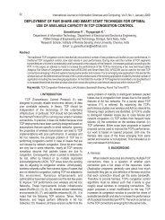
12 International Journal on Intelligent Electronic Systems, Vol.3, No.1, January 2009<br />
A B C<br />
Fig.1. Three-level Inverter<br />
The VSI states available in a three-level VSI are<br />
presented as shown in fig. 2. As it can be seen, there are 4<br />
different kinds of vectors depending on the module, Zero<br />
vectors (Vz), Large vectors (Vll, V21, V31, V41, V51, V61),<br />
Medium vectors (V1m, V2m, V3m, V4m, V5m, V6m) and<br />
Small vectors( V1s, V2s, V3s, V4s, V5s, V6s).<br />
Fig.2. Voltage vectors for three level inverter<br />
The state of the switches for each leg (C A, CBand C) c is shown in brackets (2: phase connected to the<br />
positive of the DC-link; 1: phase connected to the middle<br />
point of the DC-link (NP); 0: phase connected to the<br />
negative of the DC-link). The out-put voltage vector is<br />
defined by the following ex-pression:<br />
(1)<br />
VDC<br />
v ( 3C<br />
A bCB<br />
b<br />
Cc<br />
); CA,<br />
CB<br />
, Cc<br />
9<br />
where<br />
<br />
2<br />
j <br />
*<br />
{<br />
0,<br />
1,<br />
2}<br />
3<br />
2<br />
a e and b 2<br />
a a<br />
1<br />
.<br />
III. DTC PRINCIPLE<br />
In order to understand DTC principle some of the<br />
equations of the Induction Motor need to be reviewed. The<br />
electromagnetic torque can be ex-pressed as a function of<br />
the stator flux and the rotor flux space vectors as follows:<br />
e<br />
3 L<br />
P s r<br />
<br />
m<br />
2<br />
2 LsLr<br />
Lm<br />
(2)<br />
If the modulus of the previous expression is<br />
evaluated it is obtained :<br />
e<br />
3 Lm<br />
P sin ( ).<br />
2 r s s<br />
<br />
r<br />
2 L L L<br />
(3)<br />
s<br />
r<br />
m<br />
Considering the modulus of the rotor and stator fluxes<br />
constant, torque can be controlled by chang-ing the relative<br />
angle between both flux vectors. Stator flux can be adjusted<br />
by the stator voltage according to the stator voltage<br />
equation in stator fixed coordinates:<br />
ds<br />
us<br />
Rsis<br />
dt<br />
<br />
<br />
<br />
If the voltage drop in the stator resistance is<br />
neglected the variation of the stator flux is directly<br />
proportional to the stator voltage applied:<br />
d s<br />
u s <br />
dt<br />
<br />
<br />
<br />
s<br />
u s <br />
t<br />
<br />
<br />
<br />
Because the rotor time constant is larger than the stator<br />
one, the rotor flux changes slowly com-pared to the stator<br />
flux. Thus torque can be con-trolled by quickly varying the<br />
stator flux position by means of the stator voltage applied to<br />
the motor. The desired decoupled control of the stator flux<br />
modulus and torque is achieved by acting on the radial (x)<br />
and tangential (y) components respec-tively of the stator<br />
flux vector. According to (5) these two components will<br />
depend on the compo-nents of the stator voltage vector<br />
applied in the same directions. The tangential component<br />
of the stator voltage will affect the relative angle between<br />
the rotor and the stator flux vectors and in turns will control<br />
the torque variation according to (3). The radial component<br />
will affect the amplitude of the stator flux vector. There are<br />
two different loops corresponding to the magnitudes of the<br />
stator flux modulus and torque. The reference values for<br />
the stator flux modulus and the torque are compared with<br />
the estimated values, the resulting error values are fed into<br />
a standard VSI and a three-level hysteresis block<br />
respectively. The outputs of the stator flux error and torque<br />
error hysteresis blocks, together with the position of the<br />
stator flux are used as in-puts to the switching table (Table<br />
1). The position of the stator flux is divided into six different<br />
sectors. The output of the look-up table is the VSI state that<br />
will be applied during a sampling period. The stator flux<br />
modulus and torque errors tend to be restricted within its<br />
respective hysteresis bands. The principle of DTC<br />
(4)<br />
(5)