Download Full Paper - Sathyabama University
Download Full Paper - Sathyabama University
Download Full Paper - Sathyabama University

Create successful ePaper yourself
Turn your PDF publications into a flip-book with our unique Google optimized e-Paper software.
66 Journal on Intelligent Electronic Systems, Vol.1, No.1, November 2007<br />
Abstract<br />
Analytical Modeling of Nanoscale Double Gate FinFET Device<br />
Balwinder Raj, S. K.Vishvakarma, A. K. Saxena, S. Dasgupta<br />
Department of Electronics and Computer Engineering<br />
Indian Institute of Technology, Roorkee<br />
Roorkee - 247 667, INDIA E-mail : raj25dec@iitr.ernet.in<br />
FinFET is a novel double-gate device structure for future device design, modeling and circuit simulation purposes. FinFET have<br />
high-performance and low leakage, fully depleted silicon-on-insulator (FDSOI) device, which have been demonstrated down to<br />
15 nm gate length and are relatively simple to fabricate, which can be scaled to gate length below 10 nm. In this paper the<br />
modeling of potential and current is carried out. Further the theoretical aspects of the series resistance, reliability issues,<br />
process variation effects and device scaling limits are also described for this device.<br />
Key words : MOSFET, FinFET, Device Modeling, reliability issues<br />
I. INTRODUCTION<br />
The scaling of CMOS technology over the past<br />
several decades has resulted in continual improvements<br />
in integrated-circuit performance and cost per function.<br />
However, the scaling of conventional CMOS devices<br />
significantly beyond the 90-nm technology node will be<br />
challenging, due to limitations such as subthreshold<br />
leakage and gate-dielectric leakage [1]. To overcome<br />
some of the problems associated with planar CMOS<br />
device scaling, advanced MOSFET structures such as the<br />
double-gate FinFET device have been explored. These<br />
structures enable more aggressive device scaling<br />
because of their ability to control short-channel effects<br />
more effectively. Compared to a single-gate ultrathin-body<br />
device, the double-gate FinFET device is more electrostatically<br />
robust because two gates are used to control the<br />
channel, thus allowing for additional gate length scaling.<br />
Although double-gate transistors have been studied for<br />
quite some time, their adoption has been hindered by the<br />
complexity of their fabrication process [1, 5]. Recently,<br />
however, a more practical double-gate structure, the<br />
FinFET, was developed, with a process flow similar to that<br />
of conventional SOI CMOS processes [3]. According to<br />
Brew's scaling theory [4], the channel doping<br />
concentration in bulk MOSFETs should be continuously<br />
increased to suppress short-channel. Unfortunately, such<br />
a heavy doping concentration degrades device<br />
performance due to decreased mobility, increased<br />
junction capacitance, and increased junction leakage.<br />
Conventional bulk CMOS devices require aggressive gate<br />
oxide scaling, which increases the gate oxide leakage<br />
current, and ultra-shallow S/D (source/ drain) junctions to<br />
suppress short-channel effects. Alternative device<br />
structures are considered to circumvent these difficulties<br />
and continue to scale MOSFET gate lengths.<br />
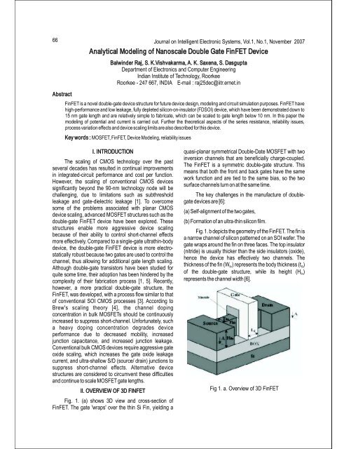
II. OVERVIEW OF 3D FINFET<br />
Fig. 1. (a) shows 3D view and cross-section of<br />
FinFET. The gate 'wraps' over the thin Si Fin, yielding a<br />
quasi-planar symmetrical Double-Date MOSFET with two<br />
inversion channels that are beneficially charge-coupled.<br />
The FinFET is a symmetric double-gate structure. This<br />
means that both the front and back gates have the same<br />
work function and are tied to the same bias, so the two<br />
surface channels turn on at the same time.<br />
The key challenges in the manufacture of doublegate<br />
devices are [6]:<br />
(a) Self-alignment of the two gates,<br />
(b) Formation of an ultra-thin silicon film.<br />
Fig.1. b depicts the geometry of the FinFET. The fin is<br />
a narrow channel of silicon patterned on an SOI wafer. The<br />
gate wraps around the fin on three faces. The top insulator<br />
(nitride) is usually thicker than the side insulators (oxide),<br />
hence the device has effectively two channels. The<br />
thickness of the fin (W ) represents the body thickness (t )<br />
fin Si<br />
of the double-gate structure, while its height (H )<br />
fin<br />
represents the channel width [6].<br />
Fig 1. a. Overview of 3D FinFET
Balwinder Raj et al : Analytical Modeling of Nanoscale Double Gate FinFET Device<br />
Fig. 1. b. Cross section of 2D FinFET<br />
Series resistance<br />
As the fin width is reduced, the parasitic series<br />
resistance in the source and drain increases. If the gate is<br />
misaligned to the source and drain pads, the output<br />
characteristics can be changed significantly. A selective<br />
Ge deposition process was proposed to alleviate the effect<br />
of misalignment and to reduce the series resistance [15].<br />
The use of Ge is attractive because it is a low temperature<br />
process, which is important for future integration with high-<br />
K gate dielectrics and metal gates. Furthermore, Ge<br />
provides an in-situ cleaning effect because GeH4 can<br />
remove native oxide. On-current was enhanced to 28%<br />
with selective Ge raised S/D process [15]. For further<br />
reduction of series resistance, metal germanide such as<br />
nickel-germanide can be attractive [2].<br />
Reliability<br />
It is timely to investigate reliability of FD-SOI CMOS<br />
FinFETs. For suppression of short-channel effects, the fin<br />
width is as narrow as possible. However, it can be a big<br />
concern that the extremely narrow fin width would be<br />
desirable in the device reliability point of view. Thus, DC<br />
hot-carrier tests were performed to evaluate device<br />
reliability for various device dimensions. In the thicker body<br />
case, hot electrons are more strongly driven towards the by<br />
the 2D curvature of the potential. Thus, hot-carrier<br />
immunity is improved by thinning the body of a double-gate<br />
MOSFET, which also improves short-channel effects [2],<br />
[9].<br />
Parameters<br />
A basic structure of FinFET is shown in Figure 2,<br />
which describes the different parameters used for the<br />
modeling. The critical geometrical parameters of FinFET<br />
are shown. Also the definition of these parameters<br />
described in the MOS control box as used in the setup of<br />
analytical and numerical modeling.<br />
67<br />
L : physical gate length of FinFET, H : height of silicon fin,<br />
gate fin<br />
defined by the distance between top gate and buried<br />
oxides, T : thickness of silicon fin, defined by the distance<br />
fin<br />
between front and back gate oxides, L : effective channel<br />
eff<br />
length of FinFET is estimated by the metallurgical junction<br />
for abrupt junctions, W: geometrical channel width defined<br />
as<br />
W=2*H fin +T fin.<br />
t oxf:<br />
oxide thickness of the front gate;<br />
t oxb:<br />
oxide thickness of the back gate;<br />
Fig. 2. Cross-sectional view of FinFET along the channel<br />
Length [7].<br />
When Tfin is much larger than Hfin or when top gate<br />
oxide is much thinner than the front and back oxides,<br />
FinFET can be approximately treated as single-gate fully<br />
depleted SOI MOSFET (FDFET) as long as the silicon fin<br />
remains fully depleted. On the other hand, when Hfin is<br />
much larger than Tfin or top gate oxide is much thicker than<br />
the front and back oxides, FinFET can be approximately<br />
treated as DGFET. The two limits of FinFET, FDFET and<br />
DGFET, are widely studied and well understood, but in the<br />
regime where both fin height and fin thickness have control<br />
over SCE, the dependence of SCE on device dimensions<br />
is not well characterized. In order to establish the functional<br />
expressions of potential, analytical solution of 3D Laplace<br />
equation is used to derive the design equations for the<br />
subthreshold behavior of FinFET. Based on the 3D<br />
electrostatic potential distribution in the subthreshold<br />
region, potential modeling is done [7].<br />
III. POTENTIAL MODELING<br />
Electrostatic Potential in sub-threshold region can be<br />
describe by 3D Laplace equation [13].
68<br />
∂ ψ ∂ ψ ∂ ψ<br />
∂x ∂y ∂z<br />
The six boundary conditions are set by the top gate,<br />
front gate, back gate, source, and drain and buried oxide<br />
Fig. 1. The buried oxide is assumed to be thick enough that<br />
any finite potential across the buried oxide leads to a<br />
negligible electric field. The boundaries between gate<br />
oxide and silicon fin are eliminated by replacing the<br />
physical dimensions with effective dimensions [8].<br />
Boundary conditions<br />
Top gate:<br />
ψ = V z H g −V<br />
= fb<br />
Bottom gate:<br />
ψ z=− H = V −V<br />
Front gate:<br />
Back gate:<br />
2 2 2<br />
+ 2 + 2 2 = 0<br />
Source side:<br />
fin<br />
fin<br />
fin<br />
g fb<br />
ψ = V −V<br />
x= T<br />
g fb<br />
ψ = V x 0 g −V<br />
= fb<br />
ψ φ<br />
y=<br />
0 ms =−<br />
Drain side:<br />
ψ =− φms<br />
+ V<br />
y= L<br />
ds (2.a)<br />
eff<br />
Here φmsis<br />
the work function difference of S/D to the<br />
channel, Vfb is the flat band voltage. Superposition<br />
principle can be applied to solve the 3-D linear Laplace's<br />
equation and the total potential is the sum of the potential<br />
at top gate, front gate, back gate, source and drain<br />
potential. The expression for the total potential at different<br />
boundaries is as follows [13], [15].<br />
ψ = ψtg + ψ fg + ψbg+ ψ s + ψ d (2.b)<br />
The potential expressions for the individual gate at<br />
different boundary conditions are given in Appendix A.<br />
The simulation results of potential with Vds and Vgs are<br />
shown in Fig. 3. and Fig. 4. respectively.<br />
IV. CURRENT MODELING<br />
In this section the current modeling of the Double-<br />
Gate FinFET Electrostatics is explained. The modeling of<br />
the top gate in the first order will just be an addition of a<br />
transistor, which is the same as a planar MOSFET, with the<br />
width of the Fin defining the width of the planar MOSFET.<br />
Thus for simplicity, we derive the current equations for a<br />
(1)<br />
Journal on Intelligent Electronic Systems, Vol.1, No.1, November 2007<br />
DG-FinFET as [10].<br />
I = µ W q<br />
ds eff fin I<br />
where<br />
Where qI is inversion layer charge, Vch is the quasi<br />
Fermi potential in the channel, µ eff is effective surface<br />
mobility and the current flows in the positive y direction,<br />
6<br />
Wfun is the width of FinFET, The value of vmax is 5x10 m/s<br />
[16]. The inversion charge in the channel can be<br />
expressed as,<br />
Where VG1 and VG2 are voltage applied at front and<br />
back gate respectively. An expression for current in term of<br />
charge is obtained as below [14]:<br />
(1 + qI / n1) dqI<br />
I (5)<br />
ds = µ effW<br />
dy<br />
Where<br />
µ<br />
eff<br />
dV<br />
dy<br />
ch<br />
µ s<br />
=<br />
⎛ V ⎞<br />
1+<br />
µ ⎜ ⎟<br />
ds<br />
S ⎜<br />
⎝vmaxLfff ⎟<br />
⎠<br />
⎛( VG1 + ( n1 −1) VG2 −VT)<br />
⎞<br />
qI = n1log[1+ exp⎜<br />
−Vch⎟<br />
⎝ n1<br />
⎠<br />
n<br />
1<br />
⎛ CC ⎞<br />
si ox2<br />
1 = +⎜ ⎟<br />
Cox1( Csi+ Cox2)<br />
⎝ ⎠<br />
(3)<br />
(4)<br />
After integrating eq (5) from source to drain, the drain<br />
current is given by<br />
2 2<br />
µ eff W ⎛qS − q<br />
⎞<br />
D<br />
Ids = ⎜ + ( qS−qD) ⎟<br />
L (6)<br />
eff ⎝ 2n1<br />
⎠<br />
Where qS and qD are the normalized charge at<br />
source and drain respectively. To get analytical solution of<br />
charge at source and drain replace the Vch with source and<br />
drain voltage respectively in equation of inversion charge<br />
[11], [14].<br />
⎛( VG1 + ( n1 −1) VG2 −VT)<br />
⎞<br />
qS = n1log[1 + exp⎜<br />
−VS<br />
⎟<br />
⎝ n1<br />
⎠<br />
⎛( VG1 + ( n1 −1) VG2 −V<br />
) ⎞<br />
T<br />
qD = n1log[1 + exp⎜<br />
−VDS<br />
⎟<br />
⎝ n1<br />
⎠<br />
V T is the threshold voltage, which is calculated from<br />
the following expression:<br />
⎛Csi + C ⎞ ox<br />
V 2 2<br />
(7)<br />
T = VFB+ φB<br />
+ qNAWfin ⎜ ⎟<br />
⎝ CC si ox ⎠
Balwinder Raj et al : Analytical Modeling of Nanoscale Double Gate FinFET Device<br />
⎛Csi + C ⎞ ox<br />
VT= 2VFB+ 2φB+<br />
qNAWfin ⎜ ⎟<br />
⎝ CC si ox ⎠<br />
In this equation VFB is the flat band voltage, φB<br />
is the<br />
Fermi potential, Wfun is the width of FinFET device.<br />
V. RESULTS<br />
In this paper the analytical modeling of potential and<br />
drain current for FinFET has been carried out for the device<br />
parameters Leff=60 nm, Heff =60 nm, Teff =20 nm,<br />
Vds=0.8 V, Vgs=0.2 V. Fig. 3 and Fig. 4 show the variation of<br />
potential with the distance along the channel length. at Vds<br />
= 0 V & 0.8 V respectively. Fig. 5 shows the variation of drain<br />
current with Vds, at Vgs=0.2 V. Fig. 6 shows the variation of<br />
Drain current with Vgs, at Vds=0.8 V.<br />
Fig. 3. Potential profile of FinFET at V =0V<br />
ds<br />
Fig. 4. Potential profile of FinFET at V =0.8V<br />
ds<br />
Fig. 5. Variation of drain current with V (V)<br />
ds<br />
Fig. 6. Variation of drain current with V (V)<br />
gs=<br />
VI. CONCLUSION<br />
69<br />
A FinFET is novel double-gate device structure<br />
demonstrated for sub-10nm device scaling. Key issues<br />
including FinFET device structure, Design parameters,<br />
potential modeling, current modeling, series resistance,<br />
reliability issues, process variation effects and device scaling<br />
limit are discussed. While a number of challenges remain to<br />
be overcome. Simulation results for potential profile of<br />
FinFET obtained along the channel distance at V =0 V & 0.8<br />
ds<br />
V. The drain current variation with V at 0.2 V gate voltage<br />
ds<br />
and with V at 0.8 V drain voltage is obtained for FinFET is<br />
gs<br />
similar to bulk MOSFET. The double-gate FinFET will lead<br />
the further device scaling. This model would be useful for the<br />
device as well as design engineers to fabricate the<br />
nanoscale FinFETs device and to simulate the circuits for<br />
circuit simulation purposes for future technology.
70<br />
Appendix a potential modeling<br />
⎛ kzπ<br />
⎞<br />
cosh ⎜ z ⎟<br />
∞ 16( Vg −V ) ⎛ fb (2m−1) π ⎞ ⎛(2n−1) π ⎞ ⎜ H ⎟<br />
eff<br />
ψ tg = sin y sin x<br />
⎝ ⎠<br />
∑<br />
2 ⎜ ⎟ ⎜ ⎟<br />
m= 1, n= 1 (2n−1)(2 m−1)<br />
π ⎜ L ⎟ ⎜<br />
eff T ⎟<br />
⎝ ⎠ ⎝ eff ⎠ cosh( kzπ)<br />
ψ<br />
ψ<br />
fg<br />
bg<br />
⎛kxπ⎞ sinh ⎜ x⎟<br />
∞<br />
n+<br />
1<br />
16( Vg −Vfb)( −1) ⎛(2m−1) π ⎞ ⎛(2n−1) π ⎞ ⎜ T ⎟<br />
eff<br />
= sin y cos z<br />
⎝ ⎠<br />
∑<br />
2 ⎜ ⎟ ⎜ ⎟<br />
m= 1, n= 1 (2n−1)(2m−1) π ⎜ L ⎟ ⎜<br />
eff 2H ⎟<br />
⎝ ⎠ ⎝ eff ⎠ sinh( kxπ)<br />
⎛kxπ⎞ sinh ⎜ ( T )<br />
1<br />
eff − x ⎟<br />
∞<br />
n+<br />
16( Vg −Vfb)( −1) ⎛(2m−1) π ⎞ ⎛(2n−1) π ⎞ ⎜ T ⎟<br />
eff<br />
= sin y cos z<br />
⎝ ⎠<br />
∑<br />
2 ⎜ ⎟ ⎜ ⎟<br />
m= 1, n= 1 (2n−1)(2m−1) π ⎜ L ⎟ ⎜<br />
eff 2H ⎟<br />
⎝ ⎠ ⎝ eff ⎠ sinh( kxπ)<br />
⎛kyπ⎞ sinh ⎜ ( L )<br />
1<br />
eff − y ⎟<br />
∞<br />
n+<br />
−16 φms ( −1) ⎛(2m−1) π ⎞ ⎛(2n−1) π ⎞ ⎜ L ⎟<br />
eff<br />
ψ s = sin x cos z<br />
⎝ ⎠<br />
∑<br />
2 ⎜ ⎟ ⎜ ⎟<br />
m= 1, n= 1 (2n−1)(2 m−1)<br />
π ⎜ T ⎟ ⎜<br />
eff 2H ⎟<br />
⎝ ⎠ ⎝ eff ⎠ sinh( kyπ)<br />
⎛kyπ⎞ sinh ⎜ y)<br />
⎟<br />
∞<br />
n+<br />
1<br />
−16( φms −Vds)( −1) ⎛(2m−1) π ⎞ ⎛(2n−1) π ⎞ ⎜ L ⎟<br />
eff<br />
ψ d = sin x cos z<br />
⎝ ⎠<br />
∑<br />
2 ⎜ ⎟ ⎜ ⎟<br />
m= 1, n= 1 (2n−1)(2 m−1)<br />
π ⎜ T ⎟ ⎜<br />
eff 2H ⎟<br />
⎝ ⎠ ⎝ eff ⎠ sinh( kyπ)<br />
2 2<br />
⎛2m−1⎞ ⎛2n−1⎞ k = ⎜ + × T<br />
⎜<br />
⎟<br />
L ⎟<br />
⎜<br />
⎟<br />
eff 2H<br />
⎟<br />
⎝ ⎠ ⎝ eff ⎠<br />
x eff<br />
2 2<br />
⎛2m−1⎞ ⎛2n−1⎞ k = ⎜ + × L<br />
⎜<br />
⎟<br />
T ⎟<br />
⎜<br />
⎟<br />
eff 2H<br />
⎟<br />
⎝ ⎠ ⎝ eff ⎠<br />
y eff<br />
2 2<br />
⎛2n−1⎞ ⎛2m−1⎞ k = ⎜ + × H<br />
⎜<br />
⎟<br />
T ⎟<br />
⎜<br />
⎟<br />
eff 2H<br />
⎟<br />
⎝ ⎠ ⎝ eff ⎠<br />
z eff<br />
ACKNOWLEDGMENT<br />
This research work is supported by Special<br />
Manpower Development Program in VLSI & Related<br />
Softwares Phase-II (SMDP-II), Ministry of Technology,<br />
Government of India under Project No. MIT-218-ECD.<br />
REFERENCES<br />
[0] Matthew Muh, “Design of a FinFET static frequency<br />
divider and a millimeter-wave CMOS push-push<br />
VCO” , Research Project, <strong>University</strong> of California at<br />
Berkeley.<br />
[1] Yang-Kyu Choi, MARCH, 2004. “FinFET for Terabit<br />
Era”, Journal of Semiconductor Technology and<br />
Science, Vol.4, No. 1,<br />
[2] Bing-Yue Tsui, and Chia-Pin Lin, Nov. 2005.<br />
”Process and Characteristics of Modified Schottky<br />
Barrier (MSB) p-Channel FinFET”, IEEE<br />
[3]<br />
Transactions on Electron Devices, Vol. 52, No. 11,<br />
J. Brews, W. Fichtner, E.H. Nicollian, S.M. Sze,<br />
1980. “Generalized Guide for MOSFET<br />
Miniaturization”, IEEE Electron Device Letters,<br />
Vol.1, P.2-4,<br />
Journal on Intelligent Electronic Systems, Vol.1, No.1, November 2007<br />
[4] X. Huang, W.-C. Lee, C. Kuo, D. Hisamoto, L.<br />
Chang, J. Kedzierski, E. Anderson, H. Takeuchi, Y.-<br />
K. Choi, K. Asano, V. Subramanian, T.-J. King, J.<br />
Bokor, C. Hu, 2001. “Sub-50 nm P-channel FinFET” ,<br />
IEEE Transactions On Electron Devices, VOL.48,<br />
P.880-886,<br />
[5] Weida Hu, Xiaoshuang Chen , Xuchang Zhou,<br />
Zhijue Quan, Lu Wei, 2006 “Quantum-Mechanical<br />
Effects and Gate Leakage Current of Nanoscale ntype<br />
FinFETs: A 2d Simulation Study”,<br />
[6]<br />
Microelectronics Journal, Elsevier, 37 613619.<br />
Dnyanesh S. Havaldar, Guruprasad Katti, Nandita<br />
DasGupta, and Amitava DasGupta, APRIL 2006.<br />
“Subthreshold Current Model of FinFETs Based on<br />
Analytical Solution of 3-D Poisson's Equation” IEEE<br />
Transactions On Electron Devices, Vol. 53, No. 4,<br />
[7] Guruprasad Katti, Nandita DasGupta, and Amitava<br />
DasGupta, JULY 2004. ” Threshold Voltage Model<br />
for Mesa-Isolated Small Geometry <strong>Full</strong>y Depleted<br />
SOI MOSFETs Based on Analytical Solution of 3-D<br />
Poisson's Equation”, IEEE Transactions On Electron<br />
Devices, Vol. 51, No. 7,<br />
[8] Digh Hisamoto, Wen-Chin Lee, Jakub Kedzierski,<br />
Hideki Takeuchi, Kazuya AsanoCharles Kuo, Erik<br />
Anderson, Tsu-Jae King, Jeffrey Bokor, and<br />
[9]<br />
Chenming Hu, DECEMBER 2000. “FinFET-A Self-<br />
Aligned Double-Gate MOSFET Scalable to 20 nm”,<br />
IEEE Transactions On Electron Devices, Vol. 47, No.<br />
12,<br />
Mohammed R.Rahman, MAY 2004. “Design and<br />
Fabrication of Tri-Gated FinFET”,22nd Annual<br />
Microelectronic Engineering Conference,<br />
[10] Bing-Yue Tsui, and Chia-Pin Lin, NOVEMBER 2005.<br />
”Process and Characteristics of Modified Schottky<br />
Barrier (MSB) p-Channel FinFET”, IEEE<br />
Transactions On Electron Devices, Vol. 52, No. 11,<br />
[11] H. S Philip Wong, “Beyond the conventional<br />
transistor” Science Direct, Solid-state Electronics 49<br />
(2005) 755762.<br />
[12] Gen Pei, Jakub Kedzierski, Phil Oldiges, Meikei<br />
Ieong, and Edwin Chih-Chuan Kan, AUGUST 2002.<br />
“FinFET Design Considerations Based on 3-D<br />
Simulation and Analytical Modeling” IEEE<br />
Transactions On Electron Devices, Vol. 49, No. 8,<br />
[13] Mansun Chan, Yuan Taur, Chung-Hsun Lin, Jin<br />
He,Ali M. Niknejad and Chenming Hu, “AFramework<br />
for Generic Physics Based Double-Gate Mosfet
Balwinder Raj et al : Analytical Modeling of Nanoscale Double Gate FinFET Device<br />
Modeling” <strong>University</strong> Of California At Berkeley,<br />
Berkeley, Ca 94720-1770.<br />
[14] G. Gildenblat, T.-L. Chen, X. Gu, H. Wang and X.<br />
Cai, “An Advanced Surface-Potential-Based<br />
Compact MOSFET Model (invited)”, IEEE 2003<br />
Custom Integrated Circuits Conference.<br />
71<br />
[15] Y.-K. Choi, N. Lindert, P. Xuan, S. Tang, D. Ha, E.<br />
Anderson, T.-J. King, J. Bokor, C. Hu, 2001. “Sub-<br />
20nm CMOS FinFET Technologies” , IEEE Iedm<br />
Technical Digest, P.421-424,<br />
[16] Sung-Mo Kang and Yusuf Leblebici,1999. “CMOS<br />
Digital Integrated Cicuits” , Second edition