Download Full Paper - Sathyabama University
Download Full Paper - Sathyabama University
Download Full Paper - Sathyabama University

You also want an ePaper? Increase the reach of your titles
YUMPU automatically turns print PDFs into web optimized ePapers that Google loves.
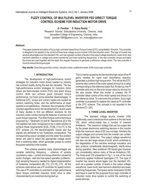
International Journal on Intelligent Electronic Systems, Vol.3, No.1, January 2009<br />
Abstract<br />
FUZZY CONTROL OF MULTILEVEL INVERTER FED DIRECT TORQUE<br />
CONTROL SCHEME FOR INDUCTION MOTOR DRIVE<br />
1 2<br />
G. Pandian S. Rama Reddy<br />
1<br />
Research Scholar, <strong>Sathyabama</strong> <strong>University</strong>, Chennai, India.<br />
2<br />
Jerusalem College of Engineering, Chennai, India.<br />
1 2<br />
Email : pandian1960@yahoo.co.in, srr_victory@yahoo.com<br />
This paper presents simulation of fuzzy logic controller based Direct Torque Control (DTC) using Matlab / Simulink. This controller<br />
is designed to be applied in the control of three-level voltage source inverter (VSI) fed induction motor. This type of inverter has<br />
several advantages over the standard VSI, such as a greater number of levels in the output voltage waveforms, lower dv/dt, less<br />
harmonic distortion in voltage and current waveforms and lower switching frequencies. In the new controller, torque and stator<br />
flux errors are used together with the stator flux angular frequency to generate a reference voltage vector. The new controller is<br />
found to reduce the torque ripple.<br />
Key words: Direct torque and flux control, induction motor, multilevel inverter, SVM, fuzzy logic controller.<br />
I. INTRODUCTION<br />
The development of high-performance control<br />
strategies for induction motor drives needed by industry<br />
has evolved rapidly during the last two decades. The two<br />
high-performance control strategies for induction motor<br />
drives are field-oriented control (FOC) and direct torque<br />
control. Both can achieve good transient torque<br />
performance, but have some essential disadvantages. In<br />
traditional DTC, torque and current ripples are caused by<br />
random switching times, and the performance at lower<br />
speeds is not satisfactory. However, the complexity of field<br />
oriented algorithms led to the development in recent years<br />
of many studies to find out different solutions for the<br />
induction motor control having the features of precise and<br />
quick torque response. The direct torque control technique<br />
proposed by I. Takahashi [1] and M. Depenbrock [2] in the<br />
mid eighties has been recognized to be a viable solution to<br />
achieve these requirements [l]-[3], [7]-[9], [11]-[17]. In the<br />
DTC scheme [1], the electromagnetic torque and flux<br />
signals are delivered to two hysteresis comparators. The<br />
corresponding output variables and the stator flux position<br />
sector are used to select the appropriate voltage vector<br />
from a switching table, which generates pulses to control<br />
the power switches in the inverter.<br />
This scheme presents many disadvantages are<br />
variable switching frequency - violence of polarity<br />
consistency rules – current and torque distortion caused by<br />
sector changes - start and low-speed operation problems -<br />
high sampling frequency needed for digital implementation<br />
of hysteresis comparators [8], [11], [13-15], [17]. All the<br />
schemes cited above use a PI controller for speed control.<br />
The use of PI controllers to command a high performance<br />
direct torque controlled induction motor drive is often<br />
characterised by an overshoot during start up.<br />
This is mainly caused by the fact that the high value of the PI<br />
gains needed for rapid load disturbance rejection<br />
generates a positive high torque error. This will let the DTC<br />
scheme take control of the motor speed driving it to a value<br />
corresponding to the reference stator flux.At start up, the PI<br />
controller acts only on the error torque value by driving it to<br />
the zero border. When this border is crossed, the PI<br />
controller takes control of the motor speed and drives it to<br />
the reference value. To overcome this problem, fuzzy logic<br />
controller is proposed to replace the classical PI controller<br />
in the DTC scheme. This concept is not reported in the<br />
literature [1] – [20].<br />
II. THREE LEVEL INVERTER<br />
The standard voltage source inverter (VSI)<br />
traditionally used in electrical drive systems is the two-level<br />
VSI, which unfortu-nately has a number of inherent<br />
limitations. The maximum voltage that can be suppor-ted<br />
by the power electronics switching devices in the inverter<br />
limits the maximum value of DC bus vol-tage. Similarly the<br />
output voltages and currents from the inverter can contain<br />
high harmonic distor-tion. The output voltage waveforms<br />
can also con-tain large values of dv/dt, which contribute to<br />
the degradation of the machine windings insulation and<br />
also produce considerable electromagnetic interfe-rence<br />
during operation. New multilevel VSI topolo-gies however<br />
can considerably reduce many of the-se limitations [16].<br />
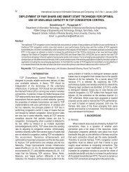
The three-level VSI presented in Fig.1, is one of the most<br />
commonly applied multilevel topologies [17]. This type of<br />
inverter has several advan-tages over the standard VSI,<br />
such as a greater number of levels in the output voltage<br />
waveforms, lower dv/dt, less harmonic distortion and lower<br />
switching frequencies. The space vector modulation (SVM)<br />
technique is used for the proposed fuzzy logic controller of<br />
induction motor drive system to control the switching of<br />
power devices.<br />
11
12 International Journal on Intelligent Electronic Systems, Vol.3, No.1, January 2009<br />
A B C<br />
Fig.1. Three-level Inverter<br />
The VSI states available in a three-level VSI are<br />
presented as shown in fig. 2. As it can be seen, there are 4<br />
different kinds of vectors depending on the module, Zero<br />
vectors (Vz), Large vectors (Vll, V21, V31, V41, V51, V61),<br />
Medium vectors (V1m, V2m, V3m, V4m, V5m, V6m) and<br />
Small vectors( V1s, V2s, V3s, V4s, V5s, V6s).<br />
Fig.2. Voltage vectors for three level inverter<br />
The state of the switches for each leg (C A, CBand C) c is shown in brackets (2: phase connected to the<br />
positive of the DC-link; 1: phase connected to the middle<br />
point of the DC-link (NP); 0: phase connected to the<br />
negative of the DC-link). The out-put voltage vector is<br />
defined by the following ex-pression:<br />
(1)<br />
VDC<br />
v ( 3C<br />
A bCB<br />
b<br />
Cc<br />
); CA,<br />
CB<br />
, Cc<br />
9<br />
where<br />
<br />
2<br />
j <br />
*<br />
{<br />
0,<br />
1,<br />
2}<br />
3<br />
2<br />
a e and b 2<br />
a a<br />
1<br />
.<br />
III. DTC PRINCIPLE<br />
In order to understand DTC principle some of the<br />
equations of the Induction Motor need to be reviewed. The<br />
electromagnetic torque can be ex-pressed as a function of<br />
the stator flux and the rotor flux space vectors as follows:<br />
e<br />
3 L<br />
P s r<br />
<br />
m<br />
2<br />
2 LsLr<br />
Lm<br />
(2)<br />
If the modulus of the previous expression is<br />
evaluated it is obtained :<br />
e<br />
3 Lm<br />
P sin ( ).<br />
2 r s s<br />
<br />
r<br />
2 L L L<br />
(3)<br />
s<br />
r<br />
m<br />
Considering the modulus of the rotor and stator fluxes<br />
constant, torque can be controlled by chang-ing the relative<br />
angle between both flux vectors. Stator flux can be adjusted<br />
by the stator voltage according to the stator voltage<br />
equation in stator fixed coordinates:<br />
ds<br />
us<br />
Rsis<br />
dt<br />
<br />
<br />
<br />
If the voltage drop in the stator resistance is<br />
neglected the variation of the stator flux is directly<br />
proportional to the stator voltage applied:<br />
d s<br />
u s <br />
dt<br />
<br />
<br />
<br />
s<br />
u s <br />
t<br />
<br />
<br />
<br />
Because the rotor time constant is larger than the stator<br />
one, the rotor flux changes slowly com-pared to the stator<br />
flux. Thus torque can be con-trolled by quickly varying the<br />
stator flux position by means of the stator voltage applied to<br />
the motor. The desired decoupled control of the stator flux<br />
modulus and torque is achieved by acting on the radial (x)<br />
and tangential (y) components respec-tively of the stator<br />
flux vector. According to (5) these two components will<br />
depend on the compo-nents of the stator voltage vector<br />
applied in the same directions. The tangential component<br />
of the stator voltage will affect the relative angle between<br />
the rotor and the stator flux vectors and in turns will control<br />
the torque variation according to (3). The radial component<br />
will affect the amplitude of the stator flux vector. There are<br />
two different loops corresponding to the magnitudes of the<br />
stator flux modulus and torque. The reference values for<br />
the stator flux modulus and the torque are compared with<br />
the estimated values, the resulting error values are fed into<br />
a standard VSI and a three-level hysteresis block<br />
respectively. The outputs of the stator flux error and torque<br />
error hysteresis blocks, together with the position of the<br />
stator flux are used as in-puts to the switching table (Table<br />
1). The position of the stator flux is divided into six different<br />
sectors. The output of the look-up table is the VSI state that<br />
will be applied during a sampling period. The stator flux<br />
modulus and torque errors tend to be restricted within its<br />
respective hysteresis bands. The principle of DTC<br />
(4)<br />
(5)
Pandian et al : Fuzzy Control of Multilevel Inverter Fed Direct Torque...<br />
operation can also be ex-plained by analyzing the Induction<br />
Motor stator voltage equation in the stator flux reference<br />
frame.<br />
<br />
d<br />
s <br />
us R<br />
sis<br />
j<br />
s<br />
s<br />
dt<br />
(6)<br />
If this expression is separated into de direct (x) and the<br />
quadrature component (y) of the stator voltage, the<br />
following expressions are can be ob-tained:<br />
u<br />
sx<br />
dsx<br />
R<br />
sisx<br />
<br />
dt<br />
usy R<br />
sisy<br />
s<br />
sx<br />
(8)<br />
In the same reference frame fixed to the stator flux vector<br />
the electromagnetic torque can be ex-pressed as:<br />
e<br />
e<br />
P s is<br />
<br />
3 <br />
<br />
2<br />
(7)<br />
(9)<br />
3<br />
3<br />
P ( sx isy<br />
<br />
syisx<br />
) P<br />
sx<br />
isy<br />
2<br />
2<br />
(10)<br />
<br />
Combining expression (8) with (10) the following torque<br />
expression is obtained:<br />
e<br />
3 <br />
sx ( usy<br />
s<br />
sx )<br />
P<br />
2 R<br />
(11)<br />
From expression (7) it can be concluded that sta-tor flux<br />
amplitude can be controlled by means of the direct<br />
component of the stator volta-ge. It is also evident from<br />
equation (11) that the electromagnetic torque can be<br />
controlled by means of the quadrature component of the<br />
stator voltage, under adequate decoupling of the stator flux.<br />
From equation (11) some other conside-rations can be<br />
made as torque depends on the stator flux amplitude as<br />
well and it also depends on the stator flux angular speed,<br />
which depends on the operating point of the machine. DTC<br />
requires the estimation of stator flux and torque, which can<br />
be performed by means of two different phase currents, the<br />
state of the VSI and the voltage level in the DC-link. This<br />
estimation is based in the stator voltage equation [3].<br />
<br />
Table.1<br />
<br />
dt i R u s ( s s s )<br />
<br />
<br />
<br />
s<br />
(12)<br />
K(Ys) 1 2 3 4 5 6<br />
d = 1<br />
d = - 1<br />
d= 1 V2<br />
d = Q V7<br />
d = - l V6<br />
d= l V3<br />
In order to show the effect of fuzzy logic controller on DTC<br />
motor drive performances, simulation have been<br />
performed using the DTC induction motor drive structure<br />
illustrated by Fig.3, where the controller block is first<br />
replaced by a classical PI controller and then by a fuzzy<br />
logic controller. The parameters of the motor used in the<br />
simulation are given in Table 2. The reference speed used<br />
is W = 1420 rpm.<br />
ref<br />
Fig. 3 Block diagram of fuzzy logic controlled drive<br />
Table 2. Induction machine Parameters<br />
IV. FUZZY LOGIC CONTROLLER<br />
During the past several years, fuzzy logic control<br />
technology has been widely and successfully utilized in<br />
numerous industrial applications and consumer products.<br />
Since fuzzy logic with human like but systematic property<br />
can convert the linguistic control rules based on expert<br />
V<br />
3<br />
V<br />
0<br />
V<br />
1<br />
V<br />
4<br />
d= 0 V0<br />
V<br />
7<br />
d = - l V5 V<br />
6<br />
V4 V5 V6 V1<br />
V7 V0 V7 V0<br />
V2 V3 V4 V5<br />
V5 V6 V1 V2<br />
V0 V7 V0 V7<br />
V1 V2 V3 V4<br />
No of poles .4, 50<br />
HZ<br />
2HP, 400V, 1420rpm<br />
Rs = 4.85ohm, Rr= 3.805ohm,<br />
Ls=274 mH Lr=274 mH<br />
Lm=258 mH J=0.031 kg sq.m<br />
13
14 International Journal on Intelligent Electronic Systems, Vol.3, No.1, January 2009<br />
knowledge into automatic control strategy, it can be well<br />
applied to control the systems with un-modeled dynamics<br />
[7, 8]. On the basis of these properties of fuzzy logic, this<br />
paper proposes an adaptive fuzzy logic concept to improve<br />
the performances of existing DTC drive systems. The main<br />
advantage of using fuzzy logic control structure is that one<br />
does not have to redesign the existed control system but<br />
also acquire the satisfactory response when disturbances<br />
and noises enter.<br />
V. SIMULATION RESULTS<br />
The simulation results of the adaptive fuzzy logic<br />
controller and classical PI controller based three level VSI<br />
fed DTC scheme for induction motor drive are presented<br />
and compared. The inverter voltage and stator current<br />
waveforms of classical PI controller are shown in Figs. 4 &<br />
5. The speed & torque curves are shown in Fig. 6. The<br />
inverter voltage and stator current waveforms of the<br />
adaptive fuzzy controller are shown in Figs. 7 & 8. The<br />
speed & torque performance are shown in Fig. 9.<br />
Fig. 4 Inverter voltage waveform<br />
Fig. 5 Stator current waveform<br />
Fig. 6 Motor speed and torque waveform<br />
Fig. 7 Inverter voltage waveform<br />
Fig. 8 Stator current waveform<br />
Fig. 9 Motor speed and torque waveform<br />
VI. CONCLUSION<br />
The fuzzy logic controller and classical PI controller based<br />
three level VSI fed DTC scheme for induction motor drives<br />
are simulated and the simulation results are presented. The<br />
performance with the fuzzy logic controller is better than<br />
that of PI controller based DTC scheme. The torque ripple<br />
is reduced in the fuzzy controller based system. There is a<br />
considerable reduction of harmonic distortion in stator<br />
current by using three level inverter.<br />
REFERENCES<br />
[1] Takahashi, T. Noguchi, Sept./Oct. 1986 “A new quick<br />
response and high efficiency control strategy of an<br />
induction motor,” IEEE Trans. Ind. Applicat., vol. IA-<br />
22, pp. 820.827,.<br />
[2] M. Depenbrok,Oct. 1988 “Direct self-control (DSC) of<br />
inverter fed induction machine,” IEEE Trans. Power<br />
Electron., vol. PE-3, pp. 420.429 .
Pandian et al : Fuzzy Control of Multilevel Inverter Fed Direct Torque...<br />
[3] T. G. Hableter, F. Profumo, M. Pastorelli, L. M.<br />
Tolbert,Sept./Oct. 1992. 48 “Direct torque control of<br />
induction machines using space vector modulation,”<br />
IEEE Trans. Ind.Applicat., vol. 28, pp. 1045.1053.<br />
[4] I. Boldea, S. A. Nasar,1988 “Torque vector control<br />
(TVC).A class of fast and robust torque speed and<br />
position digital controller for electric drives,” in Proc.<br />
EMPS, vol. 15, , pp. 135.148.<br />
[5] J.-S. R. Jang,Sept.1992 “Self-learning fuzzy<br />
[6]<br />
controllers based on temporal back propagation,”<br />
IEEE Trans. Neural Networks, vol. 3, pp. 714.723 .<br />
J.-S. R. Jang, May/June 1993 “ANFIS: Adaptivenetwork-based<br />
fuzzy inference system,” IEEE Trans.<br />
Syst., Man, Cybern., vol. 23, pp. 665.684.<br />
[7] D. Casadei, G. Grandi, G. Serra,Sept. 8.10, 1993<br />
“Study and implementation of a simplied and efficient<br />
digital vector controller for induction motors,” in Proc.<br />
EMD’9 3, Oxford, U.K , pp. 196.201.<br />
[8] M. P. Kazmierko wski, H. Tunia,1994, Automatic<br />
Control of Converter-Fed Drives. Amsterdam, The<br />
Netherlands: Elsevier.<br />
[9] P. Tiitinen, P. Pohkalainen, J. Lalu,Mar.1995, “The<br />
next generation motor control method: Direct torque<br />
control (DTC),” EPE J., vol. 5, pp. 14.18..<br />
[10] J.-S. R. Jang, C.-T. Sun, Mar.1995, “Neuro-fuzzy<br />
modeling and control,” Proc. IEEE, vol. 83, pp.<br />
378.406.<br />
[11] M. P. Kazmierkowski, A. Kasprowicz, Aug. 1995<br />
“Improved direct torque and flux vector control of<br />
PWM inverter-fed induction motor drives,” IEEE<br />
Trans. Ind. Electron, vol. 45, pp. 344.350.<br />
[12] J. N. Nash, Mar./Apr.1997, “Direct torque control,<br />
induction motor vector control without an encoder,”<br />
IEEE Trans. Ind.Applicat., vol. 33, pp. 333.341.<br />
[13] A. Damiano, P. Vas et al.,1997,“Comparison of<br />
speed-sensorless DTC induction motor drives,” in<br />
Proc. PCI M, Nuremberg, Germany, pp. 1.11.<br />
[14] G. Buja, Dec.1998.“A new control strategy of the<br />
induction motor drives: The direct .ux and torque<br />
control,” IEEE Ind. Electron. Soc. Newslett., vol. 45,<br />
pp. 14.16.<br />
[15] P. Vas,1998, Sensor less Vector and Direct Torque<br />
Control. Oxford, U.K.: Oxford Univ. Press .<br />
[16] D. Casadei, G. Serra, A. Tani, “ Implementation of a<br />
Direct Torque Control Algorithm for Induction Motors<br />
based on Discrete Space Vector Modulation” IEEE<br />
Trans. Power Electron., Vol. 15, N. 4, pp. 769-777,<br />
July 2000.<br />
[17] P. Z. Grabowski, M. P. Kazmierkowski, B. K. Bose, F.<br />
Blaabjerg, “A Simple Direct Torque Neuro Fuzzy<br />
Control of PWM Inverter Fed Induction Motor Drive”<br />
IEEE Trans. Ind. Electron., Vol. 47, No. 4, pp. 863-<br />
870,August 2000.<br />
[18] A. Miloudi and A. Draou, Nov 2002, “Variable Gain PI<br />
Controller Design For Speed Control and Rotor<br />
Resistance Estimation of an Indirect Vector<br />
[19]<br />
Controlled Induction Machine Drive “ Conference<br />
Record of the IECON ¡¯02 Sevilla, Spain, Vol. 1, pp.<br />
323-328..<br />
A. Miloudi, E. A. Al Radadi, A. Draou, Y. Miloud, 20 .<br />
25 June 2004.“ Simulation and Modelling of a<br />
Variable Gain PI Controller For Speed Control of a<br />
Direct Torque Neuro Fuzzy Controlled Induction<br />
Machine Drive “, Conf. Rec. PESC’04, Aachen,<br />
Germany.<br />
[20] A. Miloudi, E. A. Alradadi, A. Draou,13 July 2006 “ A<br />
new control strategy of direct torque fuzzy control of a<br />
PWM inverter fed induction motor drive “, Conf. Rec.<br />
ISIE2006, Montreal, Canada, 09 .<br />
G. Pandianreceived the B.E degree<br />
in Electrical & Electronics<br />
Engineering from College of<br />
Engineering Anna <strong>University</strong><br />
Chennai India in 1994 and MS<br />
degree in Electronics & Control from<br />
Birla Institute of Technology and<br />
Science Pilani India in 1998. He is<br />
currently pursuing Ph.D degree in<br />
<strong>Sathyabama</strong> <strong>University</strong> Chennai India and his<br />
research area is vector control of induction motor<br />
drives. He was working in Electrical Engineering<br />
Dept. Dunlop India Ltd Chennai India. He is fellow of<br />
Institution of Electronics and Telecommunication<br />
Engineers India, Member of Institution of Engineers<br />
(India), Member of Institution of Engineering and<br />
Technology London, Member of IEEE.<br />
15