Patchmaster - HEKA Elektronik Dr. Schulze GmbH
Patchmaster - HEKA Elektronik Dr. Schulze GmbH
Patchmaster - HEKA Elektronik Dr. Schulze GmbH

Create successful ePaper yourself
Turn your PDF publications into a flip-book with our unique Google optimized e-Paper software.
Electrophysiology Electrochemistry<br />
If you believe your job is to<br />
make new discoveries....<br />
PATCHMASTER<br />
Multi-channel data acquisition software<br />
discover the software<br />
PATCHMASTER:<br />
• operates on Windows and<br />
Macintosh platforms<br />
• full software control of <strong>HEKA</strong><br />
patch clamp amplifiers<br />
• calibrates and tests the patch<br />
clamp amplifiers of the<br />
EPC 9 and EPC 10 series<br />
• featuring new concepts of<br />
adaptive feedback control<br />
and global variables<br />
• suitable for research and<br />
industry<br />
....featuring....<br />
• digital oscilloscope<br />
• versatile waveform<br />
generator<br />
• multi-channel stimulation<br />
and data acquisition<br />
• control of external devices<br />
• powerful online analysis<br />
• experiment automation and<br />
standardization<br />
• macro programming<br />
• data tree editor<br />
• full data integrity due to<br />
parameter storage<br />
...including...<br />
• software Lock In amplifier for<br />
capacitance measurements<br />
in whole-cell and on-cell<br />
<strong>HEKA</strong> provides the finest instruments today to achieve the needed progress of tomorrow…<br />
mode<br />
• Photometry extension to<br />
control light sources and<br />
analysis of fluorescence<br />
measurements<br />
• Batch Control for platform<br />
independent control of<br />
PATCHMASTER from other<br />
software packages
PATCHMASTER goes beyond<br />
the limits of conventional patch<br />
clamp software.<br />
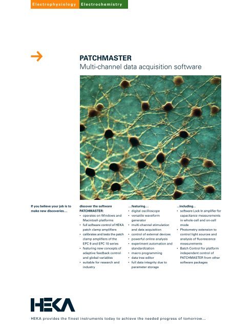
Picture front page:<br />
Network of horizontal cells in the retina.<br />
Courtesy of Max-Planck-Institute for Brain<br />
Research, Frankfurt.<br />
PATCHMASTER<br />
Multi-channel data acquisition software<br />
PatchMaster sets new<br />
standards in electrophysio-<br />
logical software<br />
PATCHMASTER offers features<br />
meeting the highest standards of<br />
modern electrophysiology. This<br />
new software, running on PC-<br />
based and Macintosh computers,<br />
harbors all the comfortable<br />
functions of PULSE, but offers a<br />
variety of novel procedures aimed<br />
to make electrophysiological<br />
research even more versatile and<br />
efficient. With PATCHMASTER,<br />
experimental design,<br />
performance, and analysis<br />
become much more flexible,<br />
giving rise to a high degree of<br />
automation and providing access<br />
to experimental protocols that<br />
were thus far unattainable with<br />
commercial software.<br />
Major innovations of the<br />
PATCHMASTER program<br />
More channels<br />
PATCHMASTER provides up to<br />
8(16) A/D input channels and 4(8)<br />
D/A stimulation channels that can<br />
be sampled at high speed. In<br />
addition, the number of channels<br />
is no longer limited to the number<br />
of available AD/DA channels.<br />
Virtual traces<br />
Acquired data traces can be<br />
processed online by mathe-<br />
matical functions to compile<br />
additional derived data traces.<br />
Extended trigger possibilities<br />
Up to 16 trigger outputs can be<br />
defined like a stimulation channel.<br />
Individual timing for different<br />
channels<br />
Channels can have completely<br />
independent timing and pulse<br />
patterns. This allows easy setup<br />
of complex stimulation patterns<br />
for multiple channels.<br />
Data compression<br />
For all channels, individual data<br />
compression factors can be<br />
specified to reduce the amount<br />
of stored data.<br />
Global parameters for sequence<br />
editing<br />
For definition of a pulse generator<br />
sequence, global parameters can<br />
be used, e.g. to define the<br />
duration of a segment or the<br />
amplitude of a stimulation. If<br />
these parameters are used in<br />
multiple segments or sequences,<br />
all locations can be edited by<br />
changing a single global<br />
parameter.<br />
Multiple Telegraphing Amplifiers<br />
More than one telegraphing<br />
amplifier can be supported by<br />
using multiple lookup tables.<br />
Extended Lock-In<br />
Simultaneous capacitance<br />
measurements on multiple<br />
headstages of a patch clamp<br />
amplifier (EPC 10 Double, Triple,<br />
and Quadro) and On-Cell<br />
capacitance measurements at<br />
high sine wave frequencies are<br />
now possible.<br />
Extended Online Analysis<br />
An arbitrary number of online<br />
functions and methods can be<br />
defined and saved. Even complex<br />
calculations are now possible.<br />
Online analysis methods can be<br />
directly linked to acquisition<br />
sequences.<br />
Two Online Analysis windows<br />
Up to 12 graphs can be displayed<br />
in two different Online Analysis<br />
windows. For example, one<br />
window can be used to display<br />
series derived analyses such as<br />
IVs, and the other for display of<br />
time lapse data.<br />
Photometry feature<br />
Multi-wavelength stimulation for<br />
multiple fluorescence excitation<br />
systems and analysis for multiple<br />
fluorescence signals is now<br />
supported.<br />
Protocol Editor for automation<br />
A complete experiment can be<br />
automated and standardized,<br />
including incorporation of<br />
feedback from online analysis or<br />
external devices.<br />
PATCHMASTER – a program<br />
for patch clamp, 2-electrode<br />
voltage clamp experiments,<br />
and general data acquisition<br />
Full support of <strong>HEKA</strong>’s patch<br />
clamp amplifiers EPC 7, EPC 8,<br />
EPC 9, and the EPC 10. The novel<br />
program design of PATCH-<br />
MASTER is perfectly suited for<br />
the operation of multi-channel<br />
stimulation as used for patch<br />
clamp amplifiers with multiple<br />
headstages (e.g. EPC 9 Double /<br />
Triple, EPC 10 Double / Triple /<br />
Quadro).<br />
Additionally, PATCHMASTER can<br />
be run with any other patch clamp<br />
amplifier, electrophysiological<br />
current clamp or voltage clamp<br />
devices (e.g. two-electrode<br />
voltage clamps used for research<br />
on Xenopus oocytes) or a stand-<br />
alone data acquisition interface<br />
for general stimulation/data<br />
acquisition purposes.
Display<br />
Change the display of the<br />
oscilloscope (e.g. grid, dimmed<br />
overlay).<br />
Replay<br />
Export your data (e.g. single<br />
sweep, online analysis results) to<br />
printer, Matlab, IgorPro ® files or<br />
ASCII (MAC or WINDOWS).<br />
Replay Window<br />
Acquired data and previous<br />
recorded data files can be<br />
reviewed and edited. Data files<br />
acquired with PULSE are<br />
automatically converted to the<br />
PATCHMASTER file format.<br />
Online Analysis<br />
Immediate analysis of the just<br />
acquired or replayed data. The<br />
analysis result is shown as a<br />
function of a variety of<br />
parameters, specified by the<br />
user.<br />
PATCHMASTER<br />
A powerful software for acquisition and analysis of electrophysiological data<br />
Buffer<br />
Add, subtract or accumulate<br />
your measured traces.<br />
Macros<br />
Macro features allow the<br />
recording of routine functions<br />
and then accessing these<br />
Macros by a simple mouse click<br />
or key stroke.<br />
Notebook<br />
During stimulation and replay,<br />
the results of the online analysis<br />
are displayed in the notebook.<br />
These data columns can be<br />
exported to disk or copied to<br />
the clipboard.<br />
Oscilloscope<br />
Digital oscilloscope with<br />
zoom, digital filters, and<br />
overlay. The size of the<br />
window can be customized.<br />
Protocol Editor<br />
With the Protocol Editor, complex<br />
experimental procedures can be<br />
designed, stored, and executed.
Control Selection<br />
Three different window sizes can be set by a<br />
mouse click to show different sets of control<br />
buttons.<br />
Macros<br />
Macro features allow the recording of routine<br />
functions and then accessing these Macros by<br />
a simple mouse click.<br />
Test Pulse<br />
There are two test pulse modes: built-in test<br />
pulses (double or single) and use of a stimulation<br />
template from the pulse generator as test pulse.<br />
Capacitance Compensations<br />
Automatic routines for leak and capacitive<br />
transient compensations, perform these tasks<br />
faster and more accurate than even the most<br />
experienced experimenter. Capacitance tracking<br />
allows continuous updating of membrane<br />
capacitance and series resistance compensation<br />
during recording sessions.<br />
Sequence Pool<br />
It is a paging bar with a nearly unlimited number<br />
of sequences. Loads, saves, copies etc. the pool<br />
of available stimulation sequences.<br />
Timing<br />
Determines the<br />
number of<br />
sweeps and the<br />
sweep and<br />
sample intervals.<br />
DA-channels<br />
Multiple DA<br />
channels and<br />
digital trigger lines<br />
can be addressed<br />
for output.<br />
Segments<br />
A pulse pattern<br />
consists of an<br />
arbitrary number<br />
of segments.<br />
Template Preview<br />
The stimulation<br />
template is also<br />
shown graphically.<br />
pgf-Parameters<br />
Segment parameters are assignable by<br />
global variables.<br />
PATCHMASTER<br />
The virtual front panel of EPC 10 patch clamp amplifier<br />
Monitoring<br />
Gain and holding parameters can be set. The<br />
measured current and voltage as well as the<br />
resulting membrane resistance (if applicable) is<br />
always displayed.<br />
Offset Compensation<br />
A liquid junction potential can be specified.<br />
The offset potential can be cancelled out<br />
automatically. The Track function allows<br />
repetitive automatic cancellation of the offset<br />
potential.<br />
Leak and Rs Compensation<br />
This controls a hardware leak compensation. The<br />
series resistance compensation corrects for<br />
membrane voltage errors under conditions of high<br />
access resistance between pipette and cell interior.<br />
Filters<br />
Two built-in high-quality hardware filters<br />
(Butterworth/Bessel) perform excellent signal<br />
conditioning and remove the expense of<br />
purchasing additional filter instruments.<br />
Flexible Pulse Generator configures stimulation and acquisition<br />
Leak<br />
Determines various parameters of the leak<br />
pulses for p/n subtraction.<br />
Sweep Length<br />
The length of the stimulus<br />
and the amount of acquired<br />
data is displayed.<br />
AD Channels<br />
Multiple AD channels can be<br />
acquired simultaneously and<br />
processed (virtual trace). Data<br />
compression and store/non-<br />
store flags on individual traces<br />
reduces the required data<br />
storage capacity.<br />
Filter Factor<br />
The input filter is set<br />
automatically with respect<br />
to the sampling rate.<br />
Analysis<br />
Direct link of the stimulation<br />
template to the correspond-<br />
ing analysis method.<br />
Break Condition<br />
Break conditions can be<br />
defined for each AD channel.
The protocol editor is a com-<br />
pletely new feature of PATCH-<br />
MASTER. With this editor,<br />
complex experimental proce-<br />
dures can be designed, stored,<br />
and executed. This tool greatly<br />
increases the versatility of<br />
PATCHMASTER and provides<br />
means for automatic experiment<br />
performance.<br />
The principal idea of the protocol<br />
editor is to generate a list of<br />
events or tasks, which then are<br />
executed automatically. Various<br />
functions such as REPEAT<br />
LOOPs, input queries, or<br />
conditional statements allow for<br />
the generation of complex<br />
interactive processes.<br />
An arbitrary number of analyses<br />
can be performed on newly<br />
acquired or replayed data. Directly<br />
analyzed data or derivative data,<br />
obtained by application of<br />
mathematical functions on the<br />
analysis results, are then<br />
displayed in a versatile manner<br />
in several graphs placed in two<br />
independent windows. This<br />
allows for separation of different<br />
data types, for example, current-<br />
voltage plots are shown<br />
separately from time-based data<br />
(e.g. chart recording).<br />
Analysis templates can be<br />
predefined and stored. Thus,<br />
several analysis procedures are<br />
available such that various<br />
incoming data types can be<br />
analyzed without extra editing<br />
just by switching between<br />
analysis procedures. A direct link<br />
between Pulse Generator<br />
sequences and analysis<br />
procedures provides<br />
definition of data acquisition and<br />
analysis prior to the experiment.<br />
PATCHMASTER<br />
Online Analysis - Powerful on- and offline data processing<br />
Protocol Editor - Tool for automation and standardization of experiments<br />
The features offered by the protocol editor will be appreciated by scientists asking for complex, precisely<br />
timed experimental protocols. In addition, the high degree of automation possibilities increases efficiency,<br />
minimizes experimental errors and is thus suited for industrial applications.
The PATCHMASTER software,<br />
combined with our EPC 9 and<br />
EPC 10 patch clamp amplifiers<br />
provide you with everything you<br />
need for time-resolved measure-<br />
ment of membrane capacitance<br />
(Cm).<br />
The EPC 9 or EPC 10 is the ideal<br />
patch clamp for Cm measure-<br />
ments since all the relevant<br />
parameters are under control of<br />
PATCHMASTER. No additional<br />
hardware such as Lock In<br />
amplifiers and filters are required.<br />
PATCHMASTER<br />
Software Lock-In amplifier for capacitance measurements<br />
Implemented Lock In modes<br />
In 1982 Neher and Marty<br />
introduced the Lock In amplifier<br />
into the patch clamp field for Cm<br />
measurements using a single<br />
sine wave frequency. For<br />
determining the appropriate<br />
phase setting, they used dithering<br />
or the compensation network<br />
while changing the phase for<br />
obtaining a maximum signal for<br />
Cm. This method is appropriate<br />
under stationary conditions for<br />
measurements of changes in Cm.<br />
We refer to this method as the<br />
“piecewise-linear” method.<br />
Since the piecewise-linear<br />
method is prone to errors (see<br />
Gillis in B.Sakmann & E.Neher<br />
Eds. Single Channel Recording<br />
2nd Edition, Plenum Press)<br />
Lindau and Neher introduced in<br />
1988 a method using the real and<br />
imaginary part of the admittance<br />
plus the DC-conductance to<br />
determine the absolute values of<br />
Cm, membrane conductance,<br />
and access resistance. We refer<br />
to this method as the “Sine+DC”<br />
method.<br />
The best resolution of small<br />
changes in Cm are achieved in<br />
the cell-attached patch clamp<br />
configuration. Since a different<br />
equivalent circuit applies in this<br />
recording mode, a third method,<br />
referred to as the “On-Cell”<br />
method, has been implemented.<br />
Different modes of calibration<br />
Digital control of the filter<br />
settings, gain and compensation<br />
networks that are featured with<br />
the EPC 9 and EPC 10 patch<br />
clamp amplifiers directly benefit<br />
the Calculated calibration mode.<br />
Phase shifts introduced by the<br />
measuring system can be<br />
calculated and the corrected<br />
phase of the Lock In amplifier,<br />
which is dependent upon the<br />
recording conditions, can be set<br />
automatically.<br />
A Measured calibration method<br />
allows the phase and attenuation<br />
of the recording system to be<br />
determined by analysis of the<br />
admittance of a pure resistor at<br />
the amplifiers input.<br />
In case other procedures for<br />
determination of the phase and<br />
attenuation of the measuring<br />
system are used, a Manual<br />
calibration mode allows the<br />
phase and attenuation of the<br />
software Lock In to be directly<br />
set by the user.<br />
Lowest noise recordings<br />
In the Sine+DC mode, automatic<br />
CSlow compensation cancels the<br />
bulk of the membrane<br />
capacitance and thus allows to<br />
be operated the patch clamp<br />
amplifier in the high gain (low<br />
noise) range during Lock In<br />
measurements. In the On-Cell<br />
mode signal to noise ratios can<br />
be increased by using a higher<br />
sine wave frequency (typically 20<br />
kHz) to resolve small changes in<br />
Cm (< 100 aF) due to fusion of<br />
single vesicles.<br />
Simultaneous measurements<br />
from multiple patch clamp<br />
amplifiers<br />
In combination with EPC 9 or EPC<br />
10 Multi-Patch amplifiers,<br />
simultaneous Cm measurements<br />
on multiple amplifiers are<br />
supported by our software Lock<br />
In.<br />
Online equivalent circuit<br />
parameter calculation<br />
Software Lock In provides online<br />
calculation of equivalent circuit<br />
parameters and offline<br />
recalculation. Customer specific<br />
calculations can be done online<br />
by using the virtual trace feature<br />
of the pulse generator in<br />
PATCHMASTER.
Amplifier Control<br />
• All ‘clamp’ amplifiers are<br />
supported. Amplifier windows<br />
for all EPC 9 and EPC 10<br />
amplifier types and tele-<br />
graphing amplifiers are<br />
available.<br />
• Automatic test and calibration<br />
routines for all <strong>HEKA</strong> EPC 9<br />
and EPC 10 amplifiers are<br />
provided.<br />
Data Acquisition<br />
• Up to 16 input channels<br />
• Pulsed and continuous<br />
acquisition mode<br />
• Automatic data compression<br />
(different sample rates for<br />
different channels)<br />
• Virtual trace for mathematical<br />
online processing of acquired<br />
channels<br />
• For each acquisition channel<br />
a break criteria can be defined.<br />
An Automatic Break will stop<br />
the acquisition whenever one<br />
of break criteria becomes true.<br />
• Variable data format for<br />
storage (INTEGER, REAL,<br />
LONGREAL)<br />
Leak Subtraction<br />
• Leak pulses (p/n correction)<br />
supported for all output<br />
channels (important for multi-<br />
headstage clamps)<br />
• Various leak pulse storage<br />
modes: none, average, all<br />
(important for offline leak<br />
correction)<br />
Stimulation<br />
• Up to 4(8) stimulation channels<br />
• Stimulation with an arbitrary<br />
number of pulse segments<br />
• Segment types: constant,<br />
ramp, sine, square, non-stored<br />
• Various increment modes for<br />
segment amplitude and<br />
duration<br />
• Segment parameters<br />
assignable by global variables<br />
(pgf-parameters)<br />
PATCHMASTER<br />
Key Features<br />
Digital Oscilloscope<br />
• Display of up to 20 different<br />
traces<br />
• Individual display scaling and<br />
visual appearance for all traces<br />
• Individual digital filter settings<br />
for all traces<br />
• Various different labeling<br />
modes (e.g. Grids+Labels,<br />
Grids+Values, Labels only)<br />
• Zoom<br />
• Dimmed overlay<br />
• Absolute and relative measure-<br />
ments with mouse click<br />
• Read individual data points<br />
with scan function<br />
Online Analysis<br />
• Arbitrary number of user<br />
defined online methods<br />
• More than 40 predefined<br />
analysis functions<br />
• Mathematical standard<br />
operations allow setup of user<br />
defined analysis functions<br />
• Trace operation functions<br />
• Two online windows with up<br />
to 12 graphs for graphical<br />
representation of analysis<br />
results.<br />
• Link of analysis methods to<br />
different acquisition sequences<br />
Trace Buffer<br />
• Four independent trace buffers<br />
are available for basic<br />
arithmetic operations on the<br />
level of a trace (add, subtract,<br />
accumulate, deaccumulate)<br />
• Buffer traces can be shown<br />
as a reference trace in the<br />
oscilloscope window.<br />
I/O Control<br />
• Direct access to set digital<br />
outputs, analog outputs, input<br />
parameters and to send serial<br />
commands.<br />
• Monitoring of digital inputs,<br />
analog inputs and input<br />
parameter values.<br />
Standardization and<br />
Automation<br />
Macros: A series of user defined<br />
actions can be recorded and<br />
stored as a macro.<br />
Protocol Editor: The Protocol<br />
Editor allows standardization and<br />
automation of complete<br />
experimental procedures. Within<br />
the procedure, the system can<br />
get feedback from external<br />
inputs, amplifier controls, online<br />
analysis results or user inputs<br />
and experimental parameters<br />
can be adjusted. A protocol can<br />
be started/called from another<br />
protocol.<br />
Batch Control: The complete<br />
PATCHMASTER acquisition<br />
system can be controlled from<br />
another application. The user can<br />
write their own application with<br />
a custom tailored user interface<br />
but still benefit from the<br />
advanced features of the <strong>HEKA</strong><br />
system.<br />
Data Integrity<br />
• Acquired data are organized<br />
and stored in a data tree.<br />
Multiple data packages are<br />
usually stored in one data file<br />
and organized in levels of<br />
Groups/Experiments/Series/<br />
Sweeps and Traces to allow<br />
easy review, selection and<br />
analysis of all data in that data<br />
file.<br />
• Due to the complete software<br />
control, a complete set of<br />
parameters describing the<br />
state of the amplifier and other<br />
recording conditions is stored<br />
with the data. This allows<br />
detailed reconstruction of the<br />
experiment for exact analysis<br />
at later times.<br />
Data Export<br />
• Export and printout of raw data<br />
traces or online analysis<br />
results<br />
• Supported formats: ASCII,<br />
IGOR PRO, MathLab and<br />
WMF<br />
• High level layout features of<br />
IGOR PRO supported.<br />
Other Modules<br />
Software LockIn:<br />
PATCHMASTER features a<br />
software Lock-In amplifier for<br />
time resolved measurements of<br />
membrane capacitance.<br />
• Sine+DC, Piecewise-linear and<br />
ON-CELL capacitance<br />
measurements modes<br />
• Calculated calibration mode<br />
allows automatic correction<br />
for phase lag introduced by<br />
the EPC 9 or EPC 10 patch<br />
clamp system<br />
• Measured and Manual<br />
calibration modes for highest<br />
accuracy in challenging<br />
recording modes<br />
• Lock In measurements on<br />
multiple amplifiers are<br />
supported (EPC 9 and EPC 10<br />
multi patch amplifiers required)<br />
Photometry Extension:<br />
• Support of fluorescence<br />
excitation light sources TILL<br />
Polychrome, PTI DeltaRAM,<br />
SUTTER DG4/DG5,<br />
Lambda-10<br />
• Multi-excitation and multi-<br />
emission protocols<br />
• Simultaneous high-speed<br />
fluorescence and patch clamp<br />
measurements<br />
Compatibility<br />
• Runs on Windows 98/NT<br />
4.0/2000/XP (requires a parallel<br />
printer port on Windows<br />
computers) and on Mac OS 9<br />
and Mac OS X (requires a USB<br />
port on Macintosh<br />
computers).<br />
• PATCHMASTER can read data<br />
recorded with PULSE or<br />
generated with PULSETOOLS<br />
or PULSESIM.<br />
Hardware Requirements<br />
• For data acquisition: EPC 9 or<br />
EPC 10 type patch clamp<br />
amplifier or ITC-16, ITC-18 or<br />
LIH 1600 data acquisition<br />
interface in combination with<br />
any other clamp amplifier.<br />
• Computer: see data sheet<br />
“Recommended<br />
Configurations”.
General notice:<br />
Product names used herein<br />
are for identification purposes<br />
only and may be trademarks<br />
of their respective owners.<br />
<strong>HEKA</strong> disclaims any and all<br />
rights in those marks.<br />
We reserve the right to effect<br />
technical changes as develop-<br />
ment progresses.<br />
Special versions are available<br />
on request. Further technical<br />
data are provided by a de-<br />
tailed description, which is<br />
available on request.<br />
A warranty of one year applies<br />
on all instruments.<br />
PATCHMASTER<br />
<strong>HEKA</strong> <strong>Elektronik</strong><br />
<strong>Dr</strong>. <strong>Schulze</strong> <strong>GmbH</strong><br />
Wiesenstraße 71<br />
D-67466 Lambrecht/Pfalz<br />
Germany<br />
<strong>HEKA</strong> Electronics Incorporated<br />
47 Keddy Bridge Road<br />
R.R. #2<br />
Mahone Bay, NS B0J 2E0<br />
Canada<br />
<strong>HEKA</strong> Instruments Inc.<br />
2128 Bellmore Avenue<br />
Bellmore, New York 11710-5606<br />
USA<br />
Phone<br />
Fax<br />
Web Site<br />
Email<br />
Phone<br />
Fax<br />
Web Site<br />
Email<br />
Phone<br />
Fax<br />
Web Site<br />
Email<br />
+49 (0) 63 25 / 95 53-0<br />
+49 (0) 63 25 / 95 53-50<br />
http://www.heka.com<br />
sales@heka.com<br />
support@heka.com<br />
+1 902 624 0606<br />
+1 902 624 0310<br />
http://www.heka.com<br />
nasales@heka.com<br />
support@heka.com<br />
+1 516 882 1155<br />
+1 516 467 3125<br />
http://www.heka.com<br />
nasales@heka.com<br />
support@heka.com<br />
VKRPH9/1