EPC 800 USB - HEKA Elektronik Dr. Schulze GmbH
EPC 800 USB - HEKA Elektronik Dr. Schulze GmbH
EPC 800 USB - HEKA Elektronik Dr. Schulze GmbH

Create successful ePaper yourself
Turn your PDF publications into a flip-book with our unique Google optimized e-Paper software.
If you believe your job is to<br />
make new discoveries...<br />
Electrophysiology Electrochemistry<br />
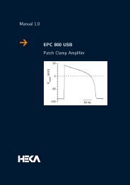
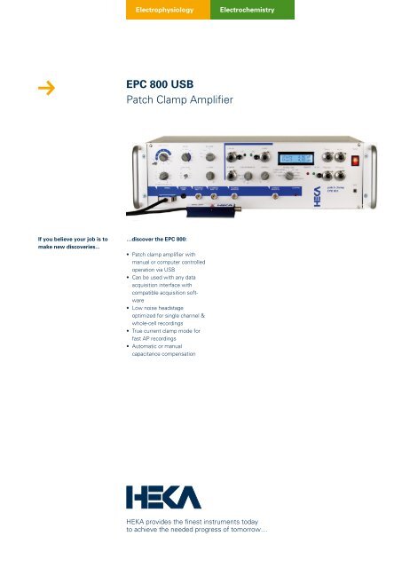
<strong>EPC</strong> <strong>800</strong> <strong>USB</strong><br />
Patch Clamp Amplifier<br />
…discover the <strong>EPC</strong> <strong>800</strong>:<br />
• Patch clamp amplifier with<br />
manual or computer controlled<br />
operation via <strong>USB</strong><br />
• Can be used with any data<br />
acquisition interface with<br />
compatible acquisition software<br />
• Low noise headstage<br />
optimized for single channel &<br />
whole-cell recordings<br />
• True current clamp mode for<br />
fast AP recordings<br />
• Automatic or manual<br />
capacitance compensation<br />
<strong>HEKA</strong> provides the finest instruments today<br />
to achieve the needed progress of tomorrow…<br />
1
2<br />
<strong>EPC</strong> <strong>800</strong><br />
Patch Clamp Amplifier<br />
For any researcher who desires manual user control through knobs<br />
and dials, while at the same time, longs for some degree of computer<br />
communication and automatic control, <strong>HEKA</strong> is excited to release the<br />
<strong>EPC</strong> <strong>800</strong> <strong>USB</strong>. This amplifier is truly a unique hybrid patch-clamp amplifier<br />
with its design and feature-set primarily based upon the manually<br />
controlled <strong>EPC</strong> 8. The <strong>EPC</strong> <strong>800</strong> <strong>USB</strong> is the most flexible patch<br />
clamp amplifier <strong>HEKA</strong> has ever produced in that it is a stand-alone<br />
amplifier that can be combined with any existing AD/DA interface and<br />
its compatible acquisition software.<br />
Improvements in comparison to the <strong>EPC</strong> 8:<br />
• Telegraphing outputs for Gain, Bandwidth, Mode & C-Slow<br />
• Automatic Vp-Offset, C-Fast & C-Slow compensation with the<br />
simple push of a button<br />
• Improved current monitor filters<br />
• <strong>USB</strong> 2.0 communication for software control of all amplifier<br />
functions<br />
• Low Frequency Voltage Clamp Mode (LFVC)<br />
• CC+Bridge Mode<br />
• Improved RS Comp Ranges
Features Operating Modes of the <strong>EPC</strong> <strong>800</strong> <strong>USB</strong><br />
The <strong>EPC</strong> <strong>800</strong> <strong>USB</strong> can be operated in three modes: Local, Local + Telegraphing and Remote. The<br />
decision of which mode to use not only depends on user preference of whether or not to have the<br />
functionality to turn knobs and switches, but also on what data acquisition software and interface the<br />
<strong>EPC</strong>-<strong>800</strong> <strong>USB</strong> is used with.<br />
1. Local:<br />
• Manual control by use of the knobs and switches on the front panel.<br />
• Vp-Offset, C-Fast and C-Slow compensation can be performed manually or automatically with the<br />
push of a button.<br />
• Amplifier can be used with ANY data acquisition interface and its compatible software.<br />
2. Local + Telegraphing:<br />
• Telegraphing outputs on the rear panel for Gain, Filter Bandwidth, Mode and C-Slow.<br />
Telegraphing features can be utilized by use with ANY AD/DA interface having telegraphing inputs.<br />
• Amplifier remains under manual control with use of the knobs and switches on the front panel.<br />
• Ability to perform automatic adjustments of Vp-Offset, C-Fast and C-Slow compensations are<br />
still possible.<br />
3. Remote:<br />
• Commands are sent and received through <strong>USB</strong> 2.0 communication.<br />
• The <strong>EPC</strong> <strong>800</strong> <strong>USB</strong> commands are open source and users are free to write their own interfacing<br />
to the device.<br />
• <strong>HEKA</strong> offers a dynamic link library (DLL) providing direct access to the amplifier and <strong>HEKA</strong><br />
data acquisition interfaces.<br />
• <strong>HEKA</strong>’s PATCHMASTER software supports all amplifier functionality in remote mode.<br />
• Amplifier can also be used with <strong>HEKA</strong>’s <strong>EPC</strong>MASTER software in combination with custom<br />
software or third-party software with the appropriate interface.<br />
• Front panel knobs and switches of the amplifier are inactive, with the exception of the<br />
LCD multi-position switch.<br />
3<br />
Electrophysiology
4<br />
<strong>EPC</strong> <strong>800</strong><br />
Patch Clamp Amplifier<br />
Acquisition Software Options<br />
1. Clampex software:<br />
The <strong>EPC</strong> <strong>800</strong> <strong>USB</strong> can be used with pCLAMP / Clampex software.<br />
Using pCLAMP requires the use of one of the series of Digidata<br />
interfaces. Use with older models such as the 1200 require the<br />
amplifier to be used in local mode. Use with more recent models<br />
such as the Digidata 1440A, that are equipped with telegraphing<br />
inputs, enable the <strong>EPC</strong> <strong>800</strong> <strong>USB</strong> to be used in a local + telegraphing<br />
mode. In this situation, the filter, gain and C-Slow values are telegraphed<br />
and displayed within Clampex.<br />
In local or local + telegraphing modes, the automatic C-Fast and<br />
C-Slow compensations features of the <strong>EPC</strong> <strong>800</strong> <strong>USB</strong> can be utilized.<br />
These are performed manually through the front panel and the<br />
results clearly illustrated in the Membrane Test panel of Clampex.<br />
2. PATCHMASTER software:<br />
<strong>HEKA</strong>’s PATCHMASTER software fully supports the <strong>EPC</strong> <strong>800</strong> <strong>USB</strong> in both local and remote modes of<br />
operation on either Windows (7, 2000, XP and VISTA) or Mac OS X operating systems. When using<br />
PATCHMASTER, the amplifier can be combined with any one of the <strong>HEKA</strong> / InstruTECH series of interfaces<br />
(ITC-16, ITC-18, ITC-1600, LIH-1600, LIH 8+8).<br />
When configured in Local mode, the amplifier operates manually with the front panel knobs and<br />
switches of the <strong>EPC</strong> <strong>800</strong> <strong>USB</strong> all active. As controls are changed, the same values that are displayed on<br />
the front panel LCD display are read and displayed in the PATCHMASTER amplifier window.
When in Remote mode, the<br />
controls and knobs of the<br />
<strong>EPC</strong> <strong>800</strong> <strong>USB</strong> are inactive. All<br />
amplifier settings, including<br />
automatic capacitance compensations,<br />
are fully controlled<br />
through the software. One of<br />
the many powerful features of<br />
PATCHMASTER is that it enables<br />
automatic control of the amplifier<br />
through user-defined protocols.<br />
Detailed information regarding<br />
PATCHMASTER functionality can<br />
be found in the PATCHMASTER<br />
brochure and user’s manual.<br />
3. <strong>EPC</strong>MASTER software<br />
<strong>HEKA</strong>’s <strong>EPC</strong>MASTER software consists of a virtual front panel of the <strong>EPC</strong> <strong>800</strong> <strong>USB</strong>. Although the<br />
program has no functions for data acquisition or analysis, it is very useful in that it provides users the<br />
option of setting amplifier parameters from a software panel instead of manually using the front panel<br />
controls.<br />
<strong>EPC</strong>MASTER is provided free of charge and should be used in conjunction with a custom data acquisition<br />
system i.e. IGOR Pro, Labview, pCLAMP, etc. The end result is a software controlled version of<br />
the amplifier that is extremely flexible with regard what particular data acquisition interface or software<br />
package it is being used with. This flexibility allows users to easily add an <strong>EPC</strong> <strong>800</strong> <strong>USB</strong> to their current<br />
setups without the need to purchase or learn a new data acquisition package.<br />
In this example, <strong>EPC</strong>MASTER<br />
is being used with a Digidata<br />
1440A and Clampex software,<br />
the <strong>EPC</strong> <strong>800</strong> <strong>USB</strong> is now considered<br />
to be operated in remote<br />
mode.<br />
4. Custom software<br />
The <strong>EPC</strong> <strong>800</strong> <strong>USB</strong> is flexible enough so that it can be integrated into customized experimental systems.<br />
The amplifier <strong>USB</strong> commands are open source and users are free to write their own interfacing to the<br />
device. <strong>HEKA</strong> provides a dynamic link library (DLL) which gives access to the amplifier and <strong>HEKA</strong> data<br />
acquisition interfaces. The DLL can be used with most programming languages, such as C, Pascal,<br />
Delphi and Visual Basic.<br />
5<br />
Electrophysiology
6<br />
<strong>EPC</strong> <strong>800</strong><br />
Patch Clamp Amplifier<br />
Acquisition Modes<br />
Three operating modes are provided: Voltage Clamp (VC), Current Clamp+Bridge (CC+Bridge) and Low<br />
Frequency Voltage Clamp (LFVC).<br />
Voltage Clamp (VC) mode recordings, ideal for recordings from whole-cell, cell-attached, single channel,<br />
loose patch or bilayer configurations.<br />
The current clamp mode of the <strong>EPC</strong> <strong>800</strong> <strong>USB</strong> is called CC + Bridge. Bridge compensation in current<br />
clamp mode acts in a similar way as RS compensation does in voltage clamp mode. It can be thought<br />
of as an enhanced current clamp mode that fully compensates the voltage drop via the series (access)<br />
resistance of the electrode (RS). In this mode, the stimulus artifact that is typically generated when<br />
injecting current is fully eliminated. The current clamp circuitry of the <strong>EPC</strong> <strong>800</strong> <strong>USB</strong> acts as a voltagefollower,<br />
thereby increasing the speed and stability of the circuit. Recording and following rapid events<br />
such as fast action potentials (AP) with patch or intracellular electrodes is possible.<br />
The “Low Frequency Voltage Clamp” (LFVC) mode is a modified current clamp mode that allows<br />
for the measurement of potential deflections such as action potentials or synaptic potentials, while<br />
the average potential is kept constant at a value chosen by the user with the LFVC HOLD potentiometer.<br />
The circuit thus works like a current clamp for fast signals and like a voltage clamp for low frequency<br />
signals. To achieve this, the measured membrane potential is low-pass filtered and compared to the<br />
LFVC HOLD potential. Current is injected into the cell to keep the membrane potential at the chosen LFVC<br />
potential. There are five time constants (1, 3, 10, 30 and 100) available for the LFVC mode that specifiy<br />
the speed of regulation. The feedback speed is highly dependent on the Gain Range settings.<br />
C-Fast and C-Slow Compensation<br />
Both C-Fast and C-Slow compensation routines can either be performed manually by turning the knobs<br />
or automatically by pressing the Auto buttons on the front panel. Both C-Fast and C-Slow compensation<br />
can be applied in all three headstage gain ranges. The C-Fast range is 0 to 15 pF in all gain ranges.<br />
C-Slow has 30, 100 and 1000 pF ranges.<br />
Multi-parameter Display<br />
An LCD panel can display the following parameter pairs: I / V Mon , C-Fast / τ-fast, C-Slow / R-Series, RS<br />
Range / Comp, VP / LFVC, I / V Hold , and Noise. The displayed parameters can either be individually<br />
selected via a multi-position switch or automatically set. If the Auto display mode is activated, the LCD<br />
panel will automatically display the value of the control as its modified by the user.<br />
Holding Potentials and VpOffset<br />
Ten-turn potentiometers are available on the front panel for VP OFFSET (± 200 mV), V HOLD (± 500 mV),<br />
I HOLD (± 50 nA or ± 500 pA) and LFVC HOLD (± 200 mV). VP Offset can be adjusted either manually or<br />
automatically by pressing the Auto button.
Technical Specifications<br />
General<br />
Included Accessories<br />
<strong>EPC</strong> <strong>800</strong> <strong>USB</strong> Headstage: 1<br />
<strong>EPC</strong> <strong>800</strong> <strong>USB</strong> Model Circuit: 1<br />
<strong>EPC</strong> <strong>800</strong> <strong>USB</strong> Manual: 1<br />
Pipette Holder: 1 (1.5 mm is standard, other diameters<br />
available upon request at<br />
no additional charge)<br />
<strong>USB</strong> Cable: 1 (3 meter <strong>USB</strong> 2.0 shielded cable)<br />
Power Cord: 1 (2 meter IEC type shielded)<br />
Dimensions Main Unit D x W x H: (31.1 x 48.3 x 14.5) cm /<br />
(12.3 x 19 x 5.7) inch<br />
Weight Main Unit 11.4 kg (24.8 lbs)<br />
Power Supply<br />
Power requirements are 125 W. The logic controlled power supply<br />
automatically switches the voltage range. Operational range is from<br />
90-130V or 210-250V at line frequencies of 50 or 60 Hz.<br />
A shielded transformer minimizes noise pickup from the power line<br />
frequencies.<br />
Ground Lines<br />
Signal ground (GND) is isolated from the chassis by a 10 Ω resistor to<br />
avoid ground loops. GND is accessible via a Banana plug on the front<br />
panel and also via a connector on the headstage.<br />
A Chassis ground (CHAS) is accessible via a Banana plug on the front<br />
panel and is connected to the ground line of the power cord.<br />
Headstage<br />
Dimensions: D x W x H: (90 x 16.9 x 14.3) mm<br />
(3.54 x 0.67 x 0.57) inch<br />
Resistors: Three feedback resistors. Gain ranges<br />
can be switched during the experiment.<br />
low gain range: 5 MOhm, ± 2 μA current range<br />
medium gain range: 500 MOhm, ± 20 nA current range<br />
high gain range: 50 GOhm, ± 200 pA current range<br />
Bandwidth (max): medium & low ranges: 100 kHz<br />
high range: 60 kHz<br />
Noise: (measured with an open input, 8-pole<br />
Bessel filter and 50 GΩ resistor)<br />
DC to 1 kHz < 0.03 pA RMS<br />
DC to 3 kHz < 0.08 pA RMS<br />
DC to 10 kHz < 0.225 pA RMS<br />
Filters<br />
The <strong>EPC</strong> <strong>800</strong> <strong>USB</strong> has a filter knob on the front panel with settings<br />
of 0.1, 0.3, 0.5, 0.7, 1, 3, 5, 7, 10, 30 and 100 kHz. It is an integrated<br />
filter comprised of two built-in filters for the current monitor signal.<br />
Filter 1 is a 5-pole, 10 to 100 kHz Bessel pre-filter. Filter 2 is a 4-pole,<br />
tunable 20 kHz Bessel filter. When the front panel knob is set to<br />
either 30 or 100 kHz, filter 2 is bypassed and the signal is straight<br />
filter 1. All of the other filter knob settings are filter 1 + filter 2.<br />
Output Gain<br />
low gain range: 0.005, 0.01, 0.02, 0.05, 0.1, 0.2 mV/pA<br />
medium gain range: 0.5, 1, 2, 5, 10, 20 mV/pA<br />
high gain range: 50, 100, 200, 500, 1000, 2000 mV/pA<br />
Pipette Offset<br />
± 200 mV (automatic or manual adjustment)<br />
Holding Commands<br />
Voltage Clamp: ± 500 mV with front panel knob<br />
± 1 V via external Stim Input<br />
Current Clamp + Bridge:<br />
Low CC Output Gain Range: I HOLD = ± 50 nA<br />
I MAX = ± 100 nA<br />
(available when switching from VC<br />
mode in low gain range)<br />
CC Stim Scaling = 10 pA<br />
High CC Output Gain Range: I HOLD = ± 500 pA<br />
I MAX = ± 1 nA<br />
(available when switching from VC<br />
mode in either medium or high gain<br />
ranges)<br />
CC Stim Scaling = 0.1 pA<br />
Low Frequency Voltage Clamp (LFVC):<br />
± 200 mV<br />
τ of 1, 3, 10, 30 or 100<br />
Capacitance Compensation<br />
C-Fast Compensation: 0 ⇔ 15 pF, 0 ⇔ 8 μs tau<br />
Automatic or manual compensation in all gain ranges<br />
C-Slow Compensation:<br />
Automatic or manual compensation in all gain ranges.<br />
OFF / 30, 100, 1000 pF switch<br />
30 pF range (1.0 ⇔ 30 pF)<br />
100 pF range (1.0 ⇔ 100 pF)<br />
1000 pF range (1.0 ⇔ 1000 pF)<br />
Injection Capacitors:<br />
The C-Fast compensation signal is injected via a 1 pF capacitor. The<br />
C-Slow compensation signals are injected via a 10 pF capacitor in<br />
medium and low gain and via a 1 pF capacitor in high gain range<br />
R-Series:<br />
0.1 MΩ ⇔ 200 MΩ (1000 pF range)<br />
1 MΩ ⇔ 200 MΩ (100 pF range)<br />
5 MΩ ⇔ 200 MΩ (30 pF range)<br />
Series Resistance Compensation<br />
Manual adjustment with range depending on cell capacitance.<br />
Equivalent Time Constants: 2 μs / 10 μs / 100 μs<br />
Range: 0 ⇔ 95%<br />
In current clamp mode: RS Comp serves as Bridge Compensation<br />
with a range of 0 ⇔ 120%<br />
Telegraphing Outputs<br />
(BNC connections on rear panel)<br />
Gain, Filter Bandwidth, Amplifier Mode, C-Slow<br />
7<br />
Electrophysiology
VKRPK1/1<br />
8<br />
Electrophysiology Electrochemistry<br />
<strong>HEKA</strong> <strong>Elektronik</strong><br />
<strong>Dr</strong>. <strong>Schulze</strong> <strong>GmbH</strong><br />
Wiesenstraße 71<br />
D-67466 Lambrecht/Pfalz<br />
Germany<br />
<strong>HEKA</strong> Electronics Incorporated<br />
47 Keddy Bridge Road<br />
R.R. #2<br />
Mahone Bay, NS B0J 2E0<br />
Canada<br />
<strong>HEKA</strong> Instruments Inc.<br />
2128 Bellmore Avenue<br />
Bellmore, New York 11710-5606<br />
USA<br />
General notice:<br />
Product names used herein<br />
are for identification purposes<br />
only and may be trademarks of<br />
their respective owners. <strong>HEKA</strong><br />
disclaims any and all rights in<br />
those marks.<br />
We reserve the right to effect<br />
technical changes as development<br />
progresses. Special versions<br />
are available on request.<br />
Further technical data are provided<br />
by a detailed description,<br />
which is available on request.<br />
A guarantee of one year applies<br />
on all instruments.<br />
Phone<br />
Fax<br />
Web Site<br />
Email<br />
Phone<br />
Fax<br />
Web Site<br />
Email<br />
Phone<br />
Fax<br />
Web Site<br />
Email<br />
+49 (0) 63 25 / 95 53-0<br />
+49 (0) 63 25 / 95 53-50<br />
http://www.heka.com<br />
sales@heka.com<br />
support@heka.com<br />
+1 902 624 0606<br />
+1 902 624 0310<br />
http://www.heka.com<br />
nasales@heka.com<br />
support@heka.com<br />
+1 516 882 1155<br />
+1 516 467 3125<br />
http://www.heka.com<br />
ussales@heka.com<br />
support@heka.com