PG 300 Manual - HEKA Elektronik Dr. Schulze GmbH
PG 300 Manual - HEKA Elektronik Dr. Schulze GmbH
PG 300 Manual - HEKA Elektronik Dr. Schulze GmbH

You also want an ePaper? Increase the reach of your titles
YUMPU automatically turns print PDFs into web optimized ePapers that Google loves.
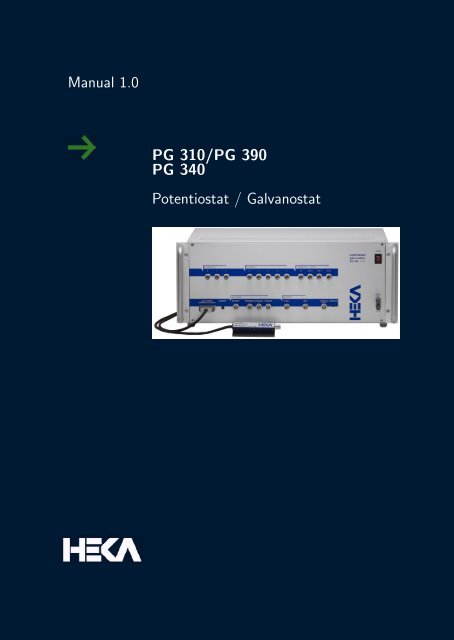
<strong>Manual</strong> 1.0<br />
<strong>PG</strong> 310/<strong>PG</strong> 390<br />
<strong>PG</strong> 340<br />
Potentiostat / Galvanostat
<strong>HEKA</strong> <strong>Elektronik</strong> Phone +49 (0) 6325 / 95 53-0<br />
<strong>Dr</strong>. <strong>Schulze</strong> <strong>GmbH</strong> Fax +49 (0) 6325 / 95 53-50<br />
Wiesenstrasse 71 Web Site http://www.heka.com<br />
D-67466 Lambrecht/Pfalz Email sales@heka.com<br />
Germany support@heka.com<br />
<strong>HEKA</strong> Electronics Inc. Phone +1 902 624 0606<br />
47 Keddy Bridge Road Fax +1 902 624 0310<br />
R.R. #2 Web Site http://www.heka.com<br />
Mahone Bay, NS B0J 2E0 Email nasales@heka.com<br />
Canada support@heka.com<br />
<strong>HEKA</strong> Instruments Inc. Phone +1 516 882-1155<br />
2128 Bellmore Avenue Fax +1 516 467-3125<br />
Bellmore, New York Web Site http://www.heka.com<br />
11710-5606 U.S.A. Email ussales@heka.com<br />
support@heka.com<br />
Title Page: Potentiostat/Galvanostat <strong>PG</strong> 310<br />
� 2004-2008 <strong>HEKA</strong> <strong>Elektronik</strong> <strong>Dr</strong>. <strong>Schulze</strong> <strong>GmbH</strong><br />
COMDP9/1
Contents<br />
1 Introduction 1<br />
1.1 Introducing the <strong>PG</strong> 310, <strong>PG</strong> 390, and <strong>PG</strong> 340 . . . . . . . . 1<br />
1.2 Naming Conventions . . . . . . . . . . . . . . . . . . . . . . 2<br />
1.3 Product Intended Usage . . . . . . . . . . . . . . . . . . . . 3<br />
1.4 Supplied Components . . . . . . . . . . . . . . . . . . . . . 3<br />
1.5 Unpacking . . . . . . . . . . . . . . . . . . . . . . . . . . . . 4<br />
1.6 Computer Requirements . . . . . . . . . . . . . . . . . . . . 4<br />
1.6.1 Windows . . . . . . . . . . . . . . . . . . . . . . . . 4<br />
1.6.2 Macintosh . . . . . . . . . . . . . . . . . . . . . . . . 4<br />
1.7 Support Hotline . . . . . . . . . . . . . . . . . . . . . . . . . 5<br />
2 Description of the Hardware 7<br />
2.1 Characteristics . . . . . . . . . . . . . . . . . . . . . . . . . 7<br />
2.1.1 Power Requirements . . . . . . . . . . . . . . . . . . 7<br />
2.1.2 Dimensions . . . . . . . . . . . . . . . . . . . . . . . 7<br />
2.1.3 True Plug-and-Play . . . . . . . . . . . . . . . . . . 7<br />
2.1.4 Hot-Swappable . . . . . . . . . . . . . . . . . . . . . 8<br />
2.1.5 Expandability . . . . . . . . . . . . . . . . . . . . . . 8<br />
2.1.6 DC Characteristics . . . . . . . . . . . . . . . . . . . 8<br />
2.1.7 Potentiostatic Mode . . . . . . . . . . . . . . . . . . 9<br />
2.1.8 Galvanostatic Mode . . . . . . . . . . . . . . . . . . 9
ii CONTENTS<br />
2.1.9 Dynamic Data . . . . . . . . . . . . . . . . . . . . . 9<br />
2.1.10 Initial Potential . . . . . . . . . . . . . . . . . . . . . 10<br />
2.1.11 Polarity Convention . . . . . . . . . . . . . . . . . . 10<br />
2.2 Main Unit . . . . . . . . . . . . . . . . . . . . . . . . . . . . 11<br />
2.2.1 Rear Panel . . . . . . . . . . . . . . . . . . . . . . . 11<br />
2.2.2 Front Panel . . . . . . . . . . . . . . . . . . . . . . . 11<br />
2.3 Simplified Block Diagram . . . . . . . . . . . . . . . . . . . 15<br />
3 Installation 17<br />
3.1 Connecting the <strong>PG</strong> <strong>300</strong> . . . . . . . . . . . . . . . . . . . . 17<br />
4 The Control Software 19<br />
4.1 Controlling the <strong>PG</strong> 310/390 - Main Functions . . . . . . . . 20<br />
4.1.1 Cell Connection . . . . . . . . . . . . . . . . . . . . 20<br />
4.1.2 Potential / Current settings . . . . . . . . . . . . . . 21<br />
4.1.3 Filter Settings . . . . . . . . . . . . . . . . . . . . . 23<br />
4.1.4 Additional Settings . . . . . . . . . . . . . . . . . . . 26<br />
4.1.5 Cell mode . . . . . . . . . . . . . . . . . . . . . . . . 27<br />
4.1.6 Auto Range . . . . . . . . . . . . . . . . . . . . . . . 27<br />
4.1.7 Macro Recording . . . . . . . . . . . . . . . . . . . . 28<br />
4.2 Hidden Controls . . . . . . . . . . . . . . . . . . . . . . . . 30<br />
4.2.1 Features for Macros . . . . . . . . . . . . . . . . . . 31<br />
4.3 Controlling the <strong>PG</strong> 340 - Special Functions . . . . . . . . . 32<br />
4.3.1 Electrode Conditions . . . . . . . . . . . . . . . . . . 33<br />
4.3.2 Cell Connection . . . . . . . . . . . . . . . . . . . . 33<br />
4.3.3 Potential/Current Settings . . . . . . . . . . . . . . 34<br />
4.3.4 Additional Settings . . . . . . . . . . . . . . . . . . . 34<br />
http://www.heka.com
CONTENTS iii<br />
4.3.5 Cell Mode . . . . . . . . . . . . . . . . . . . . . . . . 34<br />
5 Operating Modes 37<br />
5.1 Potentiostatic Mode . . . . . . . . . . . . . . . . . . . . . . 38<br />
5.1.1 Differential Amplifier . . . . . . . . . . . . . . . . . . 38<br />
5.1.2 Current Amplifier . . . . . . . . . . . . . . . . . . . 39<br />
5.1.3 Control Amplifier . . . . . . . . . . . . . . . . . . . . 39<br />
5.2 Galvanostatic Mode . . . . . . . . . . . . . . . . . . . . . . 42<br />
5.2.1 IR Compensation . . . . . . . . . . . . . . . . . . . . 43<br />
6 Appendix I: Technical Data 45<br />
6.1 <strong>PG</strong> <strong>300</strong> Series . . . . . . . . . . . . . . . . . . . . . . . . . 45<br />
6.1.1 Digital I/O Connector . . . . . . . . . . . . . . . . . 45<br />
6.1.2 Digital In Connector . . . . . . . . . . . . . . . . . . 46<br />
6.1.3 Digital Out Connector . . . . . . . . . . . . . . . . . 47<br />
6.2 <strong>PG</strong> <strong>300</strong> USB Series . . . . . . . . . . . . . . . . . . . . . . 48<br />
6.2.1 Digital I/O Connector . . . . . . . . . . . . . . . . . 48<br />
6.2.2 Digital In Connector . . . . . . . . . . . . . . . . . . 49<br />
6.2.3 Digital Out Connector . . . . . . . . . . . . . . . . . 49<br />
http://www.heka.com
1. Introduction<br />
1.1 Introducing the <strong>PG</strong> 310, <strong>PG</strong> 390, and<br />
<strong>PG</strong> 340<br />
The <strong>PG</strong> <strong>300</strong> series potentiostat/galvanostat feature state-of-the-art amplifier<br />
technology. They include amplification ranges for large currents, new<br />
hardware filters and an external preamplifier design (optional) to reduce<br />
noise levels for small currents. The most significant advance is the complete<br />
software controlled adjustment of the amplifier. This provides the tools<br />
necessary to perform virtually every electrochemical experiment. This also<br />
allows for the simplification and automation of experimental procedures<br />
and gives enormous flexibility for future extensions. The instant automatic<br />
versatile and easy-to-use macro features yield measurements of the highest<br />
quality, all while retaining the possibility of full manual control of the<br />
amplifier. Therefore, this instrument fulfills the needs of testing industrial<br />
electrodes and scientific research. The versatility of the amplifier and its<br />
superb technical specifications make the <strong>PG</strong> <strong>300</strong> the instrument of choice<br />
for all electrochemical experiments.<br />
The integration of the <strong>PG</strong> <strong>300</strong> amplifier with the LIH 8+8 AD/DA interface<br />
and the connected computer constitutes a further step in the minimization<br />
of total recording noise. Complemented by the intrinsic low noise level of<br />
the <strong>PG</strong> <strong>300</strong> itself with the low current preamplifier, this integrated system<br />
effectively eliminates all interferences because it is fully decoupled by optical<br />
isolation that in conventional systems often arise from ground loops.<br />
Furthermore, the full digital control by a computer running our dedicated<br />
software achieves a well-compensated measuring arrangement necessary for<br />
a minimum of noise.<br />
Automatic calibration and testing procedures implemented in the software<br />
control of the <strong>PG</strong> <strong>300</strong> guarantees exact functioning of the amplifier at all<br />
times. The user can easily run a calibration process whenever it might be
2 Introduction<br />
Figure 1.1: <strong>PG</strong> 340 USB Potentiostat / Galvanostat<br />
necessary. The highly advanced integration of hardware and software of<br />
the <strong>PG</strong> <strong>300</strong> system eliminates compatibility problems, time consuming setup<br />
operations, and training time. Furthermore, it saves the expenses for<br />
additional instruments. The <strong>PG</strong> <strong>300</strong> controlled by the software Potmaster<br />
and combined with a computer is equivalent to a fully equipped set-up<br />
which includes a potentiostat/galvanostat, digital storage oscilloscope, variable<br />
analog filter, sophisticated pulse generator, and a full featured data<br />
acquisition and analysis system.<br />
1.2 Naming Conventions<br />
<strong>PG</strong> 310 USB, <strong>PG</strong> 390 USB, and <strong>PG</strong> 340 USB<br />
Throughout the present manual we will address all three amplifier types as<br />
“<strong>PG</strong> <strong>300</strong>”. We will explicitly mention the particular amplifiers, where it is<br />
required.<br />
http://www.heka.com
1.3 Product Intended Usage 3<br />
1.3 Product Intended Usage<br />
The <strong>HEKA</strong> <strong>PG</strong> <strong>300</strong> is intended for research use only in a laboratory by<br />
persons trained in its use. Users are expected to be able to properly operate<br />
the <strong>PG</strong> <strong>300</strong> and associated instruments.<br />
The <strong>HEKA</strong> <strong>PG</strong> <strong>300</strong> is not intended for medical use. The <strong>HEKA</strong> <strong>PG</strong> <strong>300</strong> is<br />
not intended for use in life support situations, or in situations were improper<br />
operation or failure of the <strong>PG</strong> <strong>300</strong> can result in personal injury.<br />
<strong>HEKA</strong> makes no representation that the design, implementation, testing,<br />
or manufacture of the <strong>PG</strong> <strong>300</strong> meet reasonable standards for use as a medical<br />
product. As stated in the <strong>HEKA</strong> Limited Warranty Statement, supplied<br />
with each product, ”<strong>HEKA</strong> expressly disclaims all warranties to buyer except<br />
the limited warranty set forth above, including without limitation to<br />
any and all implied warranties of merchantability and fitness for a particular<br />
purpose.”<br />
1.4 Supplied Components<br />
The following items should have been packed with your <strong>PG</strong> <strong>300</strong>:<br />
� 1 <strong>PG</strong> <strong>300</strong> potentiostat/galvanostst<br />
� 1 USB 2.0 shielded cable (3 meters)<br />
� 1 <strong>HEKA</strong> CD-ROM<br />
� 1 Printed user’s manual<br />
� 1 power cord (110 or 220 Volt depending on application)<br />
If any of these items are missing please contact <strong>HEKA</strong> or your dealer immediately.<br />
http://www.heka.com
4 Introduction<br />
1.5 Unpacking<br />
After unpacking the <strong>PG</strong> <strong>300</strong> and accessories from the shipping carton,<br />
please inspect each piece for any signs of shipping damage. Please contact<br />
the delivering carrier and <strong>HEKA</strong> immediately if there is any damage.<br />
Do not dispose of the shipping carton. The carrier will want to examine the<br />
shipping carton to process a damage claim. <strong>HEKA</strong> insures all shipments<br />
to cover shipping damage. It is also advisable to keep the shipping carton<br />
in the event that the instrument must be returned for service.<br />
1.6 Computer Requirements<br />
1.6.1 Windows<br />
� Pentium 4 or faster processor<br />
� Windows 2000, XP or Vista<br />
� Available USB 2.0 Hi-Speed port (480 Mbits/second)<br />
� CD-ROM or internet access<br />
1.6.2 Macintosh<br />
� Macintosh G5 or faster processor<br />
� Mac OS X (10.4 or higher)<br />
� Available USB 2.0 Hi-Speed port (480 Mbits/second)<br />
� CD-ROM or internet access<br />
Please note that many newer computer systems are supplied with multiple<br />
USB 2.0 ports, but only some of these ports are capable of Hi-Speed<br />
operation. The <strong>PG</strong> <strong>300</strong> will work on the slower speed ports, but the maximum<br />
transfer rates will be greatly reduced. For optimal performance, the<br />
<strong>PG</strong> <strong>300</strong> should only be connected to a USB 2.0 Hi-Speed port.<br />
http://www.heka.com
1.7 Support Hotline 5<br />
If your computer system does not have a Hi-Speed USB 2.0 port, then<br />
a USB 2.0 adapter may be used. These adapters are available in many<br />
configurations (PCI, PC Slot, etc).<br />
1.7 Support Hotline<br />
If you have any question, suggestion, or improvement, please contact<br />
<strong>HEKA</strong>’s support team. The best way is to send us an e-mail or fax specifying:<br />
� Your postal and E-mail address (or fax number)<br />
� The program name: Potmaster<br />
� The program version number: v2.30, v2.32<br />
� Your operating system and its version: MacOS 10.4, Windows XP<br />
Prof., etc.<br />
� Your type of computer: Mac G5, Pentium 4, 1.8 GHz, etc.<br />
� Your acquisition hardware, if applicable: <strong>PG</strong> 310 USB, LIH 8+8<br />
� The series number and version of your potentiostat.<br />
� The questions, problems, or suggestions you have<br />
� Under which conditions and how often the problem occurs<br />
We will address the problem as soon as possible.<br />
<strong>HEKA</strong> <strong>Elektronik</strong> <strong>GmbH</strong><br />
Wiesenstrasse 71<br />
D-67466 Lambrecht/Pfalz<br />
Germany<br />
phone: +49 (0) 6325 9553 0<br />
fax: +49 (0) 6325 9553 50<br />
e-mail: support@heka.com<br />
web: http://www.heka.com<br />
http://www.heka.com
6 Introduction<br />
http://www.heka.com
2. Description of the Hardware<br />
2.1 Characteristics<br />
2.1.1 Power Requirements<br />
AC-power 110 V or 220 V, 50 to 60 Hz,<br />
170 W maximum (<strong>PG</strong> 310)<br />
260 W maximum (<strong>PG</strong> 390)<br />
2.1.2 Dimensions<br />
Housing 43 cm W x 18 cm H x 35 cm D<br />
(16.9” W x 7.1” H x 13.8” D)<br />
Front panel 48,3 cm x 18 cm<br />
(19” x 7.1”) with two handles<br />
The <strong>PG</strong> <strong>300</strong>model potentiostat/galvanostat can be mounted in a standard<br />
19” rack assembly.<br />
Weight 12.2 kg (27 lb)<br />
2.1.3 True Plug-and-Play<br />
Simply connect the <strong>PG</strong> <strong>300</strong> to an available Hi-Speed USB 2.0 port on the<br />
host computer system using the supplied USB cable. The computer will<br />
automatically identify the LIH 8+8 and install the appropriate driver software,<br />
if needed, to operate it. This connection scheme greatly reduces<br />
start-up time. It is no longer necessary to open the computer to add a<br />
board. Simply make all of the connections to the recording setup and execute<br />
the data acquisition software. Within minutes, data can be acquired.
8 Description of the Hardware<br />
2.1.4 Hot-Swappable<br />
Another advantage of the USB based <strong>PG</strong> <strong>300</strong> data acquisition interface is<br />
that it can be installed or removed while the computer is running. Just plug<br />
the device in, use it, and unplug it when done. There is no need to power<br />
down the computer. The <strong>PG</strong> <strong>300</strong> is self-enumerating and self-identifying.<br />
The device driver is dynamically loaded when connected and dynamically<br />
unloaded when unplugged.<br />
2.1.5 Expandability<br />
If an application requires more channels than are available on a single<br />
<strong>PG</strong> <strong>300</strong>, then multiple units can be connected and fully synchronized. Each<br />
<strong>PG</strong> <strong>300</strong> unit requires a dedicated Hi-Speed USB 2.0 port and an external<br />
cable connection between the units. This external connection is used to<br />
synchronize the acquisition clocks of the units and is made with a standard<br />
CAT5 patch cable. A single external trigger will start the multiple units<br />
simultaneously. Please note that <strong>PG</strong> <strong>300</strong> interfaces installed on separate<br />
computers can also be synchronized in the same manner. The number<br />
of units that can be installed is only limited by the number of available<br />
Hi-Speed USB 2.0 ports.<br />
2.1.6 DC Characteristics<br />
<strong>PG</strong> 310 <strong>PG</strong> 390<br />
Counter Electrode:<br />
Compliance Voltage ±20 V Compliance Voltage ±20 V<br />
Output current ±2 A Output current ±1 A<br />
Continuous Power:<br />
20 W 90 W<br />
Resolution current monitor: 0.02 % of full range<br />
Resolution voltage monitor: 1 mV<br />
Input specifications (reference electrode):<br />
impedance: 100 GΩ in parallel with 1.5 pF<br />
http://www.heka.com
2.1 Characteristics 9<br />
2.1.7 Potentiostatic Mode<br />
<strong>PG</strong> 310 <strong>PG</strong> 390<br />
Counter electrode:<br />
Potential range: ±20 V ±90 V<br />
2.1.8 Galvanostatic Mode<br />
Current range ±1µA to ±2A (<strong>PG</strong> 590: ±1 A) in 8 (7) steps<br />
Minimum resolution 0.02 %<br />
2.1.9 Dynamic Data<br />
Small signal rise time 0.1 µs up to 200 µs maximum in 4 steps<br />
controlled by a 3-pole Bessel filter<br />
Slew rate 10 V/µs<br />
Bandwidth > 1 MHz in 1 mA-range at -3dB<br />
Phase shift < 10� at 200 kHz<br />
2.1.9.1 Low Current Preamplifier<br />
The input circuitry is contained in a hybrid integrated circuit (available<br />
only for <strong>PG</strong> 310).<br />
Current measuring resistors:<br />
500 MΩ (1 nA; 100 pA)<br />
5 MΩ (100 nA; 10 nA)<br />
Noise measured with open input:<br />
8-pole Bessel filter; 1 nA - 100 pA, 500 MΩ? feedback resistor:<br />
DC to 10 kHz: ¡ 400 fA (RMS)<br />
Maximum bandwidth: 100 kHz<br />
2.1.9.2 Filters<br />
The <strong>PG</strong> 310/<strong>PG</strong> 390 contains three built-in filters.<br />
http://www.heka.com
10 Description of the Hardware<br />
Voltage filter The voltage monitor can be filtered by a 3-pole Bessel filter<br />
in three steps of 10, 100, or 1000 Hz.<br />
Current filter The current monitor can be filtered by a 4-pole filter with<br />
selectable Bessel or Butterworth characteristics from 0.5 to 16 kHz (Bessel)<br />
or to 25 kHz (Butterworth).<br />
Bandwidth control The power amplifier bandwidth can be controlled in 8<br />
steps from 0.1 to <strong>300</strong> kHz.<br />
2.1.10 Initial Potential<br />
Total range of ±10 V can be set manually or through software control.<br />
2.1.11 Polarity Convention<br />
The <strong>PG</strong> <strong>300</strong> model potentiostats/galvanostats conforms to the polarity convention<br />
that defines a cathodic current to be negative. That is a current<br />
is negative if reduction is taking place. Positive current is anodic that is<br />
a current is defined as positive if oxidation is taking place. The current<br />
monitor and the monitor display are consistent with this convention.<br />
In potentiostatic operation, applying a more positive potential will results<br />
in a more anodic current. In contrast, a more negative potential applied<br />
will results in a more cathodic current. This is also true for EXTERNAL<br />
INPUT Stimulus voltages.<br />
In the galvanostatic mode, applying a more positive current will tend to<br />
cause a more anodic current. Conversely, a more negative applied current<br />
will cause a more cathodic current. This sensing applies for any current<br />
change regardless of its source. This includes the <strong>PG</strong> <strong>300</strong> EXTERNAL INPUT.<br />
Note: The EXTERNAL INPUT has 5 KΩ input impedance in<br />
both the potentiostatic and galvanostatic modes.<br />
http://www.heka.com
2.2 Main Unit 11<br />
2.2 Main Unit<br />
The <strong>PG</strong> <strong>300</strong> main unit contains the analog main board with the analog scan<br />
generator, the display board including two digital display modules and the<br />
power-supply.<br />
2.2.1 Rear Panel<br />
Voltage Switch: A switch on the rear panel of the main unit selects<br />
between the 110 and 220 volt operation. Make sure that the switch is in<br />
the proper position, and that the correct fuse is installed.<br />
Rear-panel connectors: Three 40-pin connectors and an analog trigger<br />
input and output allow connection of the <strong>PG</strong> <strong>300</strong> to other devices:<br />
USB: This is the connection to the host computer, that allows the computer<br />
to communicate with the <strong>PG</strong> <strong>300</strong>.<br />
Digital I/O: TTL-level, digital input and output lines are available here<br />
for the control and monitoring of digital signals.<br />
Trigger In: Input for an external trigger to start data acquisition when<br />
the LIH 8+8 is waiting for an external trigger. This mode is set in POT-<br />
MASTER when either Trigger Series or Trigger Sweeps is selected in the<br />
Pulse Generator.<br />
� Gate Out: Output for trigger signals. In common application this<br />
output is not used.<br />
2.2.2 Front Panel<br />
Power Switch: In order to be initialized properly, the <strong>PG</strong> <strong>300</strong> should be<br />
switched on before starting the POTMASTER program. However, this<br />
program allows you to re-initialize the amplifier in case you forgot to turn<br />
it on first.<br />
Note: Since the calibration settings of the potentiostat have<br />
been determined for a warmed-up potentiostat, switch on the<br />
http://www.heka.com
12 Description of the Hardware<br />
potentiostat ∼15 min before starting an experiment. This will<br />
ensure that the potentiostat has warmed up to the regular working<br />
temperature and that the calibration parameters are most<br />
accurate.<br />
GND-CHAS: The chassis (CHAS) is connected to the ground line of the<br />
power cord, as is typical of most instruments. The Signal ground (GND) is<br />
kept separate from the chassis to avoid ground loops, but can be connected<br />
to it through an external connector. To run the potentiostat with floating<br />
ground, remove the external connector. Both with floating and with<br />
chassis ground, the signal ground can be connected to other parts of the<br />
experimental setup if necessary. In the first case, the banana jack of Signal<br />
ground provides a high-quality connection to the other parts. In the latter<br />
case the banana jack in the external connector must be used.<br />
DA and AD connectors: The BNC connectors to the built-in laboratory<br />
interface (LIH 8+8) are grouped into Digital to Analog (DA) converter<br />
outputs and Analog to Digital (AD) converter inputs.<br />
DA Outputs: Four DA channels are provided (0-3). They carry the<br />
following signals:<br />
DA-0 Free (Trigger output)<br />
DA-1 Free (Trigger output)<br />
DA-2 TEST (Trigger output)<br />
DA-3 SCAN = Internal stimulus output (used to monitor the stimulus)<br />
Note: These are output connectors. Make sure that you never<br />
feed stimuli into these outputs!<br />
DA-0 to DA-2 are typically used to trigger an oscilloscope or an isolation<br />
unit. Up to three triggers can be assigned by POTMASTER (see POT-<br />
MASTER <strong>Manual</strong> Chapter 10 - Pulse Generator). Using the same DA<br />
channel for more than one trigger can create simple pulse patterns. The<br />
convention for these patterns is that the DA template for the first trigger is<br />
loaded first. The non-zero values for the following triggers are then added,<br />
i.e. in case of overlapping the DA values will become additive. DA-2 is also<br />
http://www.heka.com
2.2 Main Unit 13<br />
intended to be used for tests which have not yet been implemented. DA-3<br />
is internally wired as the internal stimulus generator.<br />
AD Inputs: The LIH 8+8 interface provides eight AD channels (0-7). AD<br />
channels 5 and 6 are internally connected to the <strong>PG</strong> <strong>300</strong>potentiostat circuit<br />
and are used by the software supplied. Channel 5 is labeled ”U-Cell”<br />
and carries the U-Cell Monitor output. Channel 6 is labeled ”I-Cell” and<br />
carries the I-Cell Monitor output. Channel 7 carries the output of the<br />
<strong>PG</strong> <strong>300</strong>’s internal multiplexer. You normally should not connect anything<br />
to channels 5 and 6, unless you wish to inspect the signals for diagnostic<br />
reasons. However, channels 0-4 are freely available for application programs.<br />
For example, the POTMASTER program can use these channels<br />
to monitor temperature, pH-value, or outputs from other sensors.<br />
Standby: The user can disconnect the electrochemical cell from the potentiostat<br />
by pressing a hardware standby button. The Standby mode of<br />
the potentiostat is indicated by flashing of the button. The cell cannot be<br />
connected to the potentiostat by remote control, if the hardware standby<br />
button is pressed. Hence, be sure that the hardware standby button does<br />
not flash while an experiment is being performed. This button can be used<br />
to disconnect the cell independently of the POTMASTER software.<br />
Electrodes: As usual for common potentiostats/galvanostats, the current<br />
flow through the electrochemical cell is measured or controlled between the<br />
counter and working electrodes. In the potentiostatic mode the <strong>PG</strong> <strong>300</strong>can<br />
be driven in both the three- and four-electrode mode. In any case, the<br />
voltage is controlled between the both reference electrodes, Reference I<br />
and Reference II. In the three-electrode mode, however, the Reference II<br />
connection is short-circuited to the working electrode. Hence, in this mode<br />
the usual setup is realized for controlling the voltage between reference and<br />
working electrodes.<br />
Counter Electrode: Connect your counter or auxiliary electrode here.<br />
Reference I: In the three electrode mode, connect your reference electrode<br />
here. In the four-electrode mode, connect your first reference electrode here.<br />
Reference II: In the four-electrode mode, connect your second reference<br />
electrode here. In the three-electrode mode, Reference II is not used.<br />
Working Electrode: Connect your working electrode here.<br />
http://www.heka.com
14 Description of the Hardware<br />
Important note: The electrode connectors are supplied with<br />
a voltage up to 90 V. Take care not to touch these connectors<br />
to avoid an electric shock hazard.<br />
U-Cell Monitor: This output signal provides a monitor for the electrochemical<br />
cell voltage, i.e. the potential difference between the working<br />
and reference electrodes (three-electrode mode) or both reference electrodes<br />
(four-electrode mode). The output impedance is 50 Ω. This signal may be<br />
viewed on the software oscilloscope.<br />
I-Cell Monitor: This output signal provides a monitor for the current<br />
density flowing through the electrochemical cell. A voltage between the<br />
limits of 10 V is supplied by this output, where 10 V means a current<br />
density of 100 % of the selected current range. The output signals are<br />
filtered in accordance with the settings in the software. Positive voltages<br />
correspond to positive current flows. Typically, the I-Cell output is fed to<br />
an oscilloscope for monitoring the progress of the experiment. This signal<br />
may also be viewed on the software oscilloscope.<br />
External Input: Signals from an external stimulus source are applied<br />
here; they can be summed with the internal stimulus if desired. The combined<br />
stimulus signal is passed through a 2-pole filter to round off stepwise<br />
changes in voltage. This avoids non-linearities (from slew-limiting amplifiers)<br />
in the command processing circuitry. and also reduces the amplitude<br />
of the current transients from rapid charging of the electrode. Four degrees<br />
of filtering, specified as the rise times (time from 10% to 90% of the amplitude<br />
of a step change) are available in the software: 2 µs, which is the<br />
minimum required to avoid non-linearities in the internal circuitry, and 20<br />
µs, which is preferable for all but the fastest measurements, to reduce the<br />
capacitive transients. For slow experiments 200 µs and 2000 µs filters can<br />
also be used.<br />
OVERLOAD: This LED lights whenever an amplifier saturates in the<br />
current monitor pathway. This indicator is important in order to avoid destroying<br />
the electrochemical cell. It is particularly useful as it will indicate<br />
clipping by internal amplifiers even if the output voltage is not saturated,<br />
because of filtering. Moreover, this LED lights whenever digital information<br />
is sent from the computer to the <strong>PG</strong> <strong>300</strong>potentiostat.<br />
http://www.heka.com
2.3 Simplified Block Diagram 15<br />
2.3 Simplified Block Diagram<br />
Although the <strong>PG</strong> <strong>300</strong>potentiostat/galvanostat is a complex instrument,<br />
the organization of its analog part is straightforward and depicted in the<br />
following figure. The succeeding paragraphs discuss the <strong>PG</strong> <strong>300</strong>potentiostat/galvanostat,<br />
in combination with the different operating modes, in<br />
some detail.<br />
http://www.heka.com
16 Description of the Hardware<br />
http://www.heka.com
3. Installation<br />
3.1 Connecting the <strong>PG</strong> <strong>300</strong><br />
1. The <strong>PG</strong> <strong>300</strong> can be installed into a standard nineteen-inch instrument<br />
rack or used as a desktop unit. If installing on a rack, please<br />
do not use the <strong>PG</strong> <strong>300</strong> as a shelf to support any other instrument.<br />
The <strong>PG</strong> <strong>300</strong> case was not designed to do this and damage to the<br />
front panel will result. To minimize noise, it is advisable to mount<br />
the LIH 8+8 away from devices that emit high-frequency signals (i.e<br />
monitors, power supplies, etc).<br />
2. Connect the power cord to the <strong>PG</strong> <strong>300</strong>. The internal power supply<br />
used in the <strong>PG</strong> <strong>300</strong> is an auto switching multi-voltage supply that will<br />
operate from 90 Volts to 250 Volts. Make sure that the <strong>PG</strong> <strong>300</strong> power<br />
cord is plugged into a properly grounded AC receptacle. Improper<br />
grounding of the <strong>PG</strong> <strong>300</strong> could result in an electrical shock hazard.<br />
It is advisable to plug all equipment into a common outlet strip. This<br />
will minimize power line induced noise in the system.<br />
3. Install the USB cable from the USB connector on the rear panel of<br />
the <strong>PG</strong> <strong>300</strong>, labeled USB, to an available USB 2.0 Hi-Speed port<br />
on the computer. This connection should be made directly to the<br />
computers USB 2.0 port and not to a USB HUB.<br />
4. As soon as the <strong>PG</strong> <strong>300</strong> is detected by the host operating system the<br />
appropriate system files will be initialized and the <strong>PG</strong> <strong>300</strong> will be<br />
ready for use.<br />
Important note: The host operating system treats the<br />
<strong>PG</strong> <strong>300</strong> as it would any Flash memory device. Therefore,<br />
only standard operating system files are required. This<br />
provides ease of installation and flexibility for moving the<br />
<strong>PG</strong> <strong>300</strong> from one computer system to another.
18 Installation<br />
5. If multiple <strong>PG</strong> <strong>300</strong> interfaces are to be connected, repeat the steps<br />
as outlined above for each unit. In addition, for the acquisition clocks<br />
to be properly synchronized, a connection between the Master clock<br />
output of one unit to the Slave clock input of the other (connectors<br />
located on the rear panel) must be made using standard CAT5 patch<br />
cables.<br />
Important note: Please note that the sync clock is a highfrequency<br />
signal. The shortest possible length patch cable<br />
should be used.<br />
6. Before powering up, please recheck all connections. If all connections<br />
are proper then the power LED will illuminate once the <strong>PG</strong> <strong>300</strong> is<br />
powered ON.<br />
Important note: Please note that the Status LED will not<br />
be illuminated until the acquisition software has initialized<br />
the interface.<br />
The <strong>PG</strong> <strong>300</strong> is now connected and ready to go.<br />
http://www.heka.com
4. The Control Software<br />
The Potentiostat window is used for controlling, adjusting and displaying<br />
the amplifier settings. The window might differ depending on the type
20 The Control Software<br />
of amplifier you are controlling with Potmaster. We will describe the<br />
window of the <strong>PG</strong> <strong>300</strong> in most detail and focus to special details only<br />
when describing the windows of other amplifiers.<br />
4.1 Controlling the <strong>PG</strong> 310/390 - Main Functions<br />
The <strong>PG</strong> <strong>300</strong>Potentiostat window is used for controlling, adjusting and<br />
displaying the Pg 310/390 Potentiostat/Galvanostat operating<br />
modes.<br />
The Potentiostat window has<br />
three different Panes (Monitor,<br />
Tuning, and Show All) to allow<br />
switching between the display of<br />
different sets of controls.<br />
Monitor: Shows only the most<br />
important parameters and functions<br />
of the window like Cell<br />
Potential, Cell Current,<br />
Current Density and Charges.<br />
Tuning: Shows additionally<br />
the settings of Filters,<br />
IR-compensation and Current<br />
Auto Range.<br />
Show All: Shows all controls.<br />
4.1.1 Cell Connection<br />
Cell/Standby/OCP: Via<br />
these buttons the connection of<br />
the Pg 310/390 Potentiostat/Galvanostat<br />
to the cell<br />
can be controlled.<br />
http://www.heka.com
4.1 Controlling the <strong>PG</strong> 310/390 - Main Functions 21<br />
Cell: Connects all the electrodes to the respective inputs of the Pg<br />
310/390 Potentiostat/Galvanostat. In the potentiostatic mode the<br />
cell potential is controlled by the Pg 310/390 Potentiostat, and the<br />
current flowing through the cell is displayed as I-Cell. In the galvanostatic<br />
mode the current flow through the cell is controlled by the Pg 310/390<br />
Galvanostat, and the respective cell potential is shown in the E-Cell<br />
display.<br />
In the Standby mode all the connections are switched off, and the potential<br />
can neither be read nor set.<br />
In the OCP mode the counter-electrode is disconnected. The cell is in the<br />
zero current state, and the open cell potential is exhibited in the E-Cell<br />
display. The small Set insert button is used to set the Initial Potential<br />
value to the actual Open Cell Potential.<br />
Note: It is also possible to switch to the Standby mode by<br />
pressing the ‘0’ key of the numeric keypad.<br />
4.1.2 Potential / Current settings<br />
E-cell: Cell potential monitor.<br />
The cell potential is displayed in<br />
relation to the chosen Zero Potential<br />
(E-zero) .<br />
I-cell: Direct current monitor. The current flowing through the cell is<br />
displayed.<br />
Charge: The charge which is passing through the cell is subdivided into<br />
anodic charge and cathodic charge. With respect to electrochemical notation,<br />
the anodic charge is due to the positive portion of the current flow<br />
through the cell, and the cathodic charge, which is displayed as absolute<br />
value, is due to the negative current flow.<br />
Initial Potential: Sets the desired initial value of the cell potential in the<br />
potentiostatic mode. The range is ±10 V and can be set by dragging the<br />
mouse or entering via the keyboard.<br />
� <strong>Dr</strong>agging with the mouse will change the potential in 1 mV steps.<br />
http://www.heka.com
22 The Control Software<br />
� Pressing ← and → changes E-initial in steps of 10 mV.<br />
� Pressing �Option� ← / → (MacOS) or Ctrl ← / → (Windows) will<br />
change Einitial in 1 mV steps.<br />
In the galvanostatic mode, the item will display the Iinitial(Initial current).<br />
The current is calculated by multiplying the current density and the electrode<br />
area, which can be specified either in the Configuration or Parameter<br />
window. It is also possible to set I-initial (Density) instead of I-initial. In<br />
the potentiostatic mode, the I-initial (Density) field is not activated.<br />
Current Range: Sets the scaling of the current monitor output (I-cell).<br />
The ranges are 1µA to 10A incremented by decades.<br />
To set the current range, click with the mouse on the Current Range button<br />
and selecting the desired range in the pop-up window by tagging.<br />
If the high gain pre-amplifier is connected to the Pg 310 Potentiostat/Galvanostat,<br />
the current ranges from 100pA to 100nA are selectable.<br />
The Auto Range mode is also available (see below).<br />
If the High Current Booster Hcb 20 is connected, the 20 A range is<br />
selectable.<br />
The current range is calculated by multiplying the current density range<br />
and the electrode area, which can be specified either in the Configuration<br />
window or the Parameter window . Alternatively, the user can choose the<br />
range of current density instead of the current range. The unit of the<br />
current density is labeled with a prime, e.g., A.<br />
If there is a saturation of amplifiers in the current monitor circuitry, a<br />
blinking box labelled Over on the Current Range button is displayed. This<br />
is a warning that excess artifacts or noise may occur as a result of the<br />
saturation of amplifiers.<br />
Break + Standby: Corresponds to the buttons Break and Standby, thus<br />
stopping all data acquisition immediately and turning the cell to Standby<br />
mode.<br />
Auto Zero: In Standby mode a connected external preamplifier is set to<br />
zero current. Please use this option in case of eliminating current offsets of<br />
your external preamplifier.<br />
http://www.heka.com
4.1 Controlling the <strong>PG</strong> 310/390 - Main Functions 23<br />
Charge Reset: Resets both the anodic and the cathodic charge.<br />
Amplifier Mode: Allows a<br />
selection between potentiostatic<br />
and galvanostatic mode.<br />
4.1.3 Filter Settings<br />
Notch Filter: The<br />
<strong>PG</strong> 310/390 Potentiostat/Galvanostat<br />
provides a<br />
notch filter for both the voltage<br />
and the current pathway. The<br />
notch frequency (50 Hz or 60<br />
Hz) is pre-set at the factory as<br />
desired by the customer, and<br />
cannot be set by the user. If the<br />
notch filter is On, incoming signals at the power supply frequency will be<br />
effectively filtered out.<br />
Control Amplifier Bandwidth, Stimulus Filter, Voltage Filter,<br />
Current Filter: This filters can be set either manually or automatically.<br />
(The Notch Filter has to be switched manually by the user in any case.<br />
For automatic filter mode, please activate the Auto Filter option in the<br />
Configuration window. The automatic settings dependance is that way:<br />
� The automatic settings of the Control Amplifier Bandwidth, the Voltage<br />
Filter, and the Current Filter depend on the user defined Sample<br />
Interval and Filter Factor in the Pulse Generator (Free waveform)<br />
window.<br />
� The automatic setting of the Stimulus Filter depends on the Sample<br />
Interval.<br />
If the Auto Filter mode is selected, the filter settings are unable for manual<br />
settings and displayed with grayish numbers.<br />
http://www.heka.com
24 The Control Software<br />
Note: If you are using an electrochemical cell with a high capacity<br />
and low Ohmic drop, a problem may arise with the automatic<br />
setting of the Stimulus Filter. In combination with a<br />
high frequency Stimulus Filter a pulse-like stimulus may cause<br />
oscillations at the potential steps with the use of such cells. In<br />
this case, try to select the manual filter mode and reduce the<br />
frequency of the Stimulus Filter. The other three filter settings<br />
proposed in the Auto Filter mode can be left unchanged.<br />
Control Amplifier Bandwidth: The potential control amplifier can be<br />
filtered to avoid oscillations of the control circuit. Eight of the nine possible<br />
settings of the bandwidth (plus Max) are available:<br />
• 10 Hz • 100 Hz • <strong>300</strong> Hz • 1 kHz • 3 kHz • 10 kHz • 30 kHz • 100 kHz<br />
• Max<br />
The possible settings depend on the Pg 310/390 Potentiostat version:<br />
� If you are using a Pg 310/390 Potentiostat/Galvanostat with<br />
a ”A” or ”B” labeled serial number, the low frequency bandwidth of<br />
10 Hz will not be available.<br />
� If you are using a Pg 310/390 Potentiostat/Galvanostat with<br />
a ”C” or ”D” labeled serial number, the high frequency bandwidth<br />
of <strong>300</strong> kHz will not be available.<br />
Note: A transient problem may arise if the potential change is<br />
very fast in combination with a low bandwidth setting. There<br />
will be a rise time lag in the cell potential with respect to the<br />
given potential pulse. The time constant as the inverse of the<br />
bandwidth defines the shortest time domain over which the cell<br />
will accept a significant perturbation.<br />
Stimulus Filter: The stimulus can be filtered (2-pole Bessel) to reduce<br />
the amplitude of fast capacitance transients when the speed of potential<br />
changes is not critical. Four settings are available:<br />
• 500 kHz • 50 kHz • 5 kHz • 0.5 kHz<br />
http://www.heka.com
4.1 Controlling the <strong>PG</strong> 310/390 - Main Functions 25<br />
Note: In a ramp segment the stimulus change is step-like<br />
rather than line-like. The number of steps needed for representing<br />
the ramp is defined by the quotient of the segment length<br />
and the ”sample interval” (see also Chapter Pulse Generator,<br />
page ??). To improve the smoothness of the stimulus change,<br />
these steps are filtered to yield exponential, which reach about 63<br />
percent of the step height during a term of one time constant.<br />
Hence, a filtered stimulus will become a chain of exponential,<br />
which exhibits a phase shift relative to the unfiltered stimulus.<br />
For instance, if you choose a filter time constant equal to the<br />
sample interval, the filtered stimulus will be a nearly smooth line<br />
with a phase shift of about 90 percent of the step length (i.e. of<br />
the sample interval).<br />
Voltage Filter: The voltage output (U-cell monitor) can be filtered by a<br />
3-pole Bessel filter to reduce high frequency noise. The bandwidth can be<br />
set in four steps:<br />
• 10 Hz • 100 Hz • 1000 Hz • Max<br />
With the selection of Max no filtering is active and all frequencies are<br />
allowed to pass the AD channel.<br />
Current Filter: Controls a switchable analog Bessel/Butterworth filter<br />
(4-pole) in the current monitor pathway. The menu provides the following<br />
settings:<br />
� Bessel<br />
� Butterworth<br />
� Bypass (e.g., no filter active)<br />
<strong>Dr</strong>agging the mouse or entry on the keyboard allows bandwidth fine adjustment<br />
from 0.1-16 kHz in 0.1 kHz steps (Bessel) or 0.1-25.5 kHz (Butterworth).<br />
They differ in the following way:<br />
� The Bessel setting is the best characteristic for general use. As such<br />
it is always used in automatic mode.<br />
http://www.heka.com
26 The Control Software<br />
� The Butterworth response rolls off more rapidly with frequency and<br />
is useful mainly for power spectral analysis.<br />
Under most conditions a 10 kHz bandwidth is more than ample, and the<br />
filtering reduces the high-frequency noise substantially.<br />
Note: In automatic mode always the Bessel filter is used.<br />
4.1.4 Additional Settings<br />
IR-Comp.: The series resistance<br />
compensation corrects for<br />
the voltage drop between the<br />
reference and working electrodes<br />
under conditions of high access<br />
resistance or high current flow between counter- and working electrode.<br />
In the 4-Electrode Mode the serial resistance between both reference electrodes<br />
is corrected. The compensation is based on the value of R-series,<br />
which can be changed by dragging the mouse or entering on the keyboard<br />
(range: 0 to 1 M) and will be effective only when IR-Comp is On (see also<br />
<strong>PG</strong>310/390 <strong>Manual</strong> – IR Compensation).<br />
Ext. Input: The External Input (front panel of the Pg 310/390) is<br />
scaled by a selectable factor (range: 0.1x and 1x), to allow for different<br />
external stimulators. It is strongly recommended to set Ext. Input to Off<br />
(i.e., equal to zero), if no external stimulator is connected to Ext. Input.<br />
This will prevent pick-up of external noise.<br />
Note: The E-Initial (the Initial Potential) is not affected by<br />
changing the external scale factor. The scaling will only affect<br />
the initial potential, if the user sets the Initial Potential<br />
externally (e.g., with a stimulator or another computer).<br />
Reset: Selecting this button will reset the Pg 310/390 to its initial default<br />
configuration. Reset is very useful for defining the initial state of the<br />
Pg 310/390, when recording a macro. It will reset the DA channels to<br />
zero. E-Initial (the Initial Potential) will be unchanged by resetting the<br />
Pg 310/390.<br />
http://www.heka.com
4.1 Controlling the <strong>PG</strong> 310/390 - Main Functions 27<br />
4.1.5 Cell mode<br />
Cell Mode: Two separate cell<br />
setups are supported by the Pg<br />
310/390 Potentiostat:<br />
� 3 Electrode Mode<br />
� 4 Electrode Mode<br />
The 3 Electrode Mode consists of a working, a counter and a reference<br />
electrode. In this mode the second reference electrode input (Reference<br />
II) on the front panel of the Pg 310/390 is short-circuited to the working<br />
electrode, so that the potentiostat controls the voltage between the working<br />
and reference electrodes. This commonly used mode is the default setting.<br />
The 4 Electrode Mode provides two distinct reference electrodes (Reference<br />
I and Reference II on the front panel of Pg 310/390), between which<br />
the potentiostat controls the voltage.<br />
4.1.6 Auto Range<br />
During a sweep Potmaster<br />
can adjust the current range to<br />
higher or lower ranges if the current<br />
was out of bounds. This function is available during slow data acquisition<br />
when in the Pulse Generator window Auto Current Range is<br />
selected.<br />
Min: Specifies the lower threshold of current within the given current<br />
range in percentages of full range. If the current reaches the Min percentage<br />
of the actual current range, the next lower current range is selected and<br />
the current resolution increases. The minimum value for Min is 1%, the<br />
maximum value for Max is 100%.<br />
Max: Specifies the upper threshold of current within the given current<br />
range in percentages of full range. If the current reaches the Max percentage<br />
of the actual current range, the amplifier switches to the next higher current<br />
http://www.heka.com
28 The Control Software<br />
range. The current resolution decreases. The values for Max range between<br />
1% and 100%.<br />
Note: Auto Range is also possible with the extended current<br />
ranges of the External Preamplifier and the High Current<br />
Booster.<br />
The desired thresholds of current within a given current range are defined in<br />
the Min / Max boxes in percentages of full range. For instance, a Max setting<br />
with 90% will force Potmaster to switch to the next higher current range<br />
if the current exceeds 90% of the actual range.<br />
4.1.7 Macro Recording<br />
The following buttons give you some of the features from the <strong>PG</strong>F-Editor<br />
menue Macros option (see Chapter Macros).<br />
� Record corresponds to Start Recording.<br />
� The macro buttons corresponds to Execute [1..7].<br />
� Clicking on an empty macro after recording and choosing Assign and<br />
name recorded macro corresponds to Stop Recording. Here the index<br />
of the macro is directly the index number of the empty macro button.<br />
� Clicking on Record at the end of recording aborts recording directly.<br />
You can save 20 macros at<br />
once, whereas the macro items<br />
of macro 8..20 and higher are in<br />
that part of the window which<br />
gets exposed when you zoom out<br />
the <strong>PG</strong> <strong>300</strong> window (see below in Chapter Hidden Controls, page 30).<br />
You have the option of actually executing all actions as they are entered,<br />
or of disabling execution and only logging the actions to the macro. This<br />
option you have to set in the <strong>PG</strong>F-Editor menu Macro options before you<br />
record.<br />
http://www.heka.com
4.1 Controlling the <strong>PG</strong> 310/390 - Main Functions 29<br />
Record: To start macro recording, click on the Record button. Then,<br />
perform all desired actions. (The Notebook window will print a protocol<br />
of the macro actions.) You may record up to 50 actions in the <strong>PG</strong> <strong>300</strong>,<br />
Oscilloscope and Online Analysis windows. To specify a parameter<br />
value, enter it as usual by dragging or keyboard entry. When clicking on a<br />
macro button you will see a dialog with the following options:<br />
� Delete Macro: This will erase the selected macro.<br />
� Cancel: This will disregard the macro call. You can continue recording.<br />
� Record call to macro itself: This will execute the macro as part<br />
of the macro being recorded (embedded macro call).<br />
� Copy contents of macro: This will copy each of the macro instructions<br />
of the selected macro into the macro being recorded. This avoids<br />
the problems of recursive macros (i.e., macros calling each other and<br />
causing an infinite loop).<br />
� Assign and name recorded macro: This will prompt you to give<br />
a name to the macro. This name will become the button text. This<br />
is the function you need for saving a newly recorded macro!<br />
To abort recording a macro, click again on Record and the sequence just<br />
recorded will be lost.<br />
Normally, macros are only available until you leave the program. You have<br />
to save the macros explicitly in a file on disk (see <strong>PG</strong>F-Editor menu Macro<br />
options options), if you want to use it further.<br />
Macro 1..39: To start a recorded macro you can either click on the desired<br />
macro button or hit the key with the same number on the numeric block<br />
of your keyboard (macros 1..9).<br />
In a macro file (*.mac) up to 40 macros (1.. 39) can be stored. One macro<br />
can exist of max. 255 instruction lines.<br />
http://www.heka.com
30 The Control Software<br />
4.2 Hidden Controls<br />
Some rarely used controls are on the right and bottom of the Potentiostat<br />
window. They can be accessed by clicking on the zoom box of the window<br />
or by pulling the window with the mouse on the right and lower sight.<br />
The following features can be found at the bottom of the Potentiostat<br />
window.<br />
Ampl. Mode switch: set<br />
E/I-init: This feature ensures<br />
that by switching the Amplifier<br />
Mode between potentiostatic<br />
and galvanostatic, no current or voltage leap will occur. Thus, in the potentiostatic<br />
mode the actual current is measured and applied to the cell<br />
after the amplifier mode is switched to galvanostatic. This is the default<br />
setting.<br />
If the function Ampl. Mode switch: keep E/I-init is chosen, current<br />
or voltage leaps may occur and affect the electrochemical processes at the<br />
working electrode.<br />
http://www.heka.com
4.2 Hidden Controls 31<br />
4.2.1 Features for Macros<br />
These features can be found at the right side of the Potentiostat window.<br />
Relative Value: This control button allows<br />
the performance of relative changes<br />
of control settings during macro recording.<br />
Note: For instance, if you<br />
want to compare different<br />
data monitors because of different<br />
filter settings, you can<br />
start a sweep while recording<br />
a macro, change the current<br />
filter setting relative to<br />
the first one by 1 kHz (click<br />
on Relative Value and then<br />
set filter to 1 kHz), start the<br />
sweep again, etc., and save<br />
the macro.<br />
Beep: Plays the system sound. In<br />
recording a macro it is useful to acoustically<br />
indicate the end of an experiment<br />
or other events.<br />
Macros 8..39: Buttons for all macros<br />
with index numbers higher than 7.<br />
Wait: This button is used to pause a macro execution. Pausing is indicated<br />
by a flashing Initial Potential field, which displays ”Continue?” and the<br />
Wait button, as well as by a ”Beep” sound. Macro execution is resumed by<br />
a click on the mouse. The Wait button can be used to inspect a particular<br />
sweep when playing a collection of sweeps. The time in seconds for the<br />
Wait function is set in the field above.<br />
Delay: This determines how many seconds the program has to wait<br />
before the next action is started by the Pg 310/390 Potentio-<br />
http://www.heka.com
32 The Control Software<br />
stat/Galvanostat. When the Record button is activated, the label<br />
changes to Wait.<br />
4.3 Controlling the <strong>PG</strong> 340 - Special Functions<br />
With the Potmaster software you can also control the Pg 340 Bipotentiostat/Galvanostat.<br />
The main feature of the Pg 340 Ring/Disc Potentiostat/Galvanostat<br />
is its design as a double potentiostat which<br />
allows to control two independent working-electrodes. This not only<br />
provides the tools to control rotating ring-disc electrodes, which are<br />
almost essential for the thorough study of mechanisms and kinetics of<br />
electrochemical reactions. It also allows the control of microelectrodes<br />
and ultra-microelectrodes connecting two external preamplifiers and<br />
makes innovative microelectrochemical technologies possible as generatorand<br />
collector-electrode mode for a Scanning Electrochemical Microscope<br />
(SECM).<br />
The Pg 340 allows to set a sample substrate to a well defined potential<br />
versus a reference electrode while recording currents in the lower pA-range<br />
at an ultramicroelectrode in the same solution. Using two current channels<br />
strongly different currents can be simultaneously recorded. The bipotentiostat<br />
Pg 340 is therefore the heart of the <strong>HEKA</strong> ElProScan, the<br />
new developed Electrochemical Probe Scanner which is much more then a<br />
SECM.<br />
The Potentiostat window of Pg 340 is amended with some buttons<br />
and functions for the two working electrodes, in comparison to the<br />
normal Potentiostat window, (see Chapter 4.1 <strong>PG</strong> 310/390 Potentiostat/Galvanostat).<br />
http://www.heka.com
4.3 Controlling the <strong>PG</strong> 340 - Special Functions 33<br />
4.3.1 Electrode Conditions<br />
Via the buttons Disk and Ring the active electrode can be set and controlled.<br />
� Disk – all settings in the Potentiostat window apply to the DISK<br />
electrode<br />
� Ring – all settings in the Potentiostat window apply to the RING<br />
electrode<br />
4.3.2 Cell Connection<br />
Cell/Standby/OCP: Via these buttons the connection of the<br />
Pg310/390 Potentiostat/Galvanostat to the cell can be controlled.<br />
Cell: Connects all the electrodes to the respective inputs of the Pg 340<br />
Bipotentiostat/Galvanostat. In the potentiostatic mode the cell potential<br />
is controlled by the Pg 340, and the current flowing through the cell<br />
is displayed as I-Cell. In the galvanostatic mode the current flow through<br />
the cell is controlled by the Pg 340, and the respective cell potential is<br />
shown in the ECell display.<br />
Note: The galvanostatic mode can only be set with the DISK<br />
electrode.<br />
In the Standby mode all the connections are switched off, and the potential<br />
can neither be read nor set.<br />
In the OCP mode the counter-electrode is disconnected. The cell is in the<br />
zero current state, and the open cell potential of the selected electroded –<br />
either DISK or RING - is exhibited in the E-Cell display. The small Set<br />
insert button is used to set the Initial Potential value to the actual Open<br />
Cell Potential.<br />
Note: It is also possible to switch to the Standby mode by<br />
pressing the ‘0’ key of the numeric keypad.<br />
http://www.heka.com
34 The Control Software<br />
4.3.3 Potential/Current Settings<br />
Almost all functions are the same as for the standard Pg 310/390<br />
Postentiostat/Galvanostat, see Chapter 4.1 <strong>PG</strong> 310/390 Potentiostat/Galvanostat.<br />
However, there are some small differences to be taken<br />
into account.<br />
All settings apply to the selected electrode, e.g., DISK or RING.<br />
Exceptions are:<br />
� Standby, Cell and OCP, which act on the DISC and the RING electrode.<br />
� Control Amplifier Bandwidth Filtering, which acts on the DISC<br />
and the RING electrode.<br />
� Stimulus Filter, which is active only with the DISK electrode.<br />
4.3.4 Additional Settings<br />
The IR-compensation in the 3-Electrode Mode as well as in the 4-Electrode<br />
Mode applies only to the DISC electrode.<br />
4.3.5 Cell Mode<br />
Cell Mode: Two separate cell setups are supported by the Pg 340 Potentiostat:<br />
� 3 Electrode Mode<br />
� 4 Electrode Mode<br />
The 3 Electrode Mode consists of a working (DISK and RING), a counter<br />
and a reference electrode. In this mode the second reference electrode input<br />
(Reference II) on the front panel of the Pg 340 is short-circuited to the<br />
working electrode (DISK), so that the potentiostat controls the voltage<br />
http://www.heka.com
4.3 Controlling the <strong>PG</strong> 340 - Special Functions 35<br />
between the working (DISK and RING) and reference electrodes. This<br />
commonly used mode is the default setting.<br />
The 4 Electrode Mode provides two distinct reference electrodes (Reference<br />
I and Reference II on the front panel of Pg 340), between which the<br />
potentiostat controls the voltage.<br />
http://www.heka.com
36 The Control Software<br />
http://www.heka.com
5. Operating Modes<br />
The <strong>PG</strong> 500 is fundamentally an instrument for controlling cell potential<br />
or current and measuring electric currents and potentials. In low current<br />
ranges it uses a current-to-voltage (I-U) converter circuit to convert the<br />
currents to an analog voltage, which is then made available at the current<br />
monitor output for display or recording. In higher current ranges, a resistor<br />
cascade replaces the I-U converter. In the potentiostatic mode, cell currents<br />
are recorded at the same time while the potential is controlled. In the<br />
galvanostatic mode, the current flowing through the cell is specified, and<br />
the potential at the working electrode is recorded. The connection of the<br />
electrochemical cell to the <strong>PG</strong> 500 potentiostat/ galvanostat is possible<br />
in three different cell modes and can be controlled manually or by the<br />
Potpulse software.<br />
� In the Standby mode, the cell is not connected to the REFERENCE and<br />
COUNTER electrodes; however the working electrode is always connected<br />
to the cell.<br />
� In the OCP (open cell potential) mode, the REFERENCE and<br />
WORKING electrodes are connected to a measuring circuit with high<br />
input impedance (see section Differential Amplifier below) for allowing<br />
observation of the equilibrium potential (zero current potential).<br />
� In the Cell mode, each of the three electrodes is connected to the<br />
terminals of the potentiostat/galvanostat circuit.<br />
Note: for any cell mode selection, the working electrode is connected<br />
to the current amplifier.
38 Operating Modes<br />
5.1 Potentiostatic Mode<br />
This is the basic amplifier mode and is implemented by the circuitry shown<br />
schematically in the figure below.<br />
5.1.1 Differential Amplifier<br />
The cell potential (reference vs. working electrodes) is derived from<br />
a generated scan (pulse) with a variable offset added from the Initial<br />
Potential control. An external voltage (External Input) can be superimposed<br />
on this software-generated signal. The sum of these two sources<br />
is displayed and monitored as the VOLTAGE Monitor signal. Furthermore,<br />
the high-resistance reference electrode input (input impedance of 100 GΩ)<br />
is very sensitive to any capacitive load or change in those electrode leads.<br />
Please bear in mind that even movement of the electrode leads may cause<br />
changes in capacitance. To maximize the bandwidth of the electrode inputs<br />
and to minimize the potential errors due to lead capacitance, a shield<br />
that remains fixed at the potential of the signal lead guards the reference<br />
electrode connector. This is realized by an electrometer amplifier that feeds<br />
the signal potential to the lead shield, that is, the outer part of the BNC<br />
http://www.heka.com
5.1 Potentiostatic Mode 39<br />
connectors (see sketch above). Thus, it is not permissible to ground (set<br />
to earth potential) the shield of the coaxial cable used for the reference<br />
electrode lead.<br />
5.1.2 Current Amplifier<br />
In a low current range situation, that is, 1 µA to 1 mA, the current flowing<br />
through the cell is converted to a voltage by the I-U converter (see sketch<br />
above). If the current range is changed, the appropriate feedback resistor<br />
will selected for that range. In higher current ranges, a resistor cascade<br />
replaces the I-U converter, and the potential drop across this resistor corresponds<br />
to the cell current. In both cases, the current amplifier amplifies<br />
the resulting voltage. Bear in mind that the <strong>PG</strong> 500 series potentiostat<br />
does not incorporate a truly grounded-potential working electrode. However<br />
at low currents the working electrode is virtually grounded by the I-U<br />
converter input and at higher currents the voltage difference between the<br />
working electrode and ground can be as high as the potential drop across<br />
the current-sensing resistor.<br />
5.1.3 Control Amplifier<br />
The control amplifier circuit is basically a ±20 V, ±2 A (<strong>PG</strong> 510) or ±90 V,<br />
±1 A (<strong>PG</strong> 590) power operational amplifier. The various input signals supported<br />
are summed together at the input of the control amplifier (Internal<br />
Scan Generator, External Input and IR-Comp. Please note that the External<br />
Input is scalable by 1 or 0.1 only in REMOTE mode in local mode it<br />
defaults to 1. A sum of these voltages in excess of ±10 V is not permitted.<br />
The control amplifier unit is actually more complex than is shown in the<br />
upper schematic diagram and consist of the power amplifier itself, a buffer<br />
to boost the power amplifier output, and the bandwidth control.<br />
The output of the buffer is driven to the voltage that is required to cause<br />
the feedback signal to be equal in its absolute value and opposite in sign<br />
to the summed input voltage. The bandwidth of the control amplifier is<br />
selected within the limits of 30 Hz to 100 kHz by changing a capacitor in<br />
the feedback loop. The maximal bandwidth (MAX) with non-capacitive<br />
feedback is defined by the internal circuit of the operational amplifiers and<br />
http://www.heka.com
40 Operating Modes<br />
exceeds 1 MHz in the 1 mA range at -3 dB representing a signal amplitude<br />
reduction of a factor of approximately 0.7. The control amplifier is faster<br />
without any bandwidth settings however the circuit may oscillate under IR<br />
Compensation.<br />
Whenever currents are passing through the electrochemical cell, there is<br />
always a potential control error IRu, due to the uncompensated resistance<br />
Ru. Usually, this error is small, or can be reduce to an insignificant level<br />
by selecting a proper choice of cell parameters. As long as this error is<br />
proportional to the cell current, using a signal of equal magnitude and<br />
opposite polarity can compensate it. The magnitude of the compensation<br />
signal is determined by the setting of the Ru compensation control on<br />
the current amplifier (positive feedback compensation). In the <strong>PG</strong> 500<br />
series potentiostat, a voltage compensation based on this positive feedback<br />
compensation scheme is implemented. When IR Compensation is enabled,<br />
a fraction of the voltage (opposite in sign) developed by the I-U converter<br />
or resistance cascade in the current measuring circuit is fed back through<br />
a digital-to-analog converter (DAC) as an additional input to the control<br />
amplifier. This internal signal is applied to the working electrode terminal.<br />
The following equivalent circuit illustrates the principle of compensation<br />
illustrated in a comprehensive manner.<br />
In this model the desired potential difference between the working and reference<br />
electrodes is maintained at 0.100 V. As a result of IR compensation,<br />
however, this potential difference no longer includes a voltage drop error due<br />
http://www.heka.com
5.1 Potentiostatic Mode 41<br />
to uncompensated resistance. That is, the reference electrode is virtually<br />
shifted. Thus, the Voltage Monitor output signal, 0.100 V in this example,<br />
is the signal coming from the differential amplifier, that is, 0.110 V,<br />
corrected for the amount of IR compensation; thus, 200 µA·50 Ω = 0.010 V .<br />
Please note that the uncompensated resistance can be defined only as a fraction<br />
of the resistance across which the current is determined as a voltage.<br />
As a consequence, the highest compensation resistance as well as the resolution<br />
of the compensation resistance depends on the current range, too,<br />
therefore the IR compensation procedure must be performed for each current<br />
range used. The highest compensation resistance (Rcomp max.) and<br />
the resolution of the compensation resistance are a function of the current<br />
range.<br />
http://www.heka.com
42 Operating Modes<br />
5.2 Galvanostatic Mode<br />
In the galvanostatic mode, the cell current is controlled by involving only<br />
two cell elements, the counter and working electrodes, in the control circuit<br />
(see figure below). The potential of the working electrode with respect to<br />
the reference electrode is followed and monitored by the differential amplifier,<br />
which acts as an summing measuring circuit. However the amplifier<br />
makes no contribution to the control circuit.<br />
For performing galvanostatic measurements, the connections between the<br />
cell and the potentiostat/galvanostat system are the same as those for<br />
potentiostatic operation.<br />
The functions of the three amplifiers (control, current, and differential amplifiers)<br />
are the same as described in the section for the potentiostatic mode.<br />
The more detailed description above, including shielding of the reference<br />
electrodes, the different I-U converter provided for high and low current<br />
ranges, the bandwidth control of the control amplifier and the summing<br />
of the various input signals, also applies to galvanostatic operation. The<br />
input signals, consisting of an Initial Current, a generated Scan and an<br />
http://www.heka.com
5.2 Galvanostatic Mode 43<br />
External Input, are provided as a voltage, whereby a voltage magnitude of<br />
10 V means a cell current of 100 percent of the selected current range.<br />
Note: in the galvanostatic mode the output of the differential<br />
amplifier also includes a contribution from uncompensated<br />
resistance. Compensation of this potential error is performed<br />
by IR compensation with positive feedback as described in the<br />
section above.<br />
5.2.1 IR Compensation<br />
Whenever currents are passing through the electrochemical cell, there is<br />
always a potential control error IRu because of the uncompensated resistance<br />
Ru. If a cathodic current flows, the true working electrode potential<br />
will be less negative than the nominal value. The opposite holds for an<br />
anodic current. Usually, this error is small, or can be made insignificant by<br />
a proper choice of the cell parameters. As long as this error is proportional<br />
to the cell current, it can be compensated by using a signal of equal magnitude<br />
but of opposite polarity. The magnitude of the compensation signal<br />
is determined by the setting of the Ru compensation control on the current<br />
amplifier (positive feedback compensation). In the <strong>PG</strong> <strong>300</strong> series potentiostat/galvanostat,<br />
a voltage compensation based on this positive feedback<br />
compensation scheme is implemented. When IR Compensation is enabled<br />
in the POTPULSE program, a fraction of the voltage (opposite in sign)<br />
developed by the I-U converter or resistance cascade in the current measuring<br />
circuit is fed back through a digital-to-analog converter (DAC) as<br />
an additional input to the control amplifier. This internal signal is effective<br />
at the working electrode terminal.<br />
The working electrode potential (vs. reference electrode) differs from the<br />
desired value defined by the sum of the software and external settings by<br />
the control error I(Ru-Rcompensation).<br />
In galvanostatic operation the differential amplifier is not part of the control<br />
circuit, and the voltage drop error due to uncompensated resistance should<br />
only be corrected, if the cell potential is monitored. IR compensation will<br />
act as an additional voltage to the U-Cell Monitor; it is determined by the<br />
Rcompensation setting and the output signal from the current amplifier.<br />
http://www.heka.com
44 Operating Modes<br />
The following equivalent circuit illustrates the principle of compensation in<br />
an easily comprehensible manner.<br />
In this model circuit the desired potential difference between the working<br />
and reference electrodes is maintained at 0.100 V. As a result of IR compensation,<br />
however, this potential difference no longer includes a voltage drop<br />
error due to uncompensated resistance. That is, the reference electrode<br />
is virtually shifted. Thus, the U-Cell monitor output signal, 0.100 V in<br />
this example, is the signal coming from the differential amplifier (Reference<br />
Electrode I vs. Reference Electrode II ), that is, 0.110 V, corrected for the<br />
amount of IR compensation; thus, 200 µA ∗50 Ω = 0.010 V.<br />
Please note that the uncompensated resistance can be defined only as a<br />
fraction of the resistance across which the current is determined as a voltage.<br />
As a consequence, the highest compensation resistance as well as the<br />
resolution of the compensation resistance depends on the current range,<br />
too, and thus the IR compensation procedure has to be performed for each<br />
current range used. The highest compensation resistance (Rcomp max.)<br />
and the resolution of the compensation resistance are a function of the<br />
current range, as follows.<br />
http://www.heka.com
6. Appendix I: Technical Data<br />
6.1 <strong>PG</strong> <strong>300</strong> Series<br />
6.1.1 Digital I/O Connector<br />
The digital IN and OUT lines of this connector carry TTL-compatible<br />
signals. The connector is intended to connect other <strong>HEKA</strong> devices, such<br />
as the TIB 14 to the <strong>PG</strong> <strong>300</strong>. For other purposes the Digital In connector<br />
and the Digital Out connector should be used.<br />
PIN 1 of the 40-pin connector is labelled with a small arrow:<br />
Figure 6.1: Digital I/O connector of the <strong>PG</strong> <strong>300</strong>
46 Appendix I: Technical Data<br />
Figure 6.2: Digital I/O connector of the <strong>PG</strong> <strong>300</strong><br />
6.1.2 Digital In Connector<br />
The Digital In connector at the rear panel can be used to read TTL trigger<br />
signals from external devices.<br />
http://www.heka.com<br />
Figure 6.3: Digital In connector of the <strong>PG</strong> <strong>300</strong>
6.1 <strong>PG</strong> <strong>300</strong> Series 47<br />
6.1.3 Digital Out Connector<br />
The Digital Out connector at the rear panel of the <strong>PG</strong> <strong>300</strong> amplifiers can<br />
be used to trigger external devices, which require TTL inputs. The signals<br />
of pin 21 (OUT-0) to 23 (OUT-2) can also be accessed from the BNC<br />
trigger outputs at the front panel of the amplifier.<br />
Figure 6.4: Digital Out connector of the <strong>PG</strong> <strong>300</strong><br />
http://www.heka.com
48 Appendix I: Technical Data<br />
6.2 <strong>PG</strong> <strong>300</strong> USB Series<br />
6.2.1 Digital I/O Connector<br />
The digital IN and OUT lines of this connector carry TTL-compatible<br />
signals. The connector is intended to connect other <strong>HEKA</strong> devices, such<br />
as the TIB 14 to the <strong>PG</strong> <strong>300</strong>amplifier. For other purposes the Digital In<br />
connector and the Digital Out connector should be used.<br />
PIN 1 of the 40-pin connector is labelled with a small arrow:<br />
Figure 6.5: Digital I/O connector of the <strong>PG</strong> <strong>300</strong>USB<br />
Figure 6.6: Digital I/O connector of the <strong>PG</strong> <strong>300</strong>USB<br />
http://www.heka.com
6.2 <strong>PG</strong> <strong>300</strong> USB Series 49<br />
6.2.2 Digital In Connector<br />
The Digital In connector at the rear panel can be used to read TTL trigger<br />
signals from external devices.<br />
Figure 6.7: Digital In connector of the <strong>PG</strong> <strong>300</strong>USB<br />
6.2.3 Digital Out Connector<br />
The Digital Out connector at the rear panel of the <strong>PG</strong> <strong>300</strong> amplifiers can<br />
be used to trigger external devices, which require TTL inputs. The signals<br />
of pin 21 (OUT-0) to 23 (OUT-2) can also be accessed from the BNC<br />
trigger outputs at the front panel of the amplifier.<br />
http://www.heka.com
50 Appendix I: Technical Data<br />
Figure 6.8: Digital Out connector of the <strong>PG</strong> <strong>300</strong>USB<br />
http://www.heka.com
Index<br />
Ampl.Mode Switch, 30<br />
Amplifier<br />
Bandwidth, 24<br />
Amplifier Mode, 23<br />
Auto Filter, 23<br />
Auto Range, 27<br />
Bandwidth, 24<br />
Beep<br />
Macro Execution, 31<br />
Bipotentiostat, 32<br />
Break + Standby<br />
Macro Execution, 22<br />
Cell Mode, 27, 34<br />
Charge<br />
Monitor, 21<br />
compensation resistance<br />
highest, 44<br />
resolution, 44<br />
computer interface, 11<br />
Control Amplifier, 39<br />
Current<br />
Monitor, 21<br />
Range, 22<br />
Range Overload, 22<br />
Current Amplifier, 39<br />
Current Filter, 25<br />
Delay<br />
Macro Execution, 31<br />
Description of the Hardware<br />
DC Characteristics, 8<br />
Dimensions, 7<br />
Dynamic Data, 9<br />
Galvanostatic Mode, 9<br />
Initial Potential, 10<br />
Potentiostatic Mode, 9<br />
Power Requirements, 7<br />
Weight, 7<br />
Differential Amplifier, 38<br />
digital I/O, 11<br />
E-initial, 21<br />
External Input, 26<br />
Filter<br />
Auto, 23<br />
Current, 25<br />
Notch, 23<br />
Stimulus, 24<br />
Voltage, 25<br />
Four Electrode Mode, 27, 34<br />
Galvanostatic Mode, 42<br />
Hidden Controls, 30<br />
I-initial, 21<br />
I-initial (density), 22<br />
Initial Current, 21<br />
Initial Potential, 21<br />
interfaces<br />
computer interface, 11<br />
digital I/O, 11<br />
IR-compensation, 26<br />
Macro<br />
Recording, 29<br />
Main Unit<br />
Front Panel, 11
52 INDEX<br />
Rear Panel, 11<br />
Monitor<br />
Charge, 21<br />
Current, 21<br />
Potential, 21<br />
Naming Conventions, 2<br />
Notch Filter, 23<br />
OCP, 21, 33<br />
Open Cell Potential, 21, 33<br />
Operating Modes, 37<br />
overload, 14<br />
<strong>PG</strong> 310/390 Potentiostat, 20<br />
<strong>PG</strong> 340, 32<br />
Additional Settings, 34<br />
Cell Connection, 33<br />
Cell Mode, 34<br />
Electrode Conditions, 33<br />
Potential/Current Settings,<br />
34<br />
<strong>PG</strong><strong>300</strong><br />
front panel, 11<br />
rear panel, 11<br />
Polarity Conventions, 10<br />
Potential<br />
Monitor, 21<br />
Potentiostat, 20<br />
Cell, 21, 33<br />
Initialize, 26<br />
Macro, 28<br />
OCP, 21, 33<br />
Standby, 21, 33<br />
Potentiostatic Mode, 38<br />
power switch, 11<br />
rear panel connectors, 11<br />
Reference<br />
http://www.heka.com<br />
Electrodes, 27, 35<br />
Relative Changes of Settings, 31<br />
Reset<br />
Charge, 23<br />
Potentiostat, 26<br />
Ring Disc, 32<br />
Ru compensation, 40<br />
scan output, 12<br />
SECM, 32<br />
Simplified Block Diagram<br />
Operating Modes, 15<br />
Stimulus Filter, 24<br />
Support Hotline, 5<br />
Three Electrode Mode, 27, 34<br />
Voltage Filter, 25<br />
voltage switch, 11<br />
Wait<br />
Macro Execution, 31