TECHNICAL SPECIFICATIONS - LISEGA
TECHNICAL SPECIFICATIONS - LISEGA
TECHNICAL SPECIFICATIONS - LISEGA

Create successful ePaper yourself
Turn your PDF publications into a flip-book with our unique Google optimized e-Paper software.
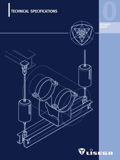
<strong>TECHNICAL</strong> <strong>SPECIFICATIONS</strong><br />
0<br />
PRODUCT<br />
GROUP
<strong>TECHNICAL</strong><br />
<strong>SPECIFICATIONS</strong><br />
CONTENTS PAGE<br />
1. Standard supports ________________________________________________ 0.1<br />
1.1 Requirements ____________________________________________________ 0.1<br />
1.2 Definition________________________________________________________ 0.1<br />
2. <strong>LISEGA</strong> standard supports _________________________________________ 0.1<br />
2.1 Scope___________________________________________________________ 0.1<br />
2.2 Design features __________________________________________________ 0.1<br />
2.3 Principle of the optimum design type________________________________ 0.2<br />
3. <strong>LISEGA</strong> modular system ___________________________________________ 0.2<br />
3.1 Fundamentals ____________________________________________________ 0.2<br />
3.2 Scope___________________________________________________________ 0.2<br />
3.3 Product groups___________________________________________________ 0.2<br />
3.4 Load groups _____________________________________________________ 0.2<br />
3.5 Permissible loads_________________________________________________ 0.3<br />
3.6 Travel ranges ____________________________________________________ 0.6<br />
3.7 Type designations ________________________________________________ 0.6<br />
3.8 Type designation system __________________________________________ 0.7<br />
4. Standards and calculations_________________________________________ 0.9<br />
5. Materials ________________________________________________________ 0.9<br />
6. Qualification levels for standard and nuclear application________________ 0.9<br />
7. Welding ________________________________________________________ 0.10<br />
8. Surface treatment _______________________________________________ 0.10<br />
8.1 Standard coating systems_________________________________________ 0.10<br />
8.2 Standard surface protection acc. to products ________________________ 0.11<br />
8.3 Extended surface protection_______________________________________ 0.11<br />
8.4 Extended surface protection acc. to products ________________________ 0.12<br />
8.5 Surface protection in extremely aggressive atmospheres _________________ 0.12<br />
9. Connection dimensions___________________________________________ 0.12<br />
9.1 Installation dimension E __________________________________________ 0.12<br />
9.2 Regulation of the total installation length ___________________________ 0.13<br />
10. Operational behavior_____________________________________________ 0.13<br />
10.1 Function _______________________________________________________ 0.13<br />
10.2 Spring relaxation ________________________________________________ 0.14<br />
11. Quality assurance________________________________________________ 0.14<br />
11.1 Fundamentals ___________________________________________________ 0.14<br />
11.2 Quality management _____________________________________________ 0.14<br />
11.3 International qualifications ________________________________________ 0.14<br />
11.4 Tests and qualifications __________________________________________ 0.15<br />
11.5 Suitability tests acc. to KTA 3205.3 and VGB R 510 L _________________ 0.15<br />
12. Shipment_______________________________________________________ 0.16<br />
13. Warranty _______________________________________________________ 0.16<br />
14. Technical modifications___________________________________________ 0.16<br />
0 <strong>TECHNICAL</strong><br />
0<br />
<strong>SPECIFICATIONS</strong><br />
1<br />
2<br />
3<br />
4<br />
5<br />
6<br />
7<br />
8<br />
9<br />
0.0
0.1<br />
<strong>TECHNICAL</strong><br />
<strong>SPECIFICATIONS</strong><br />
The products outlined in<br />
this catalog - STANDARD<br />
SUPPORTS 2010 - are fully<br />
in line with the latest developments<br />
in support technology<br />
and satisfy general<br />
requirements for plant<br />
installation at the highest<br />
level. For the general<br />
design of <strong>LISEGA</strong> standard<br />
supports, uniform criteria<br />
are applied. They are<br />
described in the following<br />
<strong>TECHNICAL</strong> <strong>SPECIFICATIONS</strong><br />
and are binding for the<br />
contents of this catalog.<br />
Componentrelated features<br />
are outlined in the corresponding<br />
sections of the<br />
product groups and in the<br />
type data sheets<br />
Unless expressly agreed<br />
otherwise, the stipulations<br />
in the catalog STANDARD<br />
SUPPORTS 2010 apply to<br />
all our shipments.<br />
1. STANDARD SUPPORTS<br />
1.1 Requirements<br />
For the support of industrial piping systems,<br />
the use of standard supports is regarded as<br />
well proven, up-to-date technology.<br />
Only a correspondingly high level of standardization<br />
in support components can adequately<br />
satisfy the justifiable demand for products<br />
that are technically top-class and economically<br />
attractive at the same time. The complex<br />
requirements for modern pipe supports are:<br />
➜ reliable functioning<br />
➜ maintenance-free operation<br />
➜ low unit prices<br />
➜ simple planning with DP systems<br />
➜ instant availability<br />
➜ economical installation strategy<br />
➜ easy to install designs<br />
➜ supplementary service benefits<br />
1.2 Definition<br />
Standard supports must fulfill the following<br />
criteria:<br />
➜ component shapes are uniform and<br />
designed for optimum exploitation<br />
of material<br />
➜ units are compatible regarding connecting<br />
dimensions and loading capacity<br />
➜ units are cataloged and clearly identifiable<br />
by a designation system<br />
➜ components are manufactured in<br />
series production<br />
➜ components comply with the relevant<br />
standards and international regulations<br />
➜ functional capacity, suitability and<br />
durability of the units is well proven<br />
➜ components are certified and<br />
approved for use<br />
The relevant codes for pipe supports in<br />
German plant construction (power plants),<br />
VGB guideline R 510 L, require the preferential<br />
use of standard supports and define the<br />
criteria as follows:<br />
“Standard supports are pipe support components,<br />
the construction of which, in form<br />
and dimensions as well as in the design<br />
data relating to loading capacity, is certificated<br />
and cataloged, and which are manufactured<br />
according to firmly established, reproducible<br />
procedures, e.g. series production”.<br />
2. <strong>LISEGA</strong> STANDARD SUPPORTS<br />
2.1 Scope<br />
At <strong>LISEGA</strong>, standard supports form the basis<br />
of a comprehensive performance package.<br />
A complete program from more than 8000<br />
standardized components thereby covers all<br />
operational loads, temperatures and travel<br />
ranges normally met in piping systems in<br />
industrial plant construction:<br />
➜ 1200°F operating temperature for<br />
pipe clamps and clamp bases<br />
➜ 90 kips nominal load for all mainly<br />
statically determined components<br />
➜ 224 kips nominal load for rigid struts<br />
and standard shock absorbers<br />
➜ 1124 kips design load for large bore<br />
shock absorbers<br />
➜ 36 inch travel range for constant hangers<br />
➜ 16 inch travel range for spring hangers<br />
2.2 Design features<br />
Specially developed components are available<br />
for the various support functions. In the<br />
design and construction of the units, fundamental<br />
design principles have been taken<br />
into consideration:<br />
➜ symmetrical design shapes<br />
➜ compact installation dimensions<br />
➜ especially reliable function principles<br />
➜ extra wide adjustment ranges<br />
➜ fully compatible load ranges and<br />
connection dimensions<br />
➜ favorable performance/weight ratios<br />
➜ integrated installation aids
In addition, <strong>LISEGA</strong> hangers feature only one<br />
upper attachment point. As a result, and due<br />
also to the compact and symmetrical design<br />
shape, the load transfer free of moments to<br />
the connecting elements is ensured and<br />
simple installation enabled. The operational<br />
position of the moving parts (hangers,<br />
supports and shock absorbers) can be read<br />
directly off a travel scale. Load adjustment<br />
of the constant hangers and supports can be<br />
modified at all times, also in the installed<br />
condition under load. Hangers and supports<br />
can be blocked in any travel position.<br />
2.3 Principle of the optimum design type<br />
For the design of support components, optimum<br />
coverage of the specific support function<br />
is the decisive factor. For each function<br />
only one component is therefore required,<br />
namely, the optimum one for the purpose.<br />
The project engineer is spared costly selection<br />
from a series of alternative solutions. This<br />
not only facilitates application but also<br />
increases safety. Above and beyond this, it<br />
is a prerequisite for the rational application<br />
of standardized construction on the principle<br />
of the modular system.<br />
➜ There’s only ONE best solution!<br />
3. <strong>LISEGA</strong> MODULAR SYSTEM<br />
3.1 Fundamentals<br />
The cost of pipe supports is a major element<br />
in the total cost of a piping system.<br />
The cost of the supports is the accumulated<br />
total cost arising from:<br />
➜ project management (processing)<br />
➜ design and engineering work<br />
➜ use of materials (components) as well as<br />
➜ installation work<br />
The pipe supports are almost always critical<br />
for the commissioning deadline and can,<br />
through delayed delivery, cause incalculable<br />
extra costs. The aim of <strong>LISEGA</strong> product strategy<br />
is to forge, out of all the cost factors involved,<br />
the common cost minimum for the<br />
user in the sense of the economic principle.<br />
The <strong>LISEGA</strong> modular system is specially targeted<br />
towards this efficiency. The standardization<br />
of components forms the foundation and<br />
is the precondition for rational series production,<br />
dependable quality, systematic warehousing<br />
and computer assisted application. With<br />
the LICAD design system and corresponding<br />
logistics, significant rationalization effects<br />
can be achieved in engineering, design and<br />
installation.<br />
3.2 Scope<br />
The standardization at <strong>LISEGA</strong> extends beyond<br />
the components to their systematic interaction.<br />
To this end, load and travel distribution<br />
as well as function and connections<br />
are meaningfully coordinated.<br />
In this way the <strong>LISEGA</strong> standard support<br />
program has been developed as a functional<br />
modular system with logical linking. The individual<br />
units form modules therein and are<br />
compatible regarding loads and connections.<br />
This enables the formation of meaningful combinations<br />
to produce support configurations<br />
fulfilling all requirements. The large selection<br />
of components makes adaptation possible to<br />
widely differing support and application<br />
situations.<br />
3.3 Product groups<br />
The standardized units are divided into 7<br />
product groups according to their basic modes<br />
of function (see diagram, page 0.3, and table,<br />
Standardized Components, page 0.4).<br />
3.4 Load groups<br />
To guarantee compatible loads in unit combinations,<br />
the load spectrum is split into<br />
fixed load groups.<br />
Within a load group (nominal load), all components<br />
feature uniform load limits and stress<br />
safety characteristics. The connection shapes<br />
of the units (threads - either metric or UNC<br />
according to market area - or pin diameters)<br />
are uniform within a group and thus compatible.<br />
Components of different product groups<br />
can therefore be connected only within a uniform<br />
load group to safe load chains and the<br />
faulty combination of different load groups<br />
is precluded. As all units in a load group are<br />
designed uniformly regarding strength, the<br />
stresses on a complete chain of components<br />
0<br />
The economic principle:<br />
= from the least possible<br />
effort the maximum<br />
possible profit<br />
–––––––––––––––––––––––<br />
= Total Cost Minimum/TCM<br />
=====================<br />
Product groups<br />
+ load groups<br />
+ travel ranges<br />
+ connection compatibility<br />
––––––––––––––––––––––<br />
= Modular System<br />
===================<br />
Modular System<br />
+ CAD design<br />
+ DP logitic systems<br />
––––––––––––––––––––––<br />
= High tech application<br />
===================<br />
0.2
0.3<br />
are uniformly determined.<br />
For permissible stresses, a difference is made<br />
between statically and dynamically determined<br />
components. The units in product groups 1,<br />
2, 4, 5, 6 and 7 are stressed in only one<br />
load direction (statically or quasistatically)<br />
and are considered to be statically determined<br />
components. The components in Product<br />
Group 3, as well as their accessories, are<br />
loaded in alternating directions and are therefore<br />
regarded as dynamically determined<br />
components.<br />
3.5 Permissible loads<br />
The permissible loads for components,<br />
arranged in matrix form according to load<br />
pipe surrounding<br />
components<br />
spring<br />
hangers<br />
structural<br />
attachment elements<br />
CONNECTING THREADS<br />
Ø CONNECTING BOLTS<br />
constant<br />
hangers<br />
pipe bearing and<br />
saddle components<br />
load & connection<br />
compatibility<br />
dynamically<br />
loaded components<br />
design development<br />
tools<br />
LOAD GROUPS<br />
NOMINAL LOADS (lbs)<br />
threaded connecting<br />
components<br />
groups and load cases, are set out in the<br />
<strong>LISEGA</strong> load tables (see page 0.5). The definition<br />
of load cases is regulated according to<br />
ASME III, Div. 1 Subsection NF, ASME B<br />
31.1/MSS SP58 and DIN 18800, VGB-R 510<br />
L, KTA 3205.<br />
The load table applies uniformly to all components<br />
in the <strong>LISEGA</strong> modular system and<br />
to other <strong>LISEGA</strong> units systematically connected<br />
to it, e.g. integral special designs (see load<br />
table, page 0.5).
Product<br />
group<br />
1<br />
2<br />
3<br />
4<br />
5<br />
6<br />
7<br />
Standardized components<br />
Group Unit Unit<br />
designation type designation<br />
Constant 11 constant hanger<br />
hangers 12-14 multi-cell constant hanger<br />
16 constant support<br />
16 angulating const. support<br />
17 servo hanger<br />
71 support<br />
79 const. hanger, trapeze<br />
Spring 20 articulated spring support<br />
hangers 21 spring hanger<br />
22 heavy duty spring hanger<br />
25 spring hanger, seated<br />
26 heavy d. spr. hang., seated<br />
27 sway brace<br />
28 heavy duty spring support<br />
29 variable spring support<br />
72 base plate<br />
79 spring hanger trapeze<br />
Dynamically 30 shock absorber<br />
loaded 31 large bore shock absorber<br />
components 32 energy absorber<br />
33 installation extension<br />
35 weld-on bracket<br />
36-37 dynamic pipe clamp<br />
39 rigid strut<br />
Pipe<br />
40 U-bolt<br />
surrounding 41 weld-on lug<br />
components 42-44 horizontal clamp<br />
45-48 riser clamp<br />
49 clamp base, lift-off restraints<br />
Pipe<br />
51 cylinder roller bearing<br />
bearings 52 double taper roller bearing<br />
and saddle 53 double cylinder roller bear.<br />
components 54 weld-on pipe saddle<br />
54 pipe saddle w. pipe clamp<br />
54 support tray<br />
55 lift-off restraint<br />
56 insulated pipe bearing<br />
57 weld-on pipe shoe<br />
58 stanchion<br />
58 elbow pad<br />
Threaded 60 eye nut<br />
connecting 61 clevis<br />
elements 62 turnbuckle<br />
63 hexagon nut<br />
64 rod coupling<br />
65 tie rod L/R<br />
66 tie rod<br />
67 threaded rod / stud bolt<br />
Structural 73 weld-on clevis<br />
attachment 74 weld-on pl. w. spher. wash.<br />
elements 75 weld-on eye nut<br />
76 beam adapter<br />
77 connecting plate<br />
78 beam clamp<br />
79 trapeze<br />
Load<br />
group<br />
C<br />
D<br />
1<br />
2<br />
3<br />
4<br />
5<br />
6<br />
7<br />
8<br />
9<br />
10<br />
20<br />
30<br />
40<br />
50<br />
Statically defined components<br />
Product group 1, 2, 4, 6, 7<br />
Nominal<br />
load [lbs]<br />
70<br />
141<br />
281<br />
562<br />
1125<br />
2250<br />
4495<br />
8990<br />
13490<br />
17985<br />
22480<br />
35970<br />
44960<br />
53955<br />
67400<br />
90000<br />
Ø Connection<br />
thread<br />
3/ 8<br />
3/ 8<br />
1/ 2<br />
1/ 2<br />
5/ 8<br />
3/ 4<br />
1<br />
11/ 4<br />
11/ 2<br />
13/ 4<br />
2<br />
21/ 4<br />
21/ 2<br />
23/ 4<br />
3<br />
31/ 4<br />
Wrench<br />
size<br />
11/ 16<br />
11/ 16<br />
7/ 8<br />
7/ 8<br />
11/ 16<br />
11/ 4<br />
15/ 8<br />
2<br />
23/ 8<br />
23/ 4<br />
31/ 8<br />
31/ 2<br />
37/ 8<br />
41/ 4<br />
45/ 8<br />
5<br />
3.5.1 Static components<br />
The nominal load is used for the determination<br />
of load groups. For the statically determined<br />
components in Product Groups 1, 2,<br />
4, 6, 7, the nominal load corresponds to<br />
the max. adjustment load of the spring elements,<br />
such as spring hangers and constant<br />
hangers. The maximum permissible hot load<br />
(load case H) lies considerably higher than<br />
the nominal load when components are<br />
used as rigid supports, and is tied to the<br />
load capacity of the connection threads.<br />
<strong>LISEGA</strong> threaded rods should therefore only<br />
be replaced in kind (see page 6.5, 6.6).<br />
Spring and constant hangers in the blocked<br />
position also count as rigid supports, whereby<br />
for cold loads in hydrostatic tests (short<br />
duration) the emergency loads (level C) can<br />
be exploited.<br />
For Product Group 4 (pipe connections) a limited<br />
area of overlapping in the load groups<br />
is foreseen, due to the temperature-related,<br />
variable spectrum of loading capacities. Data<br />
on the permissible loads relating to the respective<br />
operating temperature are set out for<br />
pipe connection components in the individual<br />
type data sheets.<br />
For Product Group 5 see 3.5.5, page 0.5.<br />
Ø<br />
Pin<br />
3/ 8<br />
3/ 8<br />
1/ 2<br />
1/ 2<br />
5/ 8<br />
13/ 16<br />
1<br />
15/ 16<br />
19/ 16<br />
13/ 4<br />
2<br />
23/ 8<br />
23/ 4<br />
23/ 4<br />
31/ 8<br />
31/ 2<br />
0<br />
Dyn. defined components<br />
Product group 3<br />
Load<br />
group<br />
–<br />
–<br />
1<br />
2<br />
3<br />
4<br />
5<br />
6<br />
7<br />
8<br />
9<br />
10<br />
20<br />
30<br />
40<br />
50<br />
Nominal<br />
load [lbs]<br />
–<br />
–<br />
675<br />
900<br />
1800<br />
4000<br />
10350<br />
22450<br />
44900<br />
78600<br />
123500<br />
224000<br />
448000<br />
670000<br />
900000<br />
1124000<br />
Ø<br />
Pin<br />
–<br />
–<br />
0.39<br />
0.39<br />
0.47<br />
0.59<br />
0.78<br />
1.18<br />
1.96<br />
2.36<br />
2.75<br />
3.93<br />
4.72<br />
5.51<br />
6.29<br />
7.08<br />
3.5.2 Dynamic components<br />
For dynamically determined<br />
units, the stipulation of the<br />
nominal loads follows from<br />
the meaningful division of<br />
the standardizable load<br />
spectrum. Here, the nominal<br />
load corresponds at the<br />
same time to the operating<br />
load for load event level<br />
A/B (ASME).<br />
As these components are<br />
generally used to guard<br />
against emergencies, the<br />
load event level C (ASME),<br />
possibly even level D, is<br />
usually adopted as the max.<br />
expected operating load.<br />
In each case the project<br />
engineer’s instructions<br />
apply.<br />
0.4
Max. operating load for spring<br />
and constant hangers corresponding<br />
to max. load on load springs.<br />
Permissible loads according to<br />
the design criteria for US code<br />
MSS SP 58 (ASME B 31.1).<br />
All loads are to be included<br />
hereunder that can possibly result<br />
from the normal operation of the<br />
plant, including start-up and shutdown,<br />
load tolerances and hydrostatic<br />
tests.<br />
Loads outside normal operation<br />
are grouped hereunder, possibly<br />
also hydrostatic tests. In each case<br />
a final inspection of the whole<br />
support arrangement is recommended.<br />
For the given loads, the yield<br />
stress of components can be<br />
reached. In each case replacement<br />
is recommended.<br />
Hereunder all dynamic loads<br />
are to be included that can possibly<br />
result from plant operation,<br />
including pressure shock forces<br />
from valve operation, and perhaps<br />
operating basis earthquakes (OBE).<br />
Hereunder all the dynamic<br />
loads are grouped which lie outside<br />
normal operation, as for<br />
example safe shutdown earthquakes<br />
(SSE). In each case a final inspection<br />
of the whole support arrangement<br />
is recommended.<br />
Dynamic loads from faulted<br />
conditions. For the given loads,<br />
the yield stress of components<br />
can be reached. Replacement is<br />
recommended in each case.<br />
Load groups 1 and 2 are load<br />
and connection compatible, whereby<br />
load group 1 applies to the<br />
smallest shock absorber and load<br />
group 2 to the corresponding<br />
rigid struts and weld-on brackets.<br />
0.5<br />
3.5.3 Max. permissible loads (lbs) for statically determined components<br />
Load<br />
group<br />
C<br />
D<br />
1<br />
2<br />
3<br />
4<br />
5<br />
6<br />
7<br />
8<br />
9<br />
10<br />
20<br />
30<br />
40<br />
50<br />
Load<br />
group<br />
1<br />
<br />
2<br />
3<br />
4<br />
5<br />
6<br />
7<br />
8<br />
9<br />
10<br />
20<br />
30<br />
40<br />
50<br />
Normal operation Emergency Faulted condition <br />
Nominal<br />
load <br />
Level A/B<br />
176°F<br />
Upset<br />
302°F<br />
Level C<br />
176°F 302°F<br />
Level D<br />
176°F 302°F<br />
70 157 179 157<br />
247 224<br />
314 292<br />
141 382 562 494<br />
741 651<br />
966 854<br />
281 629 944 831 1258 1124<br />
1618 1438<br />
562 990 1505 1350 2025 1800<br />
2990 2700<br />
1125 1910 2540 2270 3370 3010<br />
4990 4495<br />
2250 3150 5240 4700 6970 6250<br />
9215 8320<br />
4495 6070 7645 6745 10340 9215<br />
13710 12365<br />
8990 9665 12590 11240 16635 14835<br />
21575 19330<br />
13490 14160 18660 16635 24275 21800<br />
31465 28320<br />
17985 19110 25620 22925 33715 30340<br />
43825 39330<br />
22480 25180 33935 30340 44050 39555<br />
57310 51690<br />
35970 40015 49895 44725 66300 59555<br />
85625 77085<br />
44960 48330 66750 59780 88700 79780 115065 103605<br />
53955 60700 76410 68545 101580 91245 131470 118210<br />
67400 71940 85400 76400 113500 101200 146100 131500<br />
90000 90000 110100 98900 146100 131500 188800 169700<br />
3.5.4 Max. permissible loads (lbs) for dynamically determined components, Product Group 3<br />
675<br />
900<br />
1800<br />
4000<br />
10350<br />
22450<br />
44900<br />
78600<br />
123500<br />
224000<br />
448000<br />
670000<br />
900000<br />
1124000<br />
Normal (Fn)/Upset <br />
Level A/B<br />
176°F 302°F<br />
650<br />
875<br />
1680<br />
3710<br />
9900<br />
21200<br />
39300<br />
76100<br />
120000<br />
210000<br />
426000<br />
640000<br />
854000<br />
1067000<br />
900<br />
1190<br />
2380<br />
5380<br />
13700<br />
31000<br />
60000<br />
106000<br />
165000<br />
300000<br />
597000<br />
898000<br />
1195000<br />
1495000<br />
3.5.5 Product Group 5<br />
The units in Product Group 5, pipe clamp<br />
bases for cold piping systems, cryogenic<br />
systems, as well as roller bearings and pipe<br />
saddles, are regarded as statically determined,<br />
but are not directly connected with the hanger<br />
supports. As they are comparable with secondary<br />
steel components, they constitute a special<br />
group. The nominal load corresponds<br />
here to the max. operational load according<br />
to level A.<br />
Emergency <br />
Level C<br />
176°F 302°F<br />
850<br />
1150<br />
2180<br />
4950<br />
13150<br />
28000<br />
53500<br />
95000<br />
160000<br />
277000<br />
566000<br />
853000<br />
1135000<br />
1420000<br />
1160<br />
1550<br />
3070<br />
6960<br />
17300<br />
40400<br />
75500<br />
147000<br />
210000<br />
391000<br />
773000<br />
1159000<br />
1545000<br />
1930000<br />
Faulted condition <br />
Level D<br />
176°F 302°F<br />
permissible loads (lbs)<br />
1120<br />
1500<br />
2800<br />
6400<br />
16700<br />
36400<br />
67500<br />
132000<br />
205000<br />
362000<br />
734000<br />
1101000<br />
1465000<br />
1830000<br />
3.5.6 Max. permissible loads (lbs) for<br />
Product Group 5<br />
Normal load H 900 1800 3600 7870 13500 27000<br />
Emerg. load HZ 1235 2470 4945 10560 18000 36000
3.6. Travel ranges<br />
3.6.1 Travel ranges of static components<br />
Moving parts such as spring and constant<br />
hangers are divided into travel ranges corresponding<br />
to the usable spring travel of the<br />
standard springs employed.<br />
The appropriate travel range in each case is<br />
marked by the 4th digit of the type designation<br />
according to the following table.<br />
Constant hanger<br />
0 - 6<br />
Travel range<br />
inch [150mm]<br />
0- 12 inch [300mm]<br />
0- 18 inch [450mm]<br />
0 - 24 inch [600mm]<br />
0- 291/ 2 inch [750mm]<br />
0 - 351/ 2 inch [900mm]<br />
Designation No.<br />
1. .2 . .<br />
1. .3 . .<br />
1. .4 . .<br />
1. .5 . .<br />
1. .6 . .<br />
1. .7 . .<br />
Spring hanger<br />
Travel range Designation No.<br />
0 - 2 inch [50mm]<br />
2. .1 . .<br />
0- 4 inch [100mm]<br />
2. .2 . .<br />
0- 8 inch [200mm]<br />
2. .3 . .<br />
0 - 12 inch [300mm]<br />
2. .4 . .<br />
0- 16 inch [400mm]<br />
2. .5 . .<br />
For spring hangers and supports (Product<br />
Group 2) the springs are already installed<br />
preset to approx. 1/3 of their nominal load.<br />
The initial load follows from this and the<br />
spring travel is correspondingly reduced.<br />
3.6.2 Shock absorber travel ranges<br />
The maximum strokes of <strong>LISEGA</strong> shock absorbers<br />
are divided into economical stroke<br />
ranges as standard, and are so designated<br />
in the 4th digit of the type designation according<br />
to the following table.<br />
Stroke<br />
5 7/ 8 inch [150mm]<br />
11 3/ 4 inch [300mm]<br />
15 3/ 4 inch [400mm]<br />
19 3/ 4 inch [500mm]<br />
23 5/ 8 inch [600mm]<br />
29 1/<br />
Shock absorber<br />
Type<br />
30<br />
30<br />
30<br />
30<br />
30<br />
2 inch [750mm] 30<br />
4 inch [100mm] 30/31<br />
8 inch [200mm] 30/31<br />
Design. No.<br />
. . .2 . .<br />
. . .3 . .<br />
. . .4 . .<br />
. . .5 . .<br />
. . .6 . .<br />
. . .7 . .<br />
. . .8 . .<br />
. . .9 . .<br />
3.7 Type designation<br />
All components can be clearly identified via<br />
coded type designations. Six digits contain<br />
all the necessary information required.<br />
The type designation system facilitates the<br />
use of modern information technology and<br />
enables the unrestricted application of the<br />
modular system in current CAD programs.<br />
3.7.1 Example of constant hanger, type 11<br />
115325<br />
3.7.2 Example of clamp base, type 49<br />
495185<br />
3.7.3 Example of rigid strut, type 39<br />
396254<br />
1985<br />
standard<br />
travel range 3/0-12 inch<br />
load group 5/FN 4495 lbs<br />
single cell<br />
constant hanger<br />
high design, welded<br />
13CrMo4-5, Nuclear spec.<br />
pipe diameter 20 inch<br />
clamp base<br />
pipe conn. part<br />
standard spec.<br />
length 98 1/ 4 inch<br />
load group 6 / FN 22480 lbs<br />
rigid strut<br />
Complete integrated<br />
application of 8000<br />
components possible<br />
through clearcut type<br />
designation key!<br />
0<br />
0.6
3.8 Type designation system<br />
The <strong>LISEGA</strong> type designations can be decoded using the<br />
following tables.<br />
3.8.1 Constant hangers and constant supports<br />
Digit<br />
1<br />
Product<br />
group<br />
1<br />
Digit<br />
1<br />
Product<br />
group<br />
2<br />
0.7<br />
Digit<br />
2<br />
Model<br />
1= constant<br />
hanger<br />
6= constant<br />
support/<br />
angulating<br />
constant<br />
support<br />
2= CH<br />
2-cell coupl.<br />
3= CH<br />
3-cell coupl.<br />
4= CH<br />
4-cell coupl.<br />
7= servo<br />
hanger<br />
Digit<br />
3<br />
Load group<br />
C= 3 / 8UNC-70lbs<br />
D= 3 / 8UNC-141lbs<br />
1= 1 / 2UNC-281lbs<br />
2= 1 / 2UNC-562lbs<br />
3= 5 / 8UNC-1125lbs<br />
4= 3 / 4UNC-2250lbs<br />
5=1UNC-4495lbs<br />
6=1 1 / 4UNC-8990lbs<br />
7=1 1 / 2UNC-13490lbs<br />
8=1 3 / 4UNC-17985lbs<br />
9=2UNC-22480lbs<br />
8=2 1 / 4UNC-35970lbs<br />
9=2 1 / 2UNC-44960lbs<br />
8=2 3 / 4UNC-53955lbs<br />
9=3UNC-67400lbs<br />
8=3UNC-71940lbs<br />
9=3 1 / 4UNC-90000lbs<br />
5=1UNC-4495lbs<br />
6=1 1 / 4UNC-8990lbs<br />
7=1 1 / 2UNC-13490lbs<br />
8=1 3 / 4UNC-17985lbs<br />
9=2UNC-22480lbs<br />
Digit<br />
4<br />
Travel<br />
range<br />
2=6inch<br />
3=12inch<br />
4=18inch<br />
5=24inch<br />
6=30inch<br />
7=36inch<br />
2=6inch<br />
3=12inch<br />
3.8.2 Spring hangers and spring supports<br />
Digit<br />
2<br />
Model<br />
0= angul.<br />
spring supp.<br />
0= extens. f.<br />
type 20<br />
1= spring h.<br />
suspended<br />
5= spring h.<br />
seated<br />
7= sway brace<br />
7= extens. f.<br />
type 27<br />
9= spring sup.<br />
2= SH,<br />
suspended<br />
6= SH,<br />
seated<br />
8= spring sup.<br />
1=2 1 / 4UNC-35970lbs<br />
2=2 1 / 2UNC-44960lbs<br />
3=2 3 / 4UNC-53955lbs<br />
4=3UNC-67400lbs<br />
5=3 1 / 4UNC-90000lbs<br />
3.8.3 Dynamic components<br />
Digit<br />
1<br />
Product<br />
group<br />
3<br />
Digit<br />
2<br />
Model<br />
0= hydraulic<br />
shock absor.<br />
stand. design<br />
2= energy<br />
absorber<br />
3= extension<br />
1= hydraulic<br />
shock absor.<br />
large bore<br />
Digit<br />
5<br />
Field of<br />
application<br />
2=standard<br />
6=nuclear<br />
application<br />
STANDARD<br />
1=std. design<br />
2=angulated<br />
design<br />
NUCLEAR<br />
APPLICATION<br />
5=std. design<br />
6=ang. design<br />
3=standard<br />
7=nuclear<br />
application<br />
2=standard<br />
6=nuclear<br />
application<br />
Digit<br />
3<br />
Load group<br />
C= 3 / 8UNC-56lbs<br />
D= 3 / 8UNC-120lbs<br />
1= 1 / 2UNC-281lbs<br />
2= 1 / 2UNC-562lbs<br />
3= 5 / 8UNC-1125lbs<br />
4= 3 / 4UNC-2250lbs<br />
5=1UNC-4495lbs<br />
6=1 1 / 4UNC-8990lbs<br />
7=1 1 / 2UNC-13490lbs<br />
8=1 3 Digit<br />
4<br />
Digit<br />
5<br />
Travel Field of<br />
range application<br />
/ 4UNC-17985lbs<br />
9=2UNC-22480lbs<br />
1=2inch<br />
2=4inch<br />
3=8inch<br />
4=12inch<br />
5=16inch<br />
9=extens.<br />
f. type 20<br />
&. type 27<br />
1,2=standard<br />
5,6=nuclear<br />
application<br />
Digit<br />
3<br />
Load group<br />
1= 675lbs 4= 4000lbs<br />
2= 900lbs 5=10350lbs<br />
3= 1800lbs 6=22450lbs<br />
7= 44900lbs<br />
8= 78600lbs<br />
9= 123500lbs<br />
0= 224000lbs<br />
9= 123500lbs<br />
0= 224000lbs<br />
2= 448000lbs<br />
3= 670000lbs<br />
4= 900000lbs<br />
5= 1124000lbs<br />
Digit<br />
4<br />
Travel<br />
range<br />
2=5 7 /8inch<br />
3=11 3 /4inch<br />
4=15 3 /4inch<br />
5=19 3 /4inch<br />
8=4inch<br />
9=8inch<br />
8=4inch<br />
9=8inch<br />
Digit<br />
5<br />
Field of<br />
application<br />
1= standard<br />
5= nuclear<br />
application<br />
Digit<br />
6<br />
Prod.<br />
series<br />
5=1985<br />
9=1999<br />
Digit<br />
6<br />
Prod.<br />
series<br />
4=1994<br />
8=1978<br />
9=1999<br />
Digit<br />
6<br />
Prod.<br />
series<br />
2=2002<br />
3=1993<br />
6=1986<br />
8=1988<br />
at Type 32<br />
6=1996<br />
3.8.3 Dynamic components (cont.)<br />
Digit<br />
1<br />
Product<br />
group<br />
3<br />
3.8.4 Pipe clamps and clamp bases<br />
Digit<br />
1<br />
Product<br />
group<br />
4<br />
Digit<br />
2<br />
Model<br />
5= weld-on<br />
bracket<br />
6= dynamic<br />
pipe clamp<br />
with U-bolt<br />
7=dynamic<br />
pipe clamp<br />
with strap<br />
9= rigid<br />
struts<br />
Digit<br />
2<br />
Model<br />
1= weld-on<br />
lug<br />
horiz. clamp<br />
2=clevis clamp<br />
2=2 bolt clamp<br />
3=3 bolt clamp<br />
4= with Ubolt<br />
or strap<br />
riser clamps<br />
5=formed<br />
riser clamp<br />
6=riser cl., lugs<br />
8=riser clamp,<br />
trunnions<br />
9= clamp<br />
bases<br />
0= U-bolts<br />
9=Lift-off<br />
restraints for<br />
clamp bases<br />
Digit<br />
3<br />
Load group<br />
Digit<br />
3+4<br />
Pipe diameter in inch<br />
D9 = 141lbs<br />
29 = 562lbs<br />
39 = 1125lbs<br />
49 = 2250lbs<br />
01 = 0.84<br />
02 = 1.06<br />
03 = 1.33<br />
04 = 1.67<br />
05 = 1.90<br />
06 = 2.37<br />
07 = 2.87<br />
08 = 3.00<br />
09 = 3.50<br />
10 = 4.25<br />
11 = 4.50<br />
13 = 5.25<br />
14 = 5.50<br />
16 = 6.25<br />
17 = 6.63<br />
19 = 7.63<br />
22 = 8.63<br />
00=Lift-off<br />
restraints<br />
Digit<br />
4<br />
Travel<br />
range<br />
19= 675lbs 79= 44900lbs<br />
29= 900lbs 89= 78600lbs<br />
39= 1800lbs 99= 123500lbs<br />
49= 4000lbs 09= 224000lbs<br />
59= 10350lbs 20= 448000lbs<br />
69= 22450lbs<br />
pipe diameter<br />
in inch·2.54 [mm/10]<br />
2 = 900lbs<br />
3 = 1800lbs<br />
4 = 4000lbs<br />
5 = 10350lbs<br />
6 = 22450lbs<br />
7 = 44900lbs<br />
8 = 78600lbs<br />
9 = 123500lbs<br />
0 = 224000lbs<br />
middle<br />
installation<br />
dimension<br />
in inch/4<br />
59 = 4495lbs<br />
69 = 8990lbs<br />
79 = 13490lbs<br />
24 = 9.63<br />
26 = 10.50<br />
27 = 10.75<br />
32 = 12.75<br />
36 = 14.00<br />
37 = 14.50<br />
41 = 16.00<br />
42 = 16.50<br />
46 = 18.00<br />
51 = 20.00<br />
56 = 22.00<br />
61 = 24.00<br />
66 = 26.00<br />
71 = 28.00<br />
76 = 30.00<br />
81 = 32.00<br />
91 = 36.00<br />
Digit<br />
5<br />
Field of<br />
application<br />
1= standard<br />
5= nuclear<br />
application<br />
STANDARD<br />
1= up to 660°F<br />
2= up to 930°F<br />
3= up to 1040°F<br />
NUCLEAR<br />
APPLICATION<br />
6= up to 660°F<br />
7= up to 930°F<br />
8= up to 1040°F<br />
Digit<br />
5<br />
Field of<br />
application<br />
1= standard<br />
1= standard<br />
STANDARD<br />
1= up to 660°F<br />
2= up to 930°F<br />
3= up to 1040°F<br />
4= up to 1110°F<br />
5= up to 1200°F<br />
NUCLEAR<br />
APPLICATION<br />
6= up to 660°F<br />
7= up to 930°F<br />
8= up to 1040°F<br />
2= carbon<br />
steel<br />
4= stainless<br />
steel<br />
0=Lift-off<br />
restraints<br />
Digit<br />
6<br />
Prod.<br />
series<br />
1=1991<br />
3=1993<br />
6=1986<br />
9=1989<br />
1-6=<br />
U-bolts<br />
1-9=<br />
flat steel<br />
strap<br />
3-4=<br />
standard<br />
8-9=<br />
nuclear<br />
application<br />
Digit<br />
6<br />
Prod.<br />
series<br />
f. straight pipes,<br />
max. insul. thickn.<br />
1= 3 / 8inch<br />
2=4inch<br />
for pipe elbows<br />
R1.5OD<br />
max. insul. thickn.<br />
3,4= 3 / 8inch<br />
5,6=4inch<br />
depends<br />
on load<br />
range and<br />
design<br />
1=low<br />
2=medium<br />
3=low,<br />
welded<br />
4=medium,<br />
welded<br />
5=high,<br />
welded<br />
8=standard<br />
1-4=size
3.8.5 Roller bearings, cryogenic clamp bases<br />
Digit<br />
1<br />
Product<br />
group<br />
5<br />
Digit<br />
2<br />
Model<br />
1=cylinder<br />
roller bearings<br />
2=double taper<br />
roller bearings<br />
3=double cylinder<br />
roller bearings<br />
5=lift-off restr.<br />
f. roller bear.<br />
4=pipe saddle/<br />
support tray<br />
6= preinsulated<br />
pipes<br />
7= weld-on<br />
pipe bases<br />
8=<br />
stanchions<br />
8=elbow<br />
pads<br />
Digit<br />
3+4<br />
Load group<br />
Pipe diameter<br />
04= 900lbs<br />
08= 1800lbs<br />
12= 27000lbs<br />
16= 3600lbs<br />
35= 7870lbs<br />
60= 13500lbs<br />
01 = 0.84<br />
02 = 1.06<br />
03 = 1.33<br />
05 = 1.90<br />
06 = 2.37<br />
07 = 2.87<br />
08 = 3.00<br />
09 = 3.50<br />
10 = 4.25<br />
11 = 4.50<br />
13 = 5.25<br />
14 = 5.50<br />
16 = 6.25<br />
17 = 6.63<br />
19 = 7.63<br />
22 = 8.63<br />
24 = 9.63<br />
26 = 10.50<br />
27 = 10.75<br />
32 = 12.75<br />
36 = 14.00<br />
37 = 14.50<br />
41 = 16.00<br />
42 = 16.50<br />
46 = 18.00<br />
51 = 20.00<br />
56 = 22.00<br />
61 = 24.00<br />
66 = 26.00<br />
71 = 28.00<br />
76 = 30.00<br />
81 = 32.00<br />
91 = 36.00<br />
3.8.6 Connecting elements, connecting rods<br />
Digit<br />
1<br />
Product<br />
group<br />
6<br />
Digit<br />
2<br />
Model<br />
0=eye nut<br />
1=clevis<br />
2=turnbuckle<br />
4=rod<br />
coupling<br />
Digit<br />
3+4<br />
Load group<br />
D9 = 3 / 8UNC-141lbs<br />
29 = 1 / 2UNC-562lbs<br />
39 = 5 / 8UNC-1125lbs<br />
49 = 3 / 4UNC-2250lbs<br />
59 = 1UNC-4495lbs<br />
69 = 1 1 / 4UNC-8990lbs<br />
79 = 1 1 / 2UNC-13490lbs<br />
89 = 1 3 / 4UNC-17985lbs<br />
99 = 2UNC-22480lbs<br />
10 = 2 1 / 4UNC-35970lbs<br />
20 = 2 1 / 2UNC-44960lbs<br />
30 = 2 3 / 4UNC-53955lbs<br />
40 = 3UNC-67400lbs<br />
50 = 3 1 / 4UNC-90000lbs<br />
Digit<br />
5<br />
Field of<br />
application<br />
1=standard<br />
2=movable<br />
laterally<br />
1=weldable<br />
2=with pipe<br />
clamp<br />
3=support<br />
plate<br />
1=<br />
12inch long<br />
2,4,6=<br />
20inch long<br />
9=cold block<br />
1=standard<br />
1=<br />
stanchions<br />
2=telescopic<br />
stanchions<br />
3=standard<br />
Digit<br />
5<br />
Field of<br />
application<br />
2=standard<br />
6=nuclear<br />
4=hot dip<br />
galvanized<br />
Digit<br />
6<br />
Prod.series<br />
9=1989<br />
Insul. thickn.<br />
0=1inch<br />
1=1 1 / 2inch<br />
2=2inch<br />
3=3inch<br />
4=4inch<br />
5=5inch<br />
6=6inch<br />
7=7inch<br />
8=8inch<br />
9=10inch<br />
1= Cold<br />
Block<br />
1=from<br />
T-sections<br />
2=from<br />
C-sections<br />
1,2= for<br />
streight<br />
pipes<br />
3,4= for<br />
elbow<br />
R OD<br />
5,6= for<br />
elbow<br />
R1,5OD<br />
1=carbon steel<br />
2=stainless steel<br />
Digit<br />
6<br />
Prod.series<br />
2=1982<br />
5=1995<br />
8=1978<br />
9=1999<br />
3.8.6 Connecting elements, connecting rods (cont.)<br />
Digit<br />
1<br />
Digit<br />
2<br />
Digit<br />
3<br />
Product Model Load group<br />
group<br />
6<br />
3=hexag.<br />
nut<br />
5=tie rod<br />
left/right<br />
D=<br />
6=tie rod<br />
right/right<br />
7=stud bolt/<br />
threaded rod<br />
3 / 8UNC-141lbs<br />
2= 1 / 2UNC-562lbs<br />
3= 5 / 8UNC-1125lbs<br />
4= 3 / 4UNC-2250lbs<br />
5=1UNC-4495lbs<br />
6=11 / 4UNC-8990lbs<br />
7=11 / 2UNC-13490lbs<br />
8=13 Digit<br />
4<br />
Digit<br />
5<br />
Digit<br />
6<br />
Length Field of Prod.-<br />
application series<br />
9 (Model 3)<br />
1=not standardized<br />
1=standard<br />
6=nuclear<br />
application<br />
2=standard<br />
6=nuclear<br />
3=1993<br />
8=1978<br />
9=1999<br />
2=24inch<br />
3=48inch<br />
/ 4UNC-17985lbs 4=72inch<br />
9=2UNC-22480lbs 5=96inch<br />
6=120inch<br />
7=144inch<br />
10 = 2<br />
application<br />
4=hot dip<br />
galvanized<br />
1 / 4UNC-35970lbs<br />
20 = 21 / 2UNC-44960lbs<br />
30 = 23 / 4UNC-53955lbs<br />
40 = 3UNC-67400lbs<br />
50 = 31 0<br />
length<br />
not<br />
standardized{<br />
/ 4UNC-90000lbs<br />
3.8.7 Structural attachments and trapezes<br />
Digit<br />
1<br />
Product<br />
group<br />
7<br />
Digit<br />
2<br />
Model<br />
9=trapeze<br />
0=PTFE slide<br />
plate<br />
7=connecting<br />
plate<br />
Digit<br />
3<br />
Load group<br />
Digit<br />
4<br />
Function<br />
1= support<br />
for constant<br />
hanger<br />
C =<br />
2=base plate f.<br />
spring hanger<br />
3=weld-on clevis<br />
4=weld-on plate<br />
5=weld-on eye<br />
nut<br />
6=beam adapter<br />
and bolts<br />
8=beam clamp<br />
3 / 8UNC-70lbs<br />
D = 3 / 8UNC-141lbs<br />
1 = 1 / 2UNC-281lbs<br />
2 = 1 / 2UNC-562lbs<br />
3 = 5 / 8UNC-1125lbs<br />
4 = 3 / 4UNC-2250lbs<br />
5 = 1UNC-4495lbs<br />
6 = 11 / 4UNC-8990lbs<br />
7 = 11 / 2UNC-13490lbs<br />
8 = 13 / 4UNC-17985lbs<br />
9 = 2UNC-22480lbs<br />
10 = 21 / 4UNC-35970lbs<br />
20 = 21 / 2UNC-44960lbs<br />
30 = 23 / 4UNC-53955lbs<br />
40 = 3UNC-67400lbs<br />
50 = 31 2...7=<br />
travel<br />
range of<br />
constant<br />
hanger<br />
6-36inch<br />
1, 2, 3, 9=<br />
depends<br />
on design<br />
/ 4UNC-90000lbs<br />
Digit<br />
5<br />
Field of<br />
application<br />
STANDARD<br />
6= bolted<br />
7= loose<br />
NUCLEAR<br />
8= bolted<br />
9= loose<br />
1=standard<br />
5=nuclear<br />
application<br />
2=2 con- 2=const.hang.<br />
nections trapeze<br />
3=3 con- 1 and 2=<br />
nections<br />
1...3= travel<br />
spring hanger<br />
range of trapeze<br />
spring han- 3=rigid trapeze<br />
ger 2-8 inch<br />
3 rd to 6 th digits correspond to clamps to be coupled<br />
Digit<br />
6<br />
Prod.series<br />
5,9 =<br />
bracket 1x<br />
6 =<br />
bracket 2x<br />
7 =<br />
bracket 3x<br />
8 =<br />
bracket 4x<br />
1=1991/<br />
2001<br />
2=1982<br />
3=1993<br />
4=1994<br />
5=1985<br />
6=1996<br />
8=1978<br />
9=1989<br />
4, 6 and 9=<br />
U-sections<br />
7=<br />
L-sections<br />
0.8
Worldwide coverage<br />
of recognized codes<br />
and standards!<br />
Standardized selection<br />
of high temperature<br />
materials!<br />
0.9<br />
4. STANDARDS AND CALCULATIONS<br />
In design, stress and load calculations, as<br />
well as in manufacturing, the relevant German<br />
and international standards, technical regulations<br />
and codes are taken into account.<br />
The following codes apply:<br />
MSS SP 58 Pipe supports - material and design USA<br />
MSS SP 69 Pipe supports - applications USA<br />
ANSI ASME B31.1 Pressure piping systems USA<br />
ASME III Div.I - NF Supports for nuclear components USA<br />
VGB-R 510 L Standard supports Germany<br />
DIN 18800 Steelwork Germany<br />
KTA 3205.1/2/3 Nuclear regulations Germany<br />
AD-Merkblätter Working group for pressure vessels Germany<br />
TRD-Regel Techn. regulations, steam boilers Germany<br />
BS 3974 Pipe supports UK<br />
RCC-M Specifications for pipe supports France<br />
MITI 501 Technical regulations Japan<br />
JEAG 4601 Nuclear design regulations Japan<br />
5. MATERIALS<br />
Materials are exclusively used which correspond<br />
to ASTM material requirements and<br />
DIN or DIN-EN norms.<br />
5.1 Preferred materials for pipe connection parts<br />
S235JRG2<br />
S235JRG2<br />
S235JRG2<br />
S355J2G3<br />
S355J2G3<br />
S355J2G3<br />
P235T1<br />
P235G11TH<br />
16Mo 3<br />
13CrMo 4-5<br />
10CrMo 9-10<br />
X10CrMoVNb9-1<br />
X5CrNi 18-10<br />
42CrMoV 4<br />
X10CrMoVNb9-1<br />
21 CrMoV 5-7<br />
X22CrMoV12-1<br />
24CrMo 5<br />
6. QUALIFICATION LEVELS FOR STANDARD AND<br />
NUCLEAR APPLICATION<br />
Standard supports have the same function<br />
both in the conventional and in the nuclear<br />
field of application, and therefore do not<br />
The characteristic values of materials that all<br />
design calculations are based on are taken<br />
from the relevant standards and recognized<br />
technical codes.<br />
As a matter of principle, only materials of<br />
guaranteed strength properties are used for<br />
supporting components.<br />
EN<br />
Material<br />
Material-No. EN 10027-2 ASTM 660<br />
Temperature of medium in °F<br />
840 930 985 1040 1110 1200<br />
COMPONENTS<br />
1.0038 A 36<br />
x<br />
1.0038 A 515 Gr. 60 x<br />
1.0038 A 675 Gr. 55 x<br />
1.0570 A 675 Gr. 70 x<br />
1.0570 A 299<br />
x<br />
1.0570 A 516 Gr. 70 x<br />
1.0254 A 53 S Gr. A x<br />
1.0305 A 53 S Gr. A x<br />
1.5415 A 204<br />
x x x<br />
1.7335 A 387 Gr. 12 x x x x x<br />
1.7380 A 387 Gr. 22 x x x x x x<br />
1.4903 A 387 Gr. 91 Cl.II x x x x x x x<br />
1.4301 A 312 TP 304 x x x x<br />
MEANS OF CONNECTION<br />
1.7225 A 193 B7<br />
x<br />
A 193 B8<br />
x x x x x x x<br />
1.4903 A 182 F91 x x x x x x x<br />
1.7709<br />
x x x x x<br />
1.4923<br />
x x x x x x x<br />
1.7258 A 194 Gr. 2H x x x x x<br />
differ in design. Due to additional qualityassuring<br />
measures and materials with special<br />
certification, separate manufacture is however<br />
necessary.
In the field of nuclear application, all materials<br />
are traceable right through to the finished<br />
product via heat number restamping, and the<br />
components themselves are marked according<br />
to ASME and KTA regulations. In the<br />
type designation, the nuclear design is noted<br />
in the 5th digit (for struts, the 6th digit). The<br />
relevant component documentation relates<br />
to this and to the fabrication order number.<br />
In this catalog, the standard design, i.e. nonnuclear<br />
applications, provides the basis for<br />
the type designations. As the given functional<br />
data and unit dimensions are the same for<br />
nuclear applications, selection can also be<br />
made here with the help of the catalog.<br />
On planning or ordering, attention must however<br />
be paid to corresponding conformity of<br />
the type designations. The table showing the<br />
type designation system (3.8, page 0.7) can be<br />
consulted in this respect.<br />
7. WELDING<br />
All welding is carried out as gas metal arc<br />
welding - in special cases by stick welding.<br />
<strong>LISEGA</strong> holds certifications according to:<br />
➜ ASME III Div I NCA NPT stamp<br />
➜ DIN EN 729-2 by the German TÜV<br />
➜ AD-HPO, production and testing of<br />
pressure vessels, by the TÜV<br />
➜ DIN 18800 T7 Extended suitability<br />
certification for steelwork and bridge<br />
construction by the SLV, the training<br />
and testing institute for welding<br />
technology<br />
<strong>LISEGA</strong> welding inspection personnel are qualified<br />
according to ASME III NCA 4000 NF,<br />
DIN EN 719, AD HP3 and HP4. Nondestructive<br />
tests are carried out by testing<br />
staff qualified acc. to ASME IX and DIN EN<br />
473, level 2, and SNT-TC-1A, level II.<br />
Supporting connections are produced corresponding<br />
to the material group by qualified<br />
welders according to ASME IX or DIN EN<br />
287, part 1. The welding procedure is qualified<br />
according to ASME IX and DIN EN 288.<br />
8. SURFACE TREATMENT<br />
8.1 Standard coating systems<br />
The surfaces of <strong>LISEGA</strong> products are protected<br />
as standard from corrosive influences by high<br />
quality protection systems that are also suitable<br />
for external use in aggressive conditions<br />
(coastal, industrial and chemical areas).<br />
The following coating systems are applied<br />
to the different products:<br />
8.1.1 Primer coating<br />
Components that are either to be welded<br />
to existing structure in the plant or simply<br />
require higher quality transport protection are<br />
coated on a bright metal surface with weldable<br />
primer (thickness app. 1.18 mil [30µm],<br />
color reddish brown).<br />
8.1.2 Electrogalvanizing<br />
Spring hangers and supports up to load size<br />
9, as well as all threaded parts and special<br />
function parts, are electrogalvanized (zinc<br />
thickness app. 0.59 mil [15µm], yellow chromatized).<br />
UNC threaded parts are white chromatized.<br />
8.1.3 Paint coatings<br />
Constant hangers and supports and other<br />
products according to table 8.2 receive the<br />
following surface treatment:<br />
1. Steel grit blasting according to SP-6 or<br />
SP-10 for the U.S. and EN ISO 12944-4<br />
grade SA 2 1/2 for Europe.<br />
2. Undercoat of 1-component polyurethane<br />
zinc dust primer, dry film thickness 2.36 mil<br />
[60µm], approx. 62% zinc in solid state<br />
volume, color grey.<br />
3. Final coating of 2-component acrylic polyurethane<br />
paint, dry film thickness 2.36 mil<br />
[60µm], color RAL 5012, light blue.<br />
The total dry film thickness of the system<br />
amounts to approx. 4.72 mil [120µm].<br />
8.1.4 Hot dip galvanization<br />
Roller bearings, pipe saddles and cryogenic<br />
pipe clamp bases are hot dip galvanized as<br />
standard, zinc thickness approx. 2.36 mil<br />
[60µm].<br />
0<br />
Separate manufacture<br />
of products for nuclear<br />
applications for the<br />
traceability of<br />
qualified materials!<br />
0.10
Standardized procedures<br />
for surface protection for<br />
constant quality!<br />
0.11<br />
8.1.5 Stainless steel designs<br />
Shock absorbers and energy absorbers<br />
(E-Bars) are made entirely of non-corroding<br />
materials. Connecting parts are electrogalvanized<br />
according to 8.1.2.<br />
8.1.6 Cathodic immersion process (CIP)<br />
All <strong>LISEGA</strong> springs are given special treatment<br />
because of their distinctive functional<br />
8.2 Standard surface protection in order of products (corresp. to 8.1)<br />
Product Type<br />
Constant hangers, constant supports<br />
Support for constant hangers<br />
Spring hangers, sway braces<br />
Spring supports (incl. load group 9)<br />
Spring hangers<br />
Spring supports (from load group 10)<br />
Weld-on brackets<br />
Dynamic pipe clamps<br />
Rigid struts<br />
Shock absorber extensions<br />
U-bolts<br />
Weld-on lugs, pipe clamps<br />
Riser clamps, pipe clamp bases<br />
Cylinder roller bearings<br />
Taper roller bearings<br />
Pipe saddles/support tray<br />
Lift-off restraints<br />
Pipe clamp bases f. cryogenic appl.<br />
Weld-on pipe shoe<br />
Elbow pads<br />
Stanchions<br />
Eye nuts, clevises<br />
Turnbuckles, rod couplings<br />
Hexagonal nuts, tie rods<br />
Threaded rods, stud bolts<br />
Base plates, weld-on clevises<br />
Spherical washers, weld-on eye nuts<br />
Beam adapters<br />
Connection plates<br />
Beam clamps<br />
Trapezes<br />
11 - 17<br />
71<br />
21, 25, 27<br />
20, 29<br />
22, 26<br />
28<br />
35<br />
36, 37<br />
39<br />
33<br />
40<br />
41, 42, 43, 44,<br />
45, 46, 48, 49<br />
51, 53<br />
52<br />
54<br />
55<br />
56<br />
57<br />
58<br />
58<br />
60, 61<br />
62, 64<br />
63, 65<br />
66, 67<br />
72, 73<br />
74, 75<br />
76<br />
77<br />
78<br />
79<br />
8.3 Extended surface protection<br />
For applications in the open involving highly<br />
corrosive conditions, such as coastal sites or<br />
chemical plants, extra protection can be supplied,<br />
insofar as this has not already been<br />
provided as standard by hot dip galvanizing<br />
or special steel versions. The following coating<br />
systems are thereby applied:<br />
significance. The peeled surface of the springs<br />
is steel ball blasted and zinc-phosphated; subsequently<br />
a 2-component epoxy resin coating<br />
is applied via electroimmersion and then<br />
burnt in at approx. 392°F [200°C] (CIP).<br />
This highly sophisticated process has been<br />
adopted from the automobile industry.<br />
Primer<br />
acc. to 8.1.1<br />
x<br />
x<br />
x<br />
x<br />
x<br />
x<br />
x<br />
x<br />
x<br />
x<br />
Electrogalvanized<br />
acc. to 8.1.2<br />
x<br />
x<br />
x<br />
x<br />
x<br />
x<br />
x<br />
x<br />
Standard<br />
paint<br />
coating<br />
acc. to 8.1.3<br />
x<br />
x<br />
x<br />
x<br />
x<br />
x<br />
x<br />
Hot dip<br />
galvanized<br />
acc. to 8.1.4<br />
8.3.1 Electrogalvanization with additional<br />
coats of paint<br />
1. A barrier layer (dry film thickness 18 mil<br />
[30µm]) is applied to the galvanized surface<br />
acc. to 8.1.2.<br />
2. As a final layer, a 2-component acrylic<br />
polyurethane finish (dry film thickness 2.36<br />
mil [60µm], color RAL 5012 - light blue) is<br />
applied.<br />
x<br />
x<br />
x<br />
x<br />
x<br />
x
8.3.2 Extra paint layer<br />
Over the standard paint coating according to<br />
8.1.3, a third protective layer consisting of a<br />
2-component acrylic polyurethane coating is<br />
applied. Dry film thickness 2.36 mil [60µm],<br />
color RAL 5012 - light blue, total dry film<br />
thickness app. 7.085 mil [180µm].<br />
8.4 Extended surface protection in order of products acc. to 8.3<br />
Product Type Electrogalvanization with Extra paint coating<br />
add. coating acc. to 8.3.1 acc. to 8.3.2<br />
Constant hangers, constant supports<br />
Supports for constant hangers<br />
Spring hangers, sway braces<br />
Spring supp. (incl. load group 9)<br />
Spring hangers<br />
Spring supp. (from load group 10)<br />
Rigid struts<br />
Shock absorber extensions<br />
Eye nuts, clevises<br />
Turnbuckles, rod couplings<br />
Hexagon nuts, tie rods<br />
Threaded rods, stud bolts<br />
Trapezes<br />
11 - 17<br />
71<br />
21, 25, 27<br />
20, 29<br />
22, 26<br />
28<br />
39<br />
33<br />
60, 61,<br />
62, 64<br />
63, 65,<br />
66, 67<br />
79<br />
8.5 Surface protection in extremely<br />
aggressive atmospheres<br />
For applications in specially aggressive atmospheres,<br />
e.g. coastal areas, certain industrial<br />
gases or offshore, special measures are to be<br />
agreed on.<br />
9. CONNECTION DIMENSIONS<br />
9.1 Installation dimension E<br />
For the simple determination of minimum<br />
installation lengths, the installation dimension<br />
E is given for all components except the<br />
connecting rods (Product Group 6). This<br />
dimension comprises the installation length<br />
minus the engaging length of the connecting<br />
part. For load chains, the E therefore designates<br />
the complete rod section.<br />
Special product-related features are to be<br />
taken into account as follows:<br />
x<br />
x<br />
8.3.3 Hot dip galvanizing<br />
Hot dip galvanized surface, layer thickness<br />
approx. 2.36 mil [60µm], bolts approx.<br />
1.57 mil [40µm].<br />
8.3.4 Stainless steel<br />
For the connecting parts of shock absorbers,<br />
energy absorbers (E-Bars) and rigid struts,<br />
stainless steel designs can be supplied.<br />
x<br />
x<br />
x<br />
x<br />
x<br />
x<br />
x<br />
Hot dip galvanizing<br />
acc. to 8.3.3<br />
To determine the total length of the rods in<br />
a load chain, all the E dimensions are to be<br />
added together. The sum of these is then to<br />
be compared with the total installation length.<br />
If the resulting difference is greater than the<br />
sum of the engagement depths (X dimensions),<br />
the chain selected is appropriate for the total<br />
installation height.<br />
For load chains consisting solely of pin connections,<br />
the minimum installation dimension<br />
follows from the sum of all E dimensions.<br />
x<br />
x<br />
x<br />
x<br />
0<br />
Simple checks for<br />
installation possibilities<br />
through dimension “E” !<br />
0.12
Sensible devices on hand<br />
for readjusting installation<br />
lengths!<br />
0.13<br />
9.2 Regulation of the total installation<br />
length<br />
9.2.1 Turnbuckle function of the connecting<br />
threads<br />
For length adjustment in installation condition<br />
(adjustment of pipe installation position, actuation<br />
of loading), the lower connections in<br />
constant and spring hangers provide a turnbuckle<br />
function. This way, subsequent adjustment<br />
of the installation lengths (attachment<br />
rods) within a sufficient range is possible:<br />
➜ for constant hangers type 11,<br />
by 11 3 /4 inch [300mm]<br />
➜ for spring hangers type 21, by the<br />
adjustment possibility of a turnbuckle,<br />
type 62<br />
➜ for spring hangers type 22,<br />
by min. 5 1 /2 inch [140mm]<br />
➜ for spring hangers types 25 and 26,<br />
the load bearing rod is fed through the<br />
weld-on support tube and fixed with<br />
an adjustment nut. The adjustment can<br />
be made within the scope of the available<br />
threaded length of the rod.<br />
All connection threads are supplied as right<br />
hand threads.<br />
9.2.2 Spring supports<br />
For spring supports types 28 and 29, the<br />
installation height can be regulated by the<br />
support tube, functioning as a spindle independently<br />
of the presetting.<br />
The necessary load is actuated on installation<br />
by screwing the support tube upwards.<br />
9.2.3 Turnbuckle, type 62, tie rod, left<br />
hand/right hand thread, type 65<br />
For rigid hanging support arrangements with<br />
short installation lengths, a defined reserve<br />
length in the connection parts type 60 and<br />
61 usually enables sufficient length adjustment.<br />
For longer installation lengths, the use<br />
of a turnbuckle L/R, type 62, in conjunction<br />
with a tie rod L/R, type 65, is appropriate.<br />
For easy access, this combination should be<br />
arranged at the lower end of the load chain.<br />
9.2.4 Rigid struts, type 39<br />
The connections in rigid struts type 39 are<br />
supplied as left/right, with fine threading for<br />
length adjustment in the installation condition<br />
as standard.<br />
Flat faces on the body of the rigid struts enable<br />
simple adjustment with a wrench.<br />
10. OPERATIONAL BEHAVIOR<br />
10.1 Function<br />
Constant hangers type 1 are designed so that<br />
in theory no load deviation occurs over the<br />
whole range of action. The total deviation<br />
resulting from springs, bearing friction, and<br />
fabrication tolerances is held to within 5%<br />
in series production.<br />
The load adjustment follows with a level of<br />
accuracy of 2%.<br />
load F<br />
FN = nominal load<br />
F min = min. load (upwards)<br />
F max = max. load (downwards)<br />
SN = nominal travel (incl. reserve)<br />
For spring hangers and supports, the load<br />
alters linearly corresponding to the spring<br />
travel. The deviation of the spring force from<br />
theoretical values, resulting from spring hysteresis<br />
and fabrication tolerances, amounts to<br />
less than 5% within the ordered travel.<br />
load F<br />
operating load<br />
FN = nominal load<br />
SN = nominal travel (incl. reserve)<br />
S = operating travel<br />
travel s<br />
travel s
10.2 Spring relaxation<br />
Conventional helical coil springs under load,<br />
depending on time and temperature factors,<br />
lose part of their tension by relaxation (settling<br />
loss), a loss that is not inconsiderable.<br />
If no appropriate measures are taken, for<br />
constant and spring hangers this can in the<br />
long run lead to a reduction in adjusted ultimate<br />
load of more than 10%.<br />
In contrast to common practice, <strong>LISEGA</strong> only<br />
uses springs that, through special treatment,<br />
permit no settling loss of any significance.<br />
In these springs the settling loss normally to<br />
be expected is anticipated via the process of<br />
hot setting from a longer coil length, producing<br />
corresponding prerelaxation.<br />
Relaxation<br />
Shear stress<br />
Relaxation behavior of helical coil springs<br />
Cold set helical coil springs<br />
(values loosely based on DIN 2089)<br />
<strong>LISEGA</strong> hot set helical coil springs<br />
qualified by TÜV and VGB suitability tests<br />
(independent German authorities)<br />
11. QUALITY ASSURANCE<br />
11.1 Fundamentals<br />
Superior product quality has an important place<br />
among the fundamental company goals at<br />
<strong>LISEGA</strong> and also involves the activities of<br />
and relationships with our business partners.<br />
The organization and attitudes of those working<br />
in the company are correspondingly attuned<br />
to this aim. In a quality management<br />
program (QMP), special quality-assuring<br />
measures are prescribed. They are an integral<br />
part of order processing and embrace the<br />
whole <strong>LISEGA</strong> group.<br />
11.2 Quality management program, QMP<br />
The QMP is clearly laid out in a quality management<br />
manual, QMM, and regulates all the<br />
quality-assuring activities in the company.<br />
The QMM covers the organization as a whole,<br />
whereby the observance of rules is monitored<br />
by the independent quality management department<br />
QM. The QMM has been compiled<br />
according to international quality norms and<br />
standards and specifically takes into account<br />
the regulations according to ASME III - NCA<br />
3800 and NCA 4000 incl. NF as well as DIN<br />
EN ISO 9001 and KTA 1401.<br />
The QMM applies in principle to both the conventional<br />
and nuclear fields. The extent of<br />
monitoring of materials and tests, as well as<br />
the documentation, can in each case be<br />
exactly adapted to special requirements by the<br />
use of extended QA levels. All international<br />
requirements concerning nuclear applications<br />
can be covered. Corresponding qualifications<br />
are available and are regularly renewed.<br />
11.3 International qualifications<br />
Certification code<br />
DIN/EN/ISO 9001<br />
DIN/EN/ISO 9001<br />
ASME-III NCA 4000/NF<br />
(NPT-Stamp)<br />
ASME-III NCA 3800/NF<br />
Stamping agreement<br />
AD-Merkblatt HP 0; HP 3; HP 4<br />
Welding certification according to EN 729-2<br />
DIN 18800T7<br />
Major qualification certificate<br />
ASME III - NCA/NF; ASME IX<br />
SKIFS 1994:1<br />
ASME-III NF/NCA 3800;<br />
10CFR50 App. B; 10CFR21;<br />
N45.2; NQA1<br />
Certification No.<br />
Reg.Nr. 200550<br />
1996/5030<br />
N-2951<br />
QSC 552<br />
0121WO29784<br />
07-702-0194<br />
07-703-0080<br />
60317/62/9804<br />
No. 1606<br />
No. DNV 5477<br />
CEXO-99/00210<br />
0<br />
QMP and Processing<br />
constitute a single entity!<br />
Certifying body<br />
Lloyd’s Register QA<br />
L’AFAQ<br />
ASME Accreditation and<br />
Certification<br />
ASME Accreditation and<br />
Certification<br />
TÜV Nord e.V.<br />
(independent German<br />
authority)<br />
SLV-Hannover<br />
TRACTEBEL (Vincotte)<br />
DET NORSKE VERITAS<br />
NUPIC<br />
0.14
Proven operational safety<br />
and long life through type<br />
and suitability tests!<br />
0.15<br />
11.4 Tests and qualifications<br />
11.4.1 Raw material and material reception<br />
All materials used undergo receiving control<br />
by the quality management department. The<br />
materials used are qualified, corresponding<br />
to requirements by material tests according<br />
to ASME and DIN EN 10204.<br />
11.4.2 Monitoring of manufacture<br />
Manufacture is monitored via accompanying<br />
quality control according to the QM manual.<br />
In particular, for nuclear applications the<br />
quality-assuring requirements according to<br />
ASME III NF and KTA are fulfilled.<br />
11.4.3 Final inspection<br />
Before shipment, constant and spring hangers<br />
as well as shock absorbers undergo a function<br />
test on test benches by quality management<br />
personnel. The tests are carried out<br />
using computer-assisted equipment. The<br />
values measured can be recorded by means<br />
of a diagram. In addition, for constant and<br />
spring hangers the digital values can be<br />
printed out over the whole travel range.<br />
The specific test benches employed undergo<br />
regular inspections by an independent supervisory<br />
body.<br />
11.4.4 Documentation on shipment<br />
If so ordered, the materials used are documented<br />
by certification from material tests according<br />
to ASME and DIN EN 10204. In addition,<br />
the results of the function tests can be<br />
confirmed by issuing an acceptance test<br />
certificate, also from a supervisory body if<br />
desired.<br />
Stress reports according to particular specifications<br />
and quality-assuring documents can<br />
be agreed between customer, manufacturer<br />
and supervisory body.<br />
11.5 Suitability test according to KTA 3205.3<br />
and type test according to VGB R 510 L<br />
For the use of series-made standard supports<br />
in conventional power plants, a type test by a<br />
supervisory body (according to § 14 of the<br />
appliance safety law GSG) is foreseen in the<br />
VGB code R 510 L.<br />
For use in nuclear installations a corresponding<br />
suitability test, according to directive 35<br />
of the TÜV’s nuclear technology supervisory<br />
body at the Vd TÜV, is prescribed by nuclear<br />
code KTA 3205.3.<br />
The test program prescribed comprises in<br />
essence the following components:<br />
➜ inspection of the quality management<br />
program<br />
➜ inspection of material used<br />
➜ inspection of the design documentation<br />
➜ inspection of design report summaries<br />
➜ experimental function tests<br />
➜ experimental overload tests<br />
➜ experimental testing of continuous<br />
load capacity<br />
For the broad range of <strong>LISEGA</strong> products, type<br />
and suitability tests have been conducted<br />
by the German TÜV and VGB and the corresponding<br />
permits granted. Qualifications can<br />
be supplied on request
12. FORM OF SHIPMENT<br />
All components are shipped in appropriate<br />
packaging for transport and short-term storage.<br />
They are clearly marked and, if required,<br />
protected through special preventive measures<br />
against corrosive influences.<br />
Special features are noted in the type data<br />
sheets or installation instructions. By special<br />
order, complete pipe support arrangements<br />
(load chains from different components) are<br />
preassembled, bundled and labelled for<br />
identification.<br />
13. WARRANTY<br />
For all <strong>LISEGA</strong> components a two-year warranty<br />
is issued from date of commissioning<br />
or for 8,000 hours of operation, limited to<br />
four years after commissioning. For the<br />
number of hours of operation the plant<br />
records are applicable; the duration of the<br />
warranty is limited to a maximum of five<br />
years after shipment.<br />
14. <strong>TECHNICAL</strong> MODIFICATIONS<br />
<strong>LISEGA</strong> expressly reserves the right to introduce<br />
modifications in the interests of further<br />
technical development.<br />
0<br />
0.16