TECHNICAL SPECIFICATIONS - LISEGA
TECHNICAL SPECIFICATIONS - LISEGA
TECHNICAL SPECIFICATIONS - LISEGA

Create successful ePaper yourself
Turn your PDF publications into a flip-book with our unique Google optimized e-Paper software.
Product<br />
group<br />
1<br />
2<br />
3<br />
4<br />
5<br />
6<br />
7<br />
Standardized components<br />
Group Unit Unit<br />
designation type designation<br />
Constant 11 constant hanger<br />
hangers 12-14 multi-cell constant hanger<br />
16 constant support<br />
16 angulating const. support<br />
17 servo hanger<br />
71 support<br />
79 const. hanger, trapeze<br />
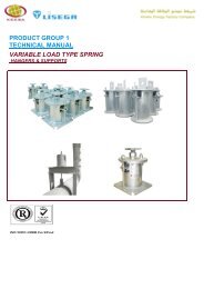
Spring 20 articulated spring support<br />
hangers 21 spring hanger<br />
22 heavy duty spring hanger<br />
25 spring hanger, seated<br />
26 heavy d. spr. hang., seated<br />
27 sway brace<br />
28 heavy duty spring support<br />
29 variable spring support<br />
72 base plate<br />
79 spring hanger trapeze<br />
Dynamically 30 shock absorber<br />
loaded 31 large bore shock absorber<br />
components 32 energy absorber<br />
33 installation extension<br />
35 weld-on bracket<br />
36-37 dynamic pipe clamp<br />
39 rigid strut<br />
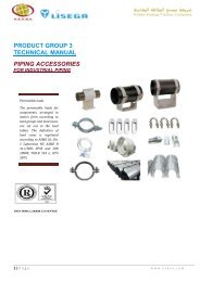
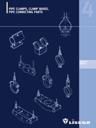
Pipe<br />
40 U-bolt<br />
surrounding 41 weld-on lug<br />
components 42-44 horizontal clamp<br />
45-48 riser clamp<br />
49 clamp base, lift-off restraints<br />
Pipe<br />
51 cylinder roller bearing<br />
bearings 52 double taper roller bearing<br />
and saddle 53 double cylinder roller bear.<br />
components 54 weld-on pipe saddle<br />
54 pipe saddle w. pipe clamp<br />
54 support tray<br />
55 lift-off restraint<br />
56 insulated pipe bearing<br />
57 weld-on pipe shoe<br />
58 stanchion<br />
58 elbow pad<br />
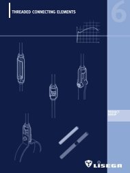
Threaded 60 eye nut<br />
connecting 61 clevis<br />
elements 62 turnbuckle<br />
63 hexagon nut<br />
64 rod coupling<br />
65 tie rod L/R<br />
66 tie rod<br />
67 threaded rod / stud bolt<br />
Structural 73 weld-on clevis<br />
attachment 74 weld-on pl. w. spher. wash.<br />
elements 75 weld-on eye nut<br />
76 beam adapter<br />
77 connecting plate<br />
78 beam clamp<br />
79 trapeze<br />
Load<br />
group<br />
C<br />
D<br />
1<br />
2<br />
3<br />
4<br />
5<br />
6<br />
7<br />
8<br />
9<br />
10<br />
20<br />
30<br />
40<br />
50<br />
Statically defined components<br />
Product group 1, 2, 4, 6, 7<br />
Nominal<br />
load [lbs]<br />
70<br />
141<br />
281<br />
562<br />
1125<br />
2250<br />
4495<br />
8990<br />
13490<br />
17985<br />
22480<br />
35970<br />
44960<br />
53955<br />
67400<br />
90000<br />
Ø Connection<br />
thread<br />
3/ 8<br />
3/ 8<br />
1/ 2<br />
1/ 2<br />
5/ 8<br />
3/ 4<br />
1<br />
11/ 4<br />
11/ 2<br />
13/ 4<br />
2<br />
21/ 4<br />
21/ 2<br />
23/ 4<br />
3<br />
31/ 4<br />
Wrench<br />
size<br />
11/ 16<br />
11/ 16<br />
7/ 8<br />
7/ 8<br />
11/ 16<br />
11/ 4<br />
15/ 8<br />
2<br />
23/ 8<br />
23/ 4<br />
31/ 8<br />
31/ 2<br />
37/ 8<br />
41/ 4<br />
45/ 8<br />
5<br />
3.5.1 Static components<br />
The nominal load is used for the determination<br />
of load groups. For the statically determined<br />
components in Product Groups 1, 2,<br />
4, 6, 7, the nominal load corresponds to<br />
the max. adjustment load of the spring elements,<br />
such as spring hangers and constant<br />
hangers. The maximum permissible hot load<br />
(load case H) lies considerably higher than<br />
the nominal load when components are<br />
used as rigid supports, and is tied to the<br />
load capacity of the connection threads.<br />
<strong>LISEGA</strong> threaded rods should therefore only<br />
be replaced in kind (see page 6.5, 6.6).<br />
Spring and constant hangers in the blocked<br />
position also count as rigid supports, whereby<br />
for cold loads in hydrostatic tests (short<br />
duration) the emergency loads (level C) can<br />
be exploited.<br />
For Product Group 4 (pipe connections) a limited<br />
area of overlapping in the load groups<br />
is foreseen, due to the temperature-related,<br />
variable spectrum of loading capacities. Data<br />
on the permissible loads relating to the respective<br />
operating temperature are set out for<br />
pipe connection components in the individual<br />
type data sheets.<br />
For Product Group 5 see 3.5.5, page 0.5.<br />
Ø<br />
Pin<br />
3/ 8<br />
3/ 8<br />
1/ 2<br />
1/ 2<br />
5/ 8<br />
13/ 16<br />
1<br />
15/ 16<br />
19/ 16<br />
13/ 4<br />
2<br />
23/ 8<br />
23/ 4<br />
23/ 4<br />
31/ 8<br />
31/ 2<br />
0<br />
Dyn. defined components<br />
Product group 3<br />
Load<br />
group<br />
–<br />
–<br />
1<br />
2<br />
3<br />
4<br />
5<br />
6<br />
7<br />
8<br />
9<br />
10<br />
20<br />
30<br />
40<br />
50<br />
Nominal<br />
load [lbs]<br />
–<br />
–<br />
675<br />
900<br />
1800<br />
4000<br />
10350<br />
22450<br />
44900<br />
78600<br />
123500<br />
224000<br />
448000<br />
670000<br />
900000<br />
1124000<br />
Ø<br />
Pin<br />
–<br />
–<br />
0.39<br />
0.39<br />
0.47<br />
0.59<br />
0.78<br />
1.18<br />
1.96<br />
2.36<br />
2.75<br />
3.93<br />
4.72<br />
5.51<br />
6.29<br />
7.08<br />
3.5.2 Dynamic components<br />
For dynamically determined<br />
units, the stipulation of the<br />
nominal loads follows from<br />
the meaningful division of<br />
the standardizable load<br />
spectrum. Here, the nominal<br />
load corresponds at the<br />
same time to the operating<br />
load for load event level<br />
A/B (ASME).<br />
As these components are<br />
generally used to guard<br />
against emergencies, the<br />
load event level C (ASME),<br />
possibly even level D, is<br />
usually adopted as the max.<br />
expected operating load.<br />
In each case the project<br />
engineer’s instructions<br />
apply.<br />
0.4