TECHNICAL SPECIFICATIONS - LISEGA
TECHNICAL SPECIFICATIONS - LISEGA
TECHNICAL SPECIFICATIONS - LISEGA

Create successful ePaper yourself
Turn your PDF publications into a flip-book with our unique Google optimized e-Paper software.
0.3<br />
are uniformly determined.<br />
For permissible stresses, a difference is made<br />
between statically and dynamically determined<br />
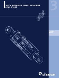
components. The units in product groups 1,<br />
2, 4, 5, 6 and 7 are stressed in only one<br />
load direction (statically or quasistatically)<br />
and are considered to be statically determined<br />
components. The components in Product<br />
Group 3, as well as their accessories, are<br />
loaded in alternating directions and are therefore<br />
regarded as dynamically determined<br />
components.<br />
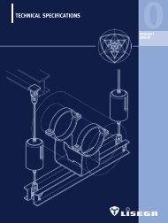
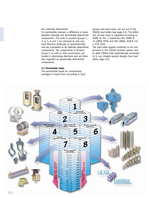
3.5 Permissible loads<br />
The permissible loads for components,<br />
arranged in matrix form according to load<br />
pipe surrounding<br />
components<br />
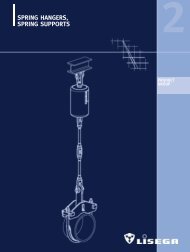
spring<br />
hangers<br />
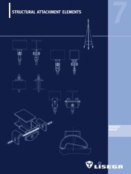
structural<br />
attachment elements<br />
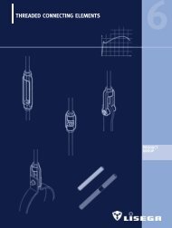
CONNECTING THREADS<br />
Ø CONNECTING BOLTS<br />
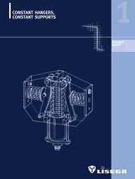
constant<br />
hangers<br />
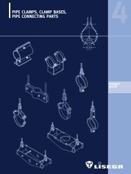
pipe bearing and<br />
saddle components<br />
load & connection<br />
compatibility<br />
dynamically<br />
loaded components<br />
design development<br />
tools<br />
LOAD GROUPS<br />
NOMINAL LOADS (lbs)<br />
threaded connecting<br />
components<br />
groups and load cases, are set out in the<br />
<strong>LISEGA</strong> load tables (see page 0.5). The definition<br />
of load cases is regulated according to<br />
ASME III, Div. 1 Subsection NF, ASME B<br />
31.1/MSS SP58 and DIN 18800, VGB-R 510<br />
L, KTA 3205.<br />
The load table applies uniformly to all components<br />
in the <strong>LISEGA</strong> modular system and<br />
to other <strong>LISEGA</strong> units systematically connected<br />
to it, e.g. integral special designs (see load<br />
table, page 0.5).