THE ROLE OF FABRICS IN TENSAIRITY - Eawag-Empa Library
THE ROLE OF FABRICS IN TENSAIRITY - Eawag-Empa Library
THE ROLE OF FABRICS IN TENSAIRITY - Eawag-Empa Library

You also want an ePaper? Increase the reach of your titles
YUMPU automatically turns print PDFs into web optimized ePapers that Google loves.
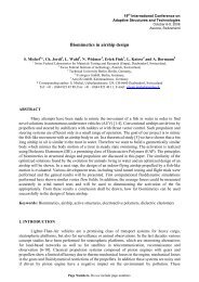
<strong>THE</strong> <strong>ROLE</strong> <strong>OF</strong> <strong>FABRICS</strong> <strong>IN</strong> <strong>TENSAIRITY</strong><br />
Rolf H. LUCHS<strong>IN</strong>GER and René CRETTOL<br />
<strong>Empa</strong>, Center for Synergetic Structures, CH-8600 Duebendorf, Switzerland<br />
E-mail: rolf.luchsinger@empa.ch rene.crettol@empa.ch<br />
ABSTRACT<br />
The new structural concept Tensairity ® is a synergetic combination of a pneumatic structure with a<br />
cable-strut structure. The beam or shell structures have interesting properties. They are very light,<br />
compact transport and storage is possible as well as fast and easy deployment. Furthermore, interesting<br />
lighting possibilities and forms can be realized with Tensairity. Thus, Tensairity is ideally suited for a<br />
variety of applications ranging from roof structures and foot bridges to temporary structures as<br />
advertisement pillars. Recent applications include a roof over a parking garage in Switzerland and a<br />
skier bridge in the French Alps. The basic models of Tensairity so far presented have treated the<br />
membrane as an inextensible hull. While this approximation is justified to understand the basic<br />
concepts of this new structure, the fabric properties do have an impact on the detailed behavior of<br />
Tensairity. Thus for a deeper understanding of Tensairity, the role of fabrics in Tensairity has to be<br />
investigated. Here we present first experimental studies highlighting the fabric nature of Tensairity. An<br />
initial response in the load-deflection diagram similar to the behavior of fabrics under biaxial testing is<br />
found.<br />
1. <strong>IN</strong>TRODUCTION<br />
Pneumatic structures have attracted engineers and architects since several decades. The combination of<br />
a membrane and air has some very attractive features. The set up and dismantling of pneumatic<br />
structures is fast by simple inflation or deflation of the structure and the transport and storage volume<br />
of inflatable structures are minimal. Pneumatic structures have found their application in civil<br />
engineering as airhouses. Inflatable emergency tents make use of the deployable nature. Despite of<br />
these remarkable properties one of the major drawbacks of pneumatic structures is the very limited load<br />
bearing capacity of airbeams. Substantial loads can only be carried with very high pressures in the<br />
airbeam. This leads to very high fabric tensions demanding for high strength and expensive fabrics.<br />
With increasing pressure airtightness of the hull becomes a serious issue and safety questions have to<br />
be addressed. Thus, high pressure airbeams can be used only in very special applications e.g. as<br />
military tents.<br />
The problem of the limited load bearing capacity of pneumatic structures is solved by the new<br />
structural concept Tensairity ® [1]. The basic Tensairity girder consists of an upper and a lower chord<br />
separated by an airbeam, where depending on the load situation one chord is purely under tension and<br />
can thus be a cable while the other chord has to withstand compressive forces and therefore acts like a<br />
strut. This combination of an airbeam and a cable-strut structure leads to a strong and very light beam<br />
element with compact transport and fast set up options as well as a low air pressure. Ideal applications<br />
of the patented technology are roof structures, footbridges and temporary structures as emergency<br />
1
idges and tents. In the roof for a parking garage in Montreux, Switzerland with 28 m span intensive<br />
use of the interesting lighting options of Tensairity was made (Fig. 1).<br />
Figure 1. Tensairity roof structure for a parking garage in Montreux, Switzerland with 28 m span, 2004<br />
(Luscher Architectes SA).<br />
Recently, a skier bridge in the French Alps with a span of 52 m was completed (Fig. 2). During the<br />
winter season, a ski slope runs over the bridge and thus the bridge deck is covered with a thick layer of<br />
snow leading to high loads. The bridge is an impressive demonstration of the potential of Tensairity for<br />
wide span structures with heavy loads.<br />
Figure 2. Tensairity skier bridge with 52 m span in the French Alps, 2005 (Charpente Concept SA,<br />
Barbeyer Architect & Airlight Ltd).<br />
2. SYNERGETIC STRUCTURES<br />
Tensairity is a combination of an airbeam and a cable-strut structure. This fusion of two so far<br />
separated technologies leads to a new structural element with improved properties. For example the<br />
load bearing capacity under bending load of a Tensairity girder is by factors higher than the sum of the<br />
load bearing capacity of the airbeam and the compression strut. The whole is greater than the sum of its<br />
parts. Tensairity is a synergetic combination of an airbeam and a cable-strut structure.<br />
2
To strengthen the research of Tensairity structures is the main focus of the recently founded Center for<br />
Synergetic Structures, a private public partnership between <strong>Empa</strong> and prospective concepts/Festo. For<br />
this purpose, new test facilities will be set up at <strong>Empa</strong> to study the behavior of Tensairity structures.<br />
These studies will help to deepen the understanding of Tensairity and to further optimize the<br />
technology and its applications. A special focus will be set on the mechanical characterization of the<br />
fabrics, as the fabric with its non-linear material behavior is a relevant part of Tensairity.<br />
Important properties of Tensairity are shown in Figure 2. Each property is related to the underlying<br />
airbeam or cable-strut structure, where it is inherited from. Little weight and small transport volume are<br />
properties of both the pneumatic structure and the cable-strut structure. The capacity to carry heavy<br />
loads goes back to the cable-strut structure, while fast set up, the temporary nature, thermal insulation,<br />
lighting options, adaptiveness and so on do have their roots in the pneumatic structure. The low air<br />
pressure is an emergent property of the combination of both structures and therefore shown with<br />
dashed arrows.<br />
pneumatic<br />
structure<br />
Tensairity ®<br />
Tensairity ®<br />
Tensairity ®<br />
- light weight<br />
- heavy loads<br />
-low pressure (~100 mbar)<br />
- small transport volume<br />
- fast setup<br />
-temporary<br />
- thermal insulation<br />
- transparency<br />
- lighting<br />
-floating<br />
- adaptable<br />
-safe<br />
Figure 2. Properties of Tensairity, a synergetic combination of a pneumatic structure with a cable-strut<br />
structure.<br />
An important issue is the safety of Tensairity. The vulnerability of the airbeam is an undesired property<br />
of Tensairity taken over by the pneumatic structure. An injury of the hull of a pneumatic structure leads<br />
to a loss of air and the resulting drop of the air pressure endangers the integrity of the structure. The<br />
situation is different in Tensairity due to an inherited property of the cable-strut structure. The struts or<br />
chords in Tensairity have a resulting bending stiffness. They can be designed such that the dead load of<br />
the structure is carried by the chords without the need of the stabilisation of the airbeam. The air<br />
pressure is needed for sustaining the additional live loads [2]. In a lightweight Tensairity structure as<br />
the roof over the parking garage in Montreux, the live load is roughly ten times higher than the dead<br />
load. Stabilization by the over pressure is crucial for the live load, but the integrity of the structure is<br />
not jeopardized with zero pressure solely under dead load. It also enables a pressure release in a<br />
Tensairity structure when e.g. people have to enter the airbeam for service reasons. In structures like<br />
the roof in Montreux high live load events are rare. The risk of a complete air loss in a Tensairity girder<br />
with a high live load at the same time is very small. Furthermore, all larger Tensairity structures are<br />
connected to an external fan, which starts blowing when the pressure drops below some threshold value.<br />
This fan can easily compensate undesired air loss caused e.g. by a gun shot of vandals. And the<br />
3<br />
cable-strut<br />
structure
integrity of Tensairity structures can be easily checked by a simple pressure sensor or even by the<br />
naked eye. The combination of an airbeam and a cable-strut structure enables new safety concepts for<br />
Tensairity far outreaching the safety of conventional pneumatic structures.<br />
3. BASIC <strong>TENSAIRITY</strong><br />
The basic principles of Tensairity have been described by Luchsinger et al. [3]. As a structural analogy,<br />
a Tensairity girder can be compared with a truss girder. Both structures have an upper and a lower<br />
chord. In Tensairity, however, the airbeam takes over the role of the vertical and diagonal struts of the<br />
truss [4]. The struts in the truss have essentially three functions: load transfer from the upper to the<br />
lower chord, reduction of the buckling length of the chord under compression and transfer of shear<br />
forces by the diagonal struts. In Tensairity, the load transfer from the upper to the lower chord is<br />
accomplished by the pretensioned fabric of the airbeam. Note, that a compressive force is transmitted<br />
by a fabric. The buckling length of the chord under compression is reduced due to the stabilization by<br />
the airbeam in Tensairity. The chord can be viewed as a beam on an elastic foundation. The buckling<br />
length is then a function of the bending stiffness of the chord and the spring constant of the foundation,<br />
which in the case of Tensairity is determined by the over pressure [5]. A proper choice of the bending<br />
stiffness and the over pressure can lead to a buckling load which is higher than the yield load of the<br />
chord, a property we call buckling free compression. Thus, load transfer from the upper to the lower<br />
chord and reduction of the buckling length can be well taken over by the airbeam. The transfer of shear<br />
forces in Tensairity is less obvious and subject of further studies.<br />
In the basic Tensairity model the fabric is treated as an inextensible hull. The non-linear and<br />
non-isotropic fabric behavior is not taken into consideration in these models. This approximation is<br />
justified to understand the basic concepts of Tensairity. However, the fabric properties do certainly<br />
influence the behavior of Tensairity structures. Understanding the fabric specific behavior of Tensairity<br />
is important to gain deeper insight into the potential of this new structure. With increasing size of the<br />
applications of Tensairity, where testing of a 1:1 prototype is not feasible and a reliable numerical<br />
analysis is crucial, a detailed physical model including the fabric specific properties based on<br />
experimental and theoretical studies is needed (Fig. 3).<br />
Figure 3. The experimental set up for the study of the behavior of Tensairity beams.<br />
4
3. FABRIC EFFECTS <strong>IN</strong> <strong>TENSAIRITY</strong><br />
Tensairity beams have essentially the shape of a cylinder or a spindle [6]. The fabric is stressed both in<br />
the hoop and longitudinal direction due to the internal over pressure. The ratio of the hoop stress and<br />
the longitudinal stress in a cylinder is 2:1. For slender spindles, approximately the same ratio is found.<br />
The magnitude of the stress is determined by the over pressure and the radius of the cylinder. Since the<br />
fabric in Tensairity is in a biaxial stressed state, biaxial tests are important to investigate the fabric<br />
properties for Tensairity. In Figure 4 left, the force-strain response in the warp direction is shown for a<br />
biaxial test of a polyamide based fabric [7]. A force controlled load profile with a ratio of 2:1 in warp<br />
and weft direction is applied for five load cycles. The total applied force varies between 1.25 kN and<br />
7.5 kN in the warp direction and half of that value in the weft direction. The fabric shows an initial<br />
response in the first cycle and gradually converges in further cycles.<br />
The load-displacement response of a Tensairity beam under bending load is shown in Fig. 4 right. A<br />
spindle shaped Tensairity girder with 5 m length and a central diameter of 0.5 m is used for this<br />
experimental investigations in the laboratory (Fig. 3). The fabric of the Tensairity girder is identical to<br />
the fabric of the biaxial test. Since this fabric is not airtight, a thin PU foil is embedded. An over<br />
pressure of 150 mbar is applied for this test. The upper and lower chords of the Tensairity test beam are<br />
made of aluminum. In the experiment, a central bending load is applied by means of a hydraulic piston<br />
in three load cycles ranging from 0 kN to 0.9 kN. The fabric adapts to the new load condition during<br />
the first load cycle. The load-displacement responses of the second and third load cycle are almost<br />
identical. The Tensairity girder also shows a pronounced hysteresis indicating energy dissipation. This<br />
hysteresis has to be attributed to the air beam, since the aluminum chords of the Tensairity girder have<br />
an elastic behavior. It can result from the fabric or from energy dissipation into the compressed air. The<br />
details behind the hysteresis are not yet understood and are subject of further studies. It is in any case<br />
an interesting aspect regarding the dynamic properties and damping behavior of Tensairity girders.<br />
force [kN]<br />
8<br />
6<br />
4<br />
2<br />
Biaxial fabric test<br />
0<br />
0 1 2 3<br />
strain [%]<br />
4 5 6<br />
load [kN]<br />
Figure 4. Experimental data of a biaxial fabric test (left) and a Tensairity beam under central bending<br />
load (right).<br />
5<br />
1.2<br />
1<br />
0.8<br />
0.6<br />
0.4<br />
0.2<br />
0<br />
Tensairity beam p = 150 under mbar bending load<br />
-0.2<br />
0 10 20 30 40 50<br />
displacement [mm]
4. CONCLUSIONS<br />
Tensairity is a synergetic combination of an airbeam and a cable-strut structure or, in other words, of<br />
fabrics, compressed air, cables and struts. The fabric plays an important role in Tensairity. It is<br />
pretensioned due to the compressed air. Therefore it can transfer compressive forces from the upper<br />
chord to the lower chord. The fabric stabilizes the chord under compression against buckling. And the<br />
fabric has to take care of shear forces. The fabric is the key to the outstanding properties of Tensairity<br />
such as light weight, fast and simple setup, compact transport and storage volume, interesting lighting<br />
options, adaptiveness and so on. The fabric has a complex non-linear material behavior. Part of this<br />
behavior is transmitted to the Tensairity structure, as can be seen by the initial response to a new load<br />
condition of the fabric under biaxial testing and the Tensairity beam under bending load. Thus a deeper<br />
understanding of Tensairity is strongly connected to a detailed analysis of the material properties of the<br />
involved fabrics. Research along these lines is underway. As a matter of fact, the fabric is more than the<br />
compartment of the compressed air. It is an important part of the interesting and rich behavior of<br />
Tensairity structures.<br />
REFERENCES<br />
[1] Tensairity ® is a technology of the Swiss company Airlight Ltd developed in close collaboration with<br />
prospective concepts ag. The research activities of prospective concepts have been recently transferred<br />
to the Center for Synergetic Structures at <strong>Empa</strong>, the Swiss Federal Laboratories for Materials Testing<br />
and Research. For further information about Tensairity see www.airlight.biz .<br />
[2] R.H. Luchsinger, R. Crettol (2006), “Adaptable Tensairity”, F. Scheublin, A. Pronk, A. Borgard and<br />
R. Houtman (eds.), Adaptables’06, Proceedings of the joint CIB, Tensinet and AISS international<br />
conference on adaptability in design and construction, Eindhoven.<br />
[3] R.H. Luchsinger, A. Pedretti, P. Steingruber, M. Pedretti (2004), “The new structural concept<br />
Tensairity: Basic Principles”, A. Zingoni (ed.), Progress in Structural Engineering, Mechanics and<br />
Computation, A.A. Balkema Publishers, London.<br />
[4] R.H. Luchsinger, R. Crettol, P. Steingruber, A. Pedretti, M. Pedretti (2005), “Going strong: from<br />
inflatable structures to Tensairity”, E. Onate and B. Kröplin (eds.), Textile composites and inflatable<br />
structures II, CIMNE, Barcelona.<br />
[5] R.H. Luchsinger, A. Pedretti, P. Steingruber, M. Pedretti (2004), “Light weight structures with<br />
Tensairity”, R. Motro (ed.), Shell and Spatial Structures from Models to Realizations, Editions de<br />
l’Espérou, Montpellier.<br />
[6] A. Pedretti, P. Steingruber, M. Pedretti, R.H. Luchsinger (2004), “The new structural concept<br />
Tensairity: FE-modeling and applications“, A. Zingoni (ed.), Progress in Engineering, Mechanics and<br />
Computation, A.A. Balkema Publishers, London.<br />
[7] Biaxial tests were made by the Laboratorium Blum, Stuttgart, Germany.<br />
6