THE ROLE OF FABRICS IN TENSAIRITY - Eawag-Empa Library
THE ROLE OF FABRICS IN TENSAIRITY - Eawag-Empa Library
THE ROLE OF FABRICS IN TENSAIRITY - Eawag-Empa Library

Create successful ePaper yourself
Turn your PDF publications into a flip-book with our unique Google optimized e-Paper software.
3. FABRIC EFFECTS <strong>IN</strong> <strong>TENSAIRITY</strong><br />
Tensairity beams have essentially the shape of a cylinder or a spindle [6]. The fabric is stressed both in<br />
the hoop and longitudinal direction due to the internal over pressure. The ratio of the hoop stress and<br />
the longitudinal stress in a cylinder is 2:1. For slender spindles, approximately the same ratio is found.<br />
The magnitude of the stress is determined by the over pressure and the radius of the cylinder. Since the<br />
fabric in Tensairity is in a biaxial stressed state, biaxial tests are important to investigate the fabric<br />
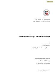
properties for Tensairity. In Figure 4 left, the force-strain response in the warp direction is shown for a<br />
biaxial test of a polyamide based fabric [7]. A force controlled load profile with a ratio of 2:1 in warp<br />
and weft direction is applied for five load cycles. The total applied force varies between 1.25 kN and<br />
7.5 kN in the warp direction and half of that value in the weft direction. The fabric shows an initial<br />
response in the first cycle and gradually converges in further cycles.<br />
The load-displacement response of a Tensairity beam under bending load is shown in Fig. 4 right. A<br />
spindle shaped Tensairity girder with 5 m length and a central diameter of 0.5 m is used for this<br />
experimental investigations in the laboratory (Fig. 3). The fabric of the Tensairity girder is identical to<br />
the fabric of the biaxial test. Since this fabric is not airtight, a thin PU foil is embedded. An over<br />
pressure of 150 mbar is applied for this test. The upper and lower chords of the Tensairity test beam are<br />
made of aluminum. In the experiment, a central bending load is applied by means of a hydraulic piston<br />
in three load cycles ranging from 0 kN to 0.9 kN. The fabric adapts to the new load condition during<br />
the first load cycle. The load-displacement responses of the second and third load cycle are almost<br />
identical. The Tensairity girder also shows a pronounced hysteresis indicating energy dissipation. This<br />
hysteresis has to be attributed to the air beam, since the aluminum chords of the Tensairity girder have<br />
an elastic behavior. It can result from the fabric or from energy dissipation into the compressed air. The<br />
details behind the hysteresis are not yet understood and are subject of further studies. It is in any case<br />
an interesting aspect regarding the dynamic properties and damping behavior of Tensairity girders.<br />
force [kN]<br />
8<br />
6<br />
4<br />
2<br />
Biaxial fabric test<br />
0<br />
0 1 2 3<br />
strain [%]<br />
4 5 6<br />
load [kN]<br />
Figure 4. Experimental data of a biaxial fabric test (left) and a Tensairity beam under central bending<br />
load (right).<br />
5<br />
1.2<br />
1<br />
0.8<br />
0.6<br />
0.4<br />
0.2<br />
0<br />
Tensairity beam p = 150 under mbar bending load<br />
-0.2<br />
0 10 20 30 40 50<br />
displacement [mm]