J. Borkowski, K. Smith, D. Hagrman, and J. Rhodes, III
J. Borkowski, K. Smith, D. Hagrman, and J. Rhodes, III
J. Borkowski, K. Smith, D. Hagrman, and J. Rhodes, III

Create successful ePaper yourself
Turn your PDF publications into a flip-book with our unique Google optimized e-Paper software.
INTEGRATION OF AN ENGINEERING-GRADE,<br />
RELOAD SPECIFIC CORE MODEL INTO<br />
A REAL-TIME TRAINING SIMULATOR<br />
Jeffrey <strong>Borkowski</strong>, Kord <strong>Smith</strong><br />
Daniel <strong>Hagrman</strong>, Joel <strong>Rhodes</strong>, <strong>III</strong><br />
Studsvik Sc<strong>and</strong>power<br />
504 Shoup Avenue, Suite 201<br />
Idaho Falls, ID 83402<br />
jeff @soa.com<br />
1. INTRODUCTION<br />
This paper describes the integration of SIMULATE-3R (S3R) into the Oconee Nuclear Station<br />
Simulator’s Windows Integrated Simulator Environment (WISE). The primary purpose of this<br />
effort was to enable reload-specific simulation by direct usage of nuclear core design data. The<br />
sections that follow explain the relationship of the simulator core model to the core design<br />
models, the integration with existing simulator components, <strong>and</strong> the usage of the integrated<br />
WISE at both the Oconee Simulator <strong>and</strong> at SSP.<br />
2. OBJECTIVES<br />
The integration procedure was shaped primarily by the objectives of the ONSS staff, the Duke<br />
Power Core Physics Group, <strong>and</strong> Studsvik Sc<strong>and</strong>power. All groups had the overriding objective of<br />
cycle specific simulator performance, but with some differences in focus.<br />
• The focus of the core physics group was to facilitate direct usage of core design data in the<br />
simulator without any ad hoc collapsing <strong>and</strong>/or tuning <strong>and</strong> the associated time burden of that<br />
sort of data manipulation.
• One focus of the ONSS staff was to perturb the usage environment of the current simulator as<br />
little as possible, allowing the training staff to maintain as much as possible of their current<br />
patterns, techniques, <strong>and</strong> approaches to scenario generation. A second major objective was to<br />
integrate S3R into their structured development environment, preserving consistent <strong>and</strong><br />
longterm software configuration control.<br />
• The Studsvik Sc<strong>and</strong>power (SSP) focus was primarily to satisfy the above customer objectives<br />
but simultaneously preserve the general structure of the software such that it remained<br />
consistent with the core design codes from which it originated.<br />
3. PURPOSE FOR DEVELOPMENT OF S3R<br />
3.1 STATUS OF PREVIOUS GENERATION MODELS<br />
Many real time core models of the previous generation tended to use relatively simple core<br />
models as a result of hardware limitations at the time of their development. Several of the<br />
simplifying assumptions include:<br />
• transient simulation is performed in the axial direction only,<br />
• azimuthal effects are treated synthetically via externally determined tilting functions, <strong>and</strong><br />
• thermal hydraulic feedback is treated through the lumping of coolant channels into<br />
representative sub-regions in the core.<br />
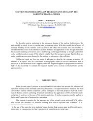
The level of detail is constrasted in Figure1<br />
Figure 1. Contrast in level of detail between a typical simulator core model<br />
<strong>and</strong> a nodal, three-dimensional transient analysis model.<br />
An additional limitation of these core models is their ability to represent accurately the core as<br />
designed. One reason is the numerical models in the simulator are not as advanced as those in the<br />
core design tools. Another reason is that the basic nuclear data used in generic simulator core
models does not accurately represent the behavior of modern lattice designs <strong>and</strong> reload strategies.<br />
As a result the static <strong>and</strong> dynamic characteristics of the training simulator may not represent<br />
those of the actual core. One possible approach to this problem is for the core physics group to<br />
make parametric adjustments to the nuclear data <strong>and</strong> external functions in the simulator, such<br />
that the simulator core is tuned to the core design. The limitations of this approach are:<br />
• the tuning process must be performed every cycle,<br />
• the process is labor intensive, <strong>and</strong><br />
• the result typically can be validated only with steady-state calculations.<br />
An altenative method is presented here, which describes the extension of familiar core design<br />
codes <strong>and</strong> processes to a real-time transient core model. Such a model is inherently cycle specific<br />
<strong>and</strong> demonstrates high fidelty to the core design. Further, this approach uses no external data<br />
manipulation, collapsing, or other such tuning.<br />
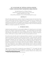
3.2 BASIC NUCLEAR DATA<br />
The reload-specific data is generated by the core physics group as part of the familiar core design<br />
process (Figure 2). Basic two-group nuclear data is generated with the lattice physics code<br />
CASMO-4 1 (or its predecessor, CASMO-3). This data is stored in a binary library for use in<br />
SIMULATE-3. SIMULATE-3 uses an advanced nodal method (QPANDA 2 ) to solve the threedimensional<br />
neutron diffusion equation. In addition to loading <strong>and</strong> depleting the core model,<br />
SIMULATE-3 reconstructs local pin powers <strong>and</strong> detector responses. Every assembly <strong>and</strong> all<br />
reflectors are modeled explicitly.<br />
Figure 2. Schematic of In-Cycle Data Generation
5. OCONEE’S SIMULATOR ENVIRONMENTS (WISE <strong>and</strong> VISE)<br />
5.1 OVERVIEW OF THE ENVIRONMENT<br />
The Oconee Simulator runs native on a single DELL dual CPU machine running Windows NT.<br />
The software is designed to take advantage of the WIN32 API which incorporates a multiprocess/multi-threaded<br />
design with a common shared memory architecture. This architecture<br />
allows the simulator code to be designed into small segments <strong>and</strong> processes based on common<br />
functionality. This significantly facilitates the design <strong>and</strong> debugging process as will be shown<br />
shortly. Presently the simulator has two environments:<br />
• WISE (Windows Integrated Simulator Environment)<br />
Production/Training Environment<br />
Runs on the Production computers <strong>and</strong> is the Simulator Design Database<br />
software.<br />
• VISE (Virtual Integrated Simulator Environment)<br />
Simulator Developer Environment<br />
Executes on the simulator developers personel development environment<br />
workstation <strong>and</strong> is maintained solely by the developer. This code is a superset of<br />
the WISE software code base <strong>and</strong> is considered volitile.<br />
5.2 DEVELOPMENT ENVIRONMENT (VISE)<br />
Visual Studio TM 6.0 is the development environment used for design <strong>and</strong> debug of simulator<br />
software. The Oconee Simulator software is comprised of several different languages including<br />
C, C++, Visual Basic, <strong>and</strong> Digital FORTRAN. The language chosen for a particular task is<br />
dependent on the intended function. The language implementations are shown below:<br />
• Executives - C <strong>and</strong> C++<br />
• Modeling – FORTRAN<br />
• Network communications – C <strong>and</strong> C++<br />
• Instructor Station – Visual Basic <strong>and</strong> C<br />
• Support Utilities – Visual Basic<br />
The table below list the language with the associated activity:<br />
• FORTRAN – All thermodynamic modeling <strong>and</strong> legacy simulator software<br />
• C <strong>and</strong> C++ - All process executives <strong>and</strong> network interface software
• Visual basic – Instructor Station, Offline support<br />
utility processes, <strong>and</strong> all database access software<br />
Visual Studio TM makes it possible to seamlessly integrate<br />
FORTRAN, C, <strong>and</strong> C++ software. This tight integration<br />
facilitates choosing a language for a particular function (one<br />
process may incorporate several different software<br />
languages) based on the inherent qualities of that language.<br />
With the proper Visual Studio TM project design, the<br />
software developer can easily intermix C, C++, <strong>and</strong><br />
FORTRAN in the same process.<br />
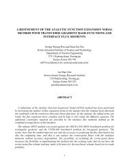
5.3 DESIGN VERSUS RUNTIME<br />
The design <strong>and</strong> runtime environments are equivalent (code<br />
is not optimized for WISE execution) on the simulator <strong>and</strong><br />
this facilitates full source code debugging within the<br />
runtime environment, regardless of language selection. The<br />
Oconee simulator source code in the Visual Studio TM is<br />
WYSIWYG. The Visual Studio TM project includes all<br />
source (each source module is explicitly process activity. In<br />
other words, st<strong>and</strong>ard practice is to execute the simulator<br />
from within the Visual Studio TM when developing code.<br />
The developer seldom leaves the Visual Studio TM<br />
environment when designing <strong>and</strong> debugging simulator code.<br />
This is invaluable for tracking hard to find anamolies <strong>and</strong><br />
bugs which may occure during training sessions or for<br />
tracing program execution to ensure correct program<br />
execution. With the production <strong>and</strong> debugging<br />
environments being the same, this makes it much easier to<br />
reproduce simulator anomolies (all any aborts or math<br />
errors report the actual address that can be viewed in the<br />
Visual Studio TM ). At Oconee, each simulator software<br />
developer has at his desk the complete simulator source<br />
code, runtime database, simulator initial condition file sets,<br />
<strong>and</strong> Windowed Instructor Station (WIS). This allows each<br />
developer to work in a Virtual simulator environment<br />
which is totally isolated from the production environment.<br />
When in VISE mode, the simulator initializes all I/O data<br />
structures so that it appears that I/O is available. Note that<br />
Figure 3. Typical Visual<br />
Studio Project view.<br />
when in this mode, all other simulator processes that h<strong>and</strong>le external interfaces are not executing<br />
<strong>and</strong> only the model dynamics are running. This significantly minimizes the amount of dead code<br />
that must be carried with the simulation. When the software developer determines that the code is<br />
ready for test, the software developer will attach the WISE computer to the developers VISE<br />
workstation (via network share) <strong>and</strong> execute the test process on the WISE computer (the VISE<br />
environment switches to a WISE environment), thus allowing complete testing of the developers
software without ever making a single change on the WISE computer. This design has significant<br />
benefits compared to the old primary/secondary development system approach (Note: each<br />
software developer has a separate <strong>and</strong> independent VISE workstation at his desk). Once the<br />
developers software is deemed ready for production (fully tested <strong>and</strong> validated), the developer<br />
will integrate the appropriate software modules (subroutines) into the simulator design database.<br />
This code will then be compiled into the WISE production process <strong>and</strong> distributed to all WISE<br />
computers.<br />
The VISE design was utilized by SSP in this project. SSP received a copy of the Oconee VISE<br />
model thus allowing the developers at SSP access to all of the same development tools <strong>and</strong><br />
environments that are available at Oconee. SSP developers could then work with the full<br />
simulator load just as if they were at Oconee. This has proven to be very successful <strong>and</strong> very<br />
efficient.<br />
5.4 NT PROCESS SEGMENTATION<br />
As shown earlier, WISE is comprised of five different processes. The list below describes this<br />
segmented functionality <strong>and</strong> software languages used:<br />
• Simulator Executive <strong>and</strong> Dynamic modeling (S3R model)<br />
• Language: C, C++, FORTRAN<br />
• I/O Executive<br />
• Language: C<br />
• Plant Compuer Executive<br />
• Language: C, FORTRAN<br />
• Radiation Display<br />
• Language: C, FORTRAN<br />
• XRVLIS Display<br />
• Language: C, FORTRAN<br />
This segmented design functionality yields great benefits from the software developers<br />
perspective. The developer has no need to carry the additional functionality of external interfaces<br />
during the design <strong>and</strong> debug phase. Generally, the software developer will only execute the<br />
simulator dynamics executive during this phase of development <strong>and</strong> the VISE environment is<br />
totally isolated from any other simulator modification activities. This gives the developer<br />
significant freedom in designing code as the development <strong>and</strong> test environments are completed in<br />
total isolation. Only after the change has been fully validated will it be incorporated into the<br />
simulator design database.
6.1 S3R AS A PROCESS MODULE<br />
6. S3R INTEGRATION INTO WISE<br />
The S3R model was added to the WISE Visual Studio TM project as a WIN32 static library<br />
project. All S3R source code modules reside in this project group. Additionally, a global<br />
“Preprocessor Variable” was defined which allowed for a single source base to be maintained<br />
thoughout the project (Old core model exist along side S3R). Even though the S3R source was<br />
included in the project, its inclusion into the linked process could be turned on <strong>and</strong> off by the<br />
“Preprocessor Variable”, <strong>and</strong> during the compile process the source code would automatically<br />
configure itself for proper execution. The interface to S3R is through a single subroutine call<br />
with two passed arrayed parameters. One array is an input array <strong>and</strong> the other array is an output<br />
array. A small amount of wrapper code was added to pack <strong>and</strong> unpack the input <strong>and</strong> output<br />
arrayed data.<br />
6.2 TRANSIENT AND REAL-TIME PERFORMANCE<br />
S3R is a specialized version of SIMULATE-3K 3 . SIMULATE-3K is the transient analog of<br />
SIMULATE-3, also using the QPANDA nodal model. Thermal-hydraulic conditions are modeled<br />
using a five-equation Drift Flux fluid model coupled to a pin conduction model 4 .<br />
All reload core data comes from SIMULATE-3 restart files which are generated at multiple<br />
points in the cycle depletion. SIMULATE-3K reads the core follow nuclear data library directly.<br />
Real-time performance in the S3R implementation is achieved via parallel <strong>and</strong> serial<br />
accelerations of SIMULATE-3K. Parallel acceleration is achieved using threads. The major<br />
threaded modules are:<br />
• the tabular cross-section evaluation,<br />
• the thermal-hydraulic channel sweep,<br />
• the neutronic flux iteration,<br />
• the delayed neutron precursor integration, <strong>and</strong><br />
• the fission source evaluation.<br />
These modules account for 80 per cent of the required CPU execution time. The speed-up factor<br />
achieved via threading depends on the hardware. On average, 75 percent theoretical speedup is<br />
seen when taken across all threaded components.<br />
Serial acceleration is achieved by modifications to time-step, nodalization, <strong>and</strong> nuclear data<br />
evaluation. In all cases, S3R solves its field equations for every assembly radially <strong>and</strong> typically<br />
uses the following run time configuration:<br />
• 0.25 s time step,<br />
• 12 axial, 1 radial node per assembly,
• Two-dimensional cross-section table lookup, <strong>and</strong>,<br />
• Periodic recalculation of the nuclear coupling coefficients matrices, typically once per second.<br />
No physical models differ between S3R <strong>and</strong> SIMULATE-3K, so as these restrictions are relaxed,<br />
the SIMULATE-3K solution is obtained. It should be noted that because the physical models of<br />
SIMULATE-3K <strong>and</strong> SIMULATE-3R are identical, SIMULATE-3K can be used in a slower than<br />
real-time mode to assess the performance of the real-time mode.<br />
Real time performance for the ONSS was obtained using a 2 CPU Pentium II 400 MHz machine<br />
with approximately 50 per cent spare margin. Additional details on the acceleration techniques<br />
used in S3R, as well as timing studies, have been published by <strong>Rhodes</strong> et al 5 .<br />
Table 1: Configuration Differences Between S3K <strong>and</strong> S3R<br />
S3R<br />
12 Axial Mesh 24/25 Axial Mesh<br />
PWR: 1 radial nodes/asm PWR: 4 radial node/asm<br />
BWR: 1 radial node /asm BWR: 1 radial node /asm<br />
0.2 - 0.25 sec time step Variable <strong>and</strong> Automatic<br />
Period Coupling Coefficent Updates Countinuous Coupling Coefficient Updates<br />
Fixed Fluxed Iterations Variable Flux Iterations<br />
No Implicitness Iteration Full Implicitness Iterations<br />
Full Pin Power Reconstruction Synthetic Pin Power Reconstruction<br />
6.3 CYCLE SPECIFIC DATA<br />
From a core physics point of view, the primary advantage of the S3R core model is it uses the<br />
exact same data that the core physics group uses, <strong>and</strong> uses that data in the same format. The core<br />
physics group designs, depletes, <strong>and</strong> analyzes the reload using the SSP products CASMO-4 <strong>and</strong><br />
SIMULATE-3. In this process, two fundamental binary data sets are generated <strong>and</strong> used:<br />
• A basic nuclear data library which represents the fuel characteristics functionalized against<br />
burnup <strong>and</strong> feedback variables.<br />
S3K
• One or more restart files. These files are generated during depletion analysis <strong>and</strong> capture the<br />
instantaneous core state at a particular burnup.<br />
These data sets provide all the necessary data for S3R initialization. Further, the numerical<br />
methods employed in S3R are the same as in the core design codes, so the fidelty of the S3R<br />
physical methods to the offline codes is extremely high. In practice, the core design group<br />
actually generates many more restart files than is practical for simulator usage. A pratical subset<br />
was established as several Effective Full Power Day (EFPD) statepoints:<br />
• 0 EFPD, for Zero Power Physics Testing <strong>and</strong> startup<br />
• 5 EFPD, for BOL training<br />
• 250 EFPD, for MOL training<br />
• 440 EPFD, for EOL training<br />
In this procedure, the effort burden on the core physics group is basically file transfer to the<br />
ONSS staff.<br />
7.1 PRIMARY CONSTRUCTS<br />
7. INTEGRATION STRUCTURE<br />
The ONSS development environment is based on two primary constructs:<br />
• a modular source code configuration which is fully integrated into the Microsoft Visual<br />
Studio TM development system; <strong>and</strong><br />
• a shared memory global database, which h<strong>and</strong>les variable registration <strong>and</strong> passes information<br />
among the modules <strong>and</strong> to the simulator display.<br />
The Visual Studio TM project is organized into a hierachy of several subprojects. These<br />
subprojects have been created along the lines of physical function, or in some cases to<br />
differentiate among source code from multiple vendor.<br />
7.2 ONSS SIMULATOR COUPLING<br />
The S3R core model is coupled to the pre-existing reactor coolant system (RCS) <strong>and</strong> control<br />
system. Thermal-hydraulic boundary conditions <strong>and</strong> rod positions are obtained from these<br />
models. S3R returns thermal power, excore detector response, incore detector response, <strong>and</strong><br />
thermocouple temperatures to the RCS <strong>and</strong> control system.<br />
This coupling is implemented via the ONSS Windows Instructor Station (WIS) developed by the<br />
Oconee Simulator Support Group. The WIS acts as both an executive <strong>and</strong> developmental system<br />
for the simulator as a whole. The WIS is fully integrated in the MS Visual Studio TM environment.<br />
As such, each individual physical model is a unique project in this environment, addressing both<br />
local memory <strong>and</strong> a partition of shared (or “global”) memory. The contents of global memory are
typically those data segments that are required for panel display, snapshots, or for coupling to<br />
another model.<br />
7.3 USAGE AND VERIFICATION<br />
Because the SIMULATE-3 restart files are accessed directly, the simulator may be initialized at<br />
any cycle exposure. Typical base starting exposures are 0 EFPD for physics testing <strong>and</strong><br />
approximately 5, 250, <strong>and</strong> 450 EFPD for in-cycle training, as stated above. Instantaneous<br />
conditions of the core model may be saved via the intrinsic snapshot capability of the WIS.<br />
Many off-nominal transients do not have a measured assessment capability. However, it is<br />
possible to assess the performance of the S3R model against zero power physics tests (ZPPT) for<br />
a known cycle. When assessed against Oconee 1 Cycle 18, the S3R based model matched the<br />
measured critical rod position at reference boron to within 1%.<br />
CONCLUSION<br />
The inclusion of the S3R core model in the ONSS has facilitated the direct usage of reload-<br />
specific core design data in a simulator training. The procedures required for this effort are<br />
greatly simplified because the simulator model accesses directly the core design calculational<br />
result. Additionally, the usage of modern programming tools in this development effort has<br />
facilitated rapid <strong>and</strong> robust development.<br />
REFERENCES<br />
1. M. EDENIUS, K. EKBERG, B. H. FORSSEN, D.G. KNOTT, “CASMO-4 A Fuel Assembly<br />
Burnup Program User’s Manual,” Studsvik/SOA-95/1, Studsvik, 1995.<br />
2. K. SMITH, D. VERPLANCK, M. EDENIUS, “QPANDA: An Advanced Nodal Method for<br />
LWR Analyses,” Trans. Am. Nuc. Soc., 50, 532 (1985).<br />
3. J. BORKOWSKI, J. RHODES <strong>III</strong>, P. ESSER, K. SMITH, “A Three-Dimensional<br />
Transient Analysis Capability for SIMULATE-3,” Trans. Am. Nuc. Soc., 71, 456 (1994).<br />
4. D. KROPACZEK, K. SMITH, J. BORKOWSKI, “A Fully Implicit Five Equation Channel<br />
Hydraulic Model for SIMULATE-3K,” Joint Intl. Conf. on Math. Methods <strong>and</strong><br />
Supercomputing for Nucl. Applications, 1421, (1997).<br />
5. J. RHODES <strong>III</strong>, K. SMITH, D. HAGRMAN, J. BORKOWSKI, “Real-Time Reactor<br />
Simulation with a Multi-Threaded Shared Memory Version of SIMULATE-3K,” Advances<br />
in Nuclear Fuel Management II, EPRI TR-107728-V2, 20-1 (1997).