K. Kobayashi and S. Tsumura
K. Kobayashi and S. Tsumura
K. Kobayashi and S. Tsumura

You also want an ePaper? Increase the reach of your titles
YUMPU automatically turns print PDFs into web optimized ePapers that Google loves.
AN ANALYSIS OF XENON OSCILLATIONS<br />
USING MULTI-POINT KINETICS EQUATIONS<br />
Keisuke <strong>Kobayashi</strong> ∗ <strong>and</strong> Shingo <strong>Tsumura</strong><br />
Department of Nuclear Engineering, Kyoto University<br />
Yoshida, Sakyoku, Kyoto, Japan<br />
kobayasi@ip.media.kyoto-u.ac.jp, tsumura@nucleng.kyoto-u.ac.jp<br />
ABSTRACT<br />
Using the multi-point kinetics equations derived by using the region-wise importance functions<br />
to produce fission neutrons, xenon oscillations of thermal reactors are analyzed, <strong>and</strong><br />
a method to terminate the xenon oscillation is investigated. An advantage of the present<br />
method is that this method can be applied to any geometries of multi-dimensions by calculating<br />
kinetics parameters of the multi-point kinetics equations using conventional multi-group<br />
diffusion or transport programs for a steady state.<br />
1. INTRODUCTION<br />
Analytical analysis methods of a xenon spatial oscillation for thermal reactors can be classified<br />
into two categories, nodal <strong>and</strong> modal methods 1−6) . As a nodal method, two-point kinetic<br />
equations were used to analyze the xenon oscillation where Green’s functions were used 6) .<br />
The advantage of this method was in that the treatment of the space variable was rigorous,<br />
however, with respect to energy variable, only the one group equation was used.<br />
It has been shown that the rigorous multi-point kinetics equations 7) can be derived using<br />
region-wise importance functions to produce fission neutrons. It was numerically confirmed<br />
that by solving the multi-point kinetics equations derived by dividing a whole system into<br />
appropriate subregions, the exact solution could be obtained for space dependent kinetics<br />
problems 8) . In the present work, using these rigorous multi-point kinetics equations, twopoint<br />
kinetics equations were derived to analyze the xenon oscillation. Making an approximation<br />
of linearization to the nonlinear two-point kinetics equations, analytical solutions<br />
were easily obtained for xenon oscillations which depended on the control rod absorber,<br />
<strong>and</strong> a timing <strong>and</strong> strength of control rod absorber were determined to terminate the xenon<br />
oscillation.<br />
There have been many works to terminate the xenon oscillation 2,3,5,9) . For example, the axial<br />
offsets trajectory method developed by Shimazu 10) is interesting, since the oscillation can<br />
be controlled visually. However, in his method, the measured values for the variation of the<br />
∗ Present status: Emeritus Professor of Kyoto University<br />
1
neutron flux was used. In the present method, no measured values are used, <strong>and</strong> a timing<br />
<strong>and</strong> strength of control rod absorber can be calculated in terms of kinetics parameters.<br />
Although numerical examples are given for simplicity, for a simple one group problem of<br />
slab geometry, the present method can be applied easily to the multi-group problems in<br />
multi-dimensions.<br />
2. THEORY<br />
2..1 MULTI-POINT KINETICS EQUATIONS<br />
Let us derive the multi-point kinetics equations for the xenon oscillation from time-dependent<br />
multi-group diffusion equations using region-wise importance functions for the production of<br />
fission neutrons 7) . In order to write the equations in a simple way, we define the destruction<br />
operator A <strong>and</strong> the production operators of neutrons, B <strong>and</strong> F for multi-group diffusion<br />
equations;<br />
A = −∇Dg∇ + Σrg − <br />
Σs(g ← g ′ ), B = χgF, F = <br />
g ′ =g<br />
g ′<br />
νΣfg ′(r), (1)<br />
where Dg, Σrg, χ g, νΣfg <strong>and</strong> Σs(g ← g ′ ) are the diffusion coefficient, removal cross section,<br />
fission spectrum <strong>and</strong> fission cross section multiplied by the number of fission neutrons of<br />
g−th group <strong>and</strong> scattering cross section from group g ′ to g.<br />
We write the absorption terms by xenon <strong>and</strong> control rod as<br />
δAX = σXgX(r,t), δAC = δΣ C g (r,t), (2)<br />
respectively, <strong>and</strong> A ′ = A + δAX + δAC, where X(r,t) is the xenon number density <strong>and</strong> σXg<br />
is the microscopic absorption cross section of xenon.<br />
We assume that the flux changes according to the following time dependent group diffusion<br />
equation,<br />
<br />
1 ∂φg(r,t) = −A<br />
vg ∂t<br />
′ + 1<br />
k B<br />
<br />
φg(r,t), (3)<br />
where φg(r,t) is the neutron flux of g−th group <strong>and</strong> k is a criticality factor to adjust the<br />
criticality in a steady state.<br />
Using the adjoint operator A † of operator A, we define the importance function to produce<br />
fission neutrons by<br />
A † Ggm(r) =νΣfg(r)δm(r), (4)<br />
where<br />
<br />
δm(r) =<br />
1, r ∈ Vm<br />
0, r /∈ Vm.<br />
2<br />
(5)
We use the boundary condition that the flux <strong>and</strong> importance function vanish at the outermost<br />
boundary of the reactor. The importance function thus defined expresses the number<br />
of fission neutrons produced in region Vm by a fission neutron born at position r in a whole<br />
reactor <strong>and</strong> energy group g 7) .<br />
The number of fission neutrons produced at position r per unit time s(r,t) <strong>and</strong> the number<br />
of fission neurons produced in region Vm sm(t) are given by<br />
s(r,t)= <br />
νΣfg(r)φg(r,t), sm(t) = 1<br />
<br />
s(r,t)dr, (6)<br />
respectively.<br />
Multiplying Eq.(3) by <br />
V<br />
g<br />
Vm<br />
Vm<br />
dr <br />
g Ggm(r), multiplying Eq.(4) by <br />
V<br />
h<strong>and</strong> side, <strong>and</strong> making a difference of the resulting two equations, we obtain<br />
lm(t) dsm(t)<br />
dt<br />
= −sm(t)+ <br />
n<br />
dr <br />
g φ g(r,t) from the left<br />
<br />
1<br />
k kmn(t) − ∆k X mn (t) − ∆kC mn (t)<br />
<br />
sn(t), (7)<br />
where the time dependent coupling coefficients are defined as<br />
1 <br />
dr Vm Vn g Ggm(r)χgs(r,t) kmn(t) =<br />
<br />
. (8)<br />
1<br />
Vn<br />
Vn drs(r,t)<br />
Kinetics parameters of neutron generation time <strong>and</strong> the direct change of the coupling coefficients<br />
due to the change of the operators δAX <strong>and</strong> δAC are defined by<br />
<br />
V dr g Ggm(r)<br />
lm(t) =<br />
1 ∂φg(r,t) vg ∂t<br />
, (9)<br />
∂s(r,t)<br />
dr Vm ∂t<br />
∆k X 1 <br />
dr Vm Vn g Ggm(r)σXgX(r,t)φg(r,t) mn(t) =<br />
<br />
, (10)<br />
∆k C mn(t) =<br />
1 <br />
Vm Vn<br />
1<br />
Vn<br />
Vn drs(r,t)<br />
<br />
dr g Ggm(r)δΣ C g (r,t)φg(r,t) <br />
, (11)<br />
1<br />
Vn<br />
Vn drs(r,t)<br />
respectively. Equations (7) are rigorous, namely they are derived without any approximations.<br />
2..2 APPLICATION TO XENON OSCILLATIONS<br />
Let us apply Eqs.(7) to the xenon spatial oscillation as two point kinetics equations with<br />
some simplifying approximations. Neglecting the terms ∆kc 12(t) <strong>and</strong> ∆kc 21(t) for c = X or C,<br />
we obtain the two point kinetics equations<br />
lm(t) dsm(t)<br />
dt =<br />
<br />
1<br />
k kmm(t) − ∆k X mm (t) − ∆kC <br />
mm (t) − 1 sm(t)+ 1<br />
k kmn(t)sn(t),<br />
for m = n, m, n =1, 2, (12)<br />
3
since the neglected terms are small.<br />
We assume that the absorption by xenon <strong>and</strong> control rods are only relevant in the thermal<br />
group G, <strong>and</strong> the change of iodine <strong>and</strong> xenon concentrations is expressed by the following<br />
equations as usual,<br />
dI(r,t)<br />
dt = γIΣfG(r)φG(r,t) − λII(r,t), (13)<br />
dX(r,t)<br />
= γ<br />
dt<br />
XΣfG(r)φG(r,t)+λII(r,t) − λXX(r,t) − σXGX(r,t)φG(r,t), (14)<br />
where I(r,t) <strong>and</strong> ΣfG are the iodine density <strong>and</strong> the fission cross section in thermal group,<br />
γI <strong>and</strong> γX are the fractions of yield per fission, <strong>and</strong> λI <strong>and</strong> λX are the decay constants for<br />
iodine <strong>and</strong> xenon, respectively.<br />
Using the assumption that the absorption by xenon <strong>and</strong> control rods is only relevant in the<br />
thermal group, the coupling coefficients of Eqs.(10) <strong>and</strong> (11) become<br />
∆k X mm (t) =<br />
∆k C mm (t) =<br />
<br />
Vm drGGm(r)σXGX(r,t)φG(r,t) <br />
Vm drs(r,t)<br />
, (15)<br />
<br />
Vm drGGm(r)δΣ C G(r,t)φG(r,t) <br />
Vm drs(r,t)<br />
. (16)<br />
We assume that the neutron flux, neutron production rate, xenon <strong>and</strong> the absorption cross<br />
section of control rod are expressed as the sum of the steady state values with superscript 0<br />
<strong>and</strong> the deviation from them in the following form<br />
φg(r,t)=φ 0<br />
g(r)+δφg(r,t), δφg(r,t)=f f gm(r)δφgm(t), (17)<br />
s(r,t)=s 0 (r)+δs(r,t), δs(r,t)=f s m (r)δsm(t), (18)<br />
X(r,t)=X 0 (r)+δX(r,t), δX(r,t)=f X m (r)δXm(t), (19)<br />
δΣ C<br />
G (r,t)=f C m (r)δΣCGm<br />
(t), (20)<br />
where the shape functions f c m (r) are normalized as<br />
1<br />
Vm<br />
<br />
Vm<br />
f c m (r)dr =1, c = f, s, X, or C. (21)<br />
Using Eqs.(17) to (21), we define the following integral quantities in a node;<br />
φgm(t) =φ 0<br />
gm + δφgm(t), φ 0<br />
<br />
1<br />
gm = φ<br />
Vm Vm<br />
0<br />
g (r)dr, δφgm(t) = 1<br />
<br />
δφg(r,t)dr, (22)<br />
Vm Vm<br />
sm(t) =s 0 m + δsm(t), s 0 <br />
1<br />
m = s<br />
Vm Vm<br />
0 (r)dr, δsm(t) = 1<br />
<br />
δs(r,t)dr, (23)<br />
Vm Vm<br />
Xm(t) =X 0 m + δXm(t), X 0 m = 1<br />
<br />
X 0 (r)dr, δXm(t) = 1<br />
<br />
δX(r,t)dr. (24)<br />
Vm<br />
Vm<br />
4<br />
Vm<br />
Vm
Using the assumption that the fission cross section has a non-zero value only in the thermal<br />
group, the average production rate in region Vm can be written in the form<br />
sm(t) = 1<br />
where<br />
Vm<br />
<br />
Vm<br />
s 0 m<br />
s(r,t)dr = 1<br />
Vm<br />
<br />
Vm<br />
<br />
1<br />
= drνΣfG(r)φ<br />
Vm Vm<br />
0<br />
G (r) =<br />
δsm(t) = 1<br />
Vm<br />
<br />
Vm<br />
νΣfG(r)(φ 0<br />
G (r)+f f m (r)δφ Gm(t)) = s 0 m + δsm(t), (25)<br />
1 <br />
Vm Vm<br />
0<br />
νΣfG(r)φ<br />
1 <br />
Vm Vm φ0<br />
G (r)dr<br />
φ<br />
G(r)dr<br />
0<br />
Gm , (26)<br />
νΣfG(r)f f m (r)drδφ Gm(t). (27)<br />
Using Eq.(23), the coupling coefficients of Eq.(8) can be written as<br />
kmn(t)sn(t) = 1<br />
<br />
dr <br />
Ggm(r)χg(s 0 (r)+f s n(r)δsn(t)) = k 0 mns 0 n + k s mnδsn(t), (28)<br />
Vm<br />
Vn<br />
g<br />
where coupling coefficients k 0 mn <strong>and</strong> k s mn for the steady state are defined by<br />
k 0 mn =<br />
1 <br />
Vm Vn<br />
<br />
dr g Ggm(r)χgs0 (r)<br />
<br />
Vn drs0 , k<br />
(r)<br />
s mn<br />
1<br />
Vn<br />
<br />
1<br />
=<br />
Vm Vn<br />
dr <br />
g<br />
Ggm(r)χgf s n (r). (29)<br />
Similarly, using Eqs.(22) <strong>and</strong> (24) in Eq.(15), the absorption term by xenon can be written<br />
as<br />
∆k X mm (t)sm(t) = 1<br />
<br />
drGGm(r)σXGX(r,t)φG(r,t) Vm Vm<br />
= σXG<br />
<br />
drGGm(r)(X<br />
Vm Vm<br />
0 (r)+f X 0<br />
m (r)δXm(t))(φG (r)+f f m (r)δφGm(t)) = σ G00<br />
XmX 0 mφ 0<br />
Gm + σ G0f<br />
XmX 0 mδφGm(t)+σ GX0<br />
Xm φ 0<br />
GmδXm(t)+σ GXf<br />
Xm δXm(t)δφGm(t), (30)<br />
where<br />
σ G00<br />
Xm = σXG<br />
<br />
Vm<br />
Vm<br />
drGGm(r)X 0 (r)φ 0<br />
G (r)<br />
X0 mφ , σ<br />
Gm<br />
G0f<br />
Xm = σXG<br />
<br />
Vm<br />
Vm<br />
drGGm(r)X 0 (r)f f m (r)<br />
X0 , (31)<br />
m<br />
σ GX0<br />
Xm = σXG<br />
<br />
Vm<br />
Vm<br />
drGGm(r)f X m (r)φ0G<br />
(r)<br />
φ 0<br />
, σ<br />
Gm<br />
GXf<br />
Xm = σXG<br />
<br />
drGGm(r)f<br />
Vm Vm<br />
X m (r)f f m(r).(32)<br />
Similarly, the absorption term of Eq.(16) by the control rod becomes<br />
∆k C mm (t)sm(t) = 1<br />
<br />
drGGm(r)δΣ<br />
Vm Vm<br />
C<br />
Gm (r,t)φG(r,t) = 1<br />
<br />
drGGm(r)f<br />
Vm Vm<br />
C m (r)δΣCGm<br />
(t)(φ0<br />
f<br />
G (r)+fGm (r)δφGm(t)) = α Cφ<br />
m δΣC Gm (t)+αCf m δΣCGm<br />
(t)δφGm(t), (33)<br />
5
where<br />
α Cφ<br />
m<br />
<br />
1<br />
= drGGm(r)f<br />
Vm Vm<br />
C m (r)φ0G<br />
(r), αCf m<br />
<br />
1<br />
= drGGm(r)f<br />
Vm Vm<br />
C f<br />
m (r)fGm (r). (34)<br />
We assume that the neutron flux <strong>and</strong> production rate change as a function of time in a form<br />
φg(r,t)=φgω(r)e ωt , s(r,t)=sω(r)e ωt . (35)<br />
Using Eq.(35) in Eq.(9) <strong>and</strong> the steady state flux of Eq.(17) for the flux φgω(r), the neutron<br />
generation time lm(t) can be given as<br />
lm =<br />
<br />
V<br />
dr <br />
g Ggm(r) 1<br />
vg<br />
<br />
Vm drsω(r)<br />
φ gω(r)<br />
≈<br />
<br />
V<br />
<br />
dr <br />
g Ggm(r) 1<br />
Vm<br />
vg<br />
φ 0<br />
g (r)<br />
drνΣfG(r)f f<br />
Gm(r)<br />
. (36)<br />
Using Eqs.(28), (30), (33) <strong>and</strong> (36) in Eqs.(12), we obtaain<br />
<br />
dδsm(t) 1<br />
lm =<br />
dt k k0 <br />
mm − 1 s 0 1 − σG00 XmX0 mφ0Gm +<br />
<br />
1<br />
k ks <br />
mm − 1 δsm(t) − α Cφ<br />
m δΣCGm (t)<br />
−(α Cf<br />
m δΣ C Gm(t)+σ GXf<br />
Xm δXm(t) − σ G0f<br />
XmX 0 m)δφGm(t) − σ GX0<br />
Xm φ 0<br />
GmδXm(t)<br />
+ 1<br />
k (k0 mns0n + ks mnδsn(t)), for m = n, m, n =1, 2. (37)<br />
Assuming that the time dependent quantities vanish in Eqs.(37), we obtain the steady state<br />
equations for the equilibrium state,<br />
<br />
1<br />
k k0 <br />
11 − 1 s 0 1 − ˆσG00 X1 X0 1s0 1<br />
1 +<br />
k k0 12s02 =0,<br />
1<br />
k<br />
(38)<br />
k0 21s 0 <br />
1<br />
1 +<br />
k k0 <br />
22 − 1 s 0 2 − ˆσ G00<br />
X2 X 0 2s 0 2 =0, (39)<br />
where the absorption by the control rods is assumed to vanish for the steady state, <strong>and</strong><br />
ˆσ G00<br />
Xm = σG00<br />
<br />
Xm Vm drφ0G(r)<br />
<br />
0<br />
drνΣfG(r)φ Vm G (r),<br />
ˆσG00 Xms 0 m = σ G00<br />
Xmφ 0<br />
We define similar quantities by<br />
Gm. (40)<br />
ˆσ GX0<br />
<br />
σGX0 Xm Vm<br />
Xm = drφ0G<br />
(r)<br />
<br />
0 ,<br />
drνΣfG(r)φ Vm G(r)<br />
ˆσGX0 Xm s0m = σGX0 Xm φ0Gm<br />
, (41)<br />
ˆσ G0f<br />
Xm =<br />
σ G0f<br />
XmVm<br />
<br />
Vm drνΣfG(r)f f , ˆσG0f Xm<br />
m(r) δsm(t) =σ G0f<br />
XmδφGm(t). (42)<br />
Using Eqs.(38) to (42), Eqs.(37) can be rewritten<br />
<br />
dδsm(t) 1<br />
lm =<br />
dt k ks mm − ˆσG0f XmX 0 <br />
m − 1 δsm(t) − (α Cf<br />
m δΣCGm<br />
(t)+σGXf Xm δXm(t))δφGm(t) −ˆσ GX0<br />
Xm s 0 mδXm(t) − α Cφ<br />
m δΣ C Gm(t)+ 1<br />
k ks mnδsn(t), for m = n, m, n =1, 2.(43)<br />
6
2..3 KINETICS EQUATIONS FOR IODINE AND XENON<br />
Integrating Eqs.(13) <strong>and</strong> (14) over region Vm, <strong>and</strong> using Eqs.(17) to (24), we obtain<br />
where<br />
dIm(t)<br />
dt = γIΣ φ<br />
fmφ0Gm + γIΣ f<br />
fmδφGm(t) − λIIm(t), (44)<br />
dXm(t)<br />
dt = γXΣ φ<br />
fmφ0Gm + γXΣ f<br />
fmδφGm(t)+λIIm(t) − λXXm(t) − σ 00<br />
XmX 0 mφ 0<br />
Gm<br />
−σ 0f<br />
XmX 0 mδφGm(t) − σ X0<br />
Xmφ 0<br />
GmδXm(t) − σ Xf<br />
XmδXm(t)δφGm(t), (45)<br />
Im(t) = 1<br />
<br />
Σ φ<br />
fm =<br />
σ 00<br />
Xm = σXG<br />
<br />
Vm<br />
σ X0<br />
<br />
σXG<br />
Xm =<br />
Vm<br />
drIm(r,t)=I 0 m + δIm(t), (46)<br />
Vm Vm<br />
1 <br />
0<br />
drΣfG(r)φ Vm Vm<br />
φ 0<br />
Gm<br />
We define the following notations,<br />
ˆγ X = γX ν , ˆγ I = γI ν<br />
ηm = ˆσX0 Xm<br />
λX<br />
G (r)<br />
Vm drX0 (r)φ 0<br />
G(r)<br />
X 0 m φ0<br />
Gm<br />
, Σ f<br />
<br />
1<br />
fm = drΣfG(r)f<br />
Vm Vm<br />
f m(r), (47)<br />
, σ 0f<br />
Xm = σXG<br />
<br />
Vm drX0 (r)f f m(r)<br />
, (48)<br />
Vm<br />
Vm drf X m (r)φ 0<br />
G(r)<br />
φ 0 , σ<br />
Gm<br />
Xf<br />
Xm = σXG<br />
<br />
Vm<br />
, ˆσ0f<br />
Xm<br />
σ0f Xm<br />
=<br />
νΣ f , ˆσ<br />
fm<br />
X0<br />
Xm<br />
s 0 m , βm =ˆσ 0f<br />
XmX0 m , ˆσXf Xm<br />
Using Eqs.(47), Eqs.(26) <strong>and</strong> (27) can be written<br />
Vm<br />
X 0 m<br />
σXf Xm<br />
=<br />
νΣ φ , ˆσ<br />
fm<br />
00<br />
Xm<br />
drf X m (r)f f m (r). (49)<br />
σX0 Xm<br />
=<br />
νΣ φ , (50)<br />
fm<br />
σ00 Xm<br />
=<br />
νΣ φ . (51)<br />
fm<br />
s 0 m = νΣ φ<br />
fm φ0<br />
Gm, δsm(t) =νΣ f<br />
fm δφ Gm(t). (52)<br />
In a steady state, from Eqs.(44) <strong>and</strong> (45), we obtain<br />
γIΣ φ<br />
fmφ0Gm − λII 0 m =0, (53)<br />
γXΣ φ<br />
fmφ0Gm + λII 0 m − λXX 0 m − σ00 XmX0 mφ0Gm =0, (54)<br />
from which the equilibrium values of iodine <strong>and</strong> xenon become<br />
I 0 m = ˆγ I<br />
λI<br />
s 0 m, X 0 m = (ˆγ I +ˆγ X)s0 m<br />
λX +ˆσ 00<br />
Xms0 . (55)<br />
m<br />
7
Using Eqs.(53) <strong>and</strong> (54) in Eqs.(44) <strong>and</strong> (45), the kinetics equations for iodine <strong>and</strong> xenon<br />
become<br />
dδIm(t)<br />
=ˆγ Iδsm(t) − λIδIm(t), (56)<br />
dt<br />
dδXm(t)<br />
dt<br />
= <br />
ˆγ X − βm − ˆσ Xf<br />
<br />
XmδXm(t) δsm(t)+λIδIm(t) − λX(1 + ηm)δXm(t). (57)<br />
For simplicity, we assume that the reactor is symmetric such that k0 11 = k0 22 ,k0 12 = k0 21 . In<br />
this case, from Eq.(38), we obtain<br />
<br />
1<br />
k k0 11 − 1 − ˆσG00 X1 X0 1<br />
1 +<br />
k k0 <br />
12 s 0 1 =0. (58)<br />
In order to be valid for s0 1 = 0, the term in the bracket of the above equation must vanish.<br />
Then, using Eq.(55), the criticality factor k must satisfy the following equation<br />
k = (k0 11 + k0 12 )<br />
1+ˆσ G00<br />
X1 X0 =(k<br />
1<br />
0 11 + k 0 12)<br />
for the existence of a steady state solution.<br />
2..4 LINEAR APPROXIMATION<br />
<br />
1+ (ˆγ X +ˆγ I)ˆσ G00<br />
X1 s01 λX +ˆσ 00<br />
X1s0 −1 1<br />
, (59)<br />
In the practical case of xenon spatial oscillations in PWRs, the amplitude of flux oscillations<br />
is small <strong>and</strong> the linear approximation neglecting the nonlinear terms is known to be a good<br />
approximation 4) . Retaining only the first order terms in Eqs.(43), we obtain the linearized<br />
equations for neutron productions as follows;<br />
dδsm(t)<br />
lm<br />
dt<br />
<br />
1<br />
=<br />
k ks mm − ˆσG0f XmX0 <br />
m − 1 δsm(t)+ 1<br />
k ks mnδsn(t) − ˆσ GX0<br />
Xm s0 mδXm(t) −α Cφ<br />
m δΣCGm (t), for m = n, m, n =1, 2. (60)<br />
The linearized equations of Eqs.(57) for xenon are<br />
dδXm(t)<br />
dt<br />
=(ˆγ X − β m) δsm(t)+λIδIm(t) − λX(1 + η m)δXm(t). (61)<br />
In a steady state, Eqs.(3), (13) <strong>and</strong> (14) can be written<br />
<br />
A + σXGδgGX 0 (r) <br />
φ 0<br />
g (r) =1<br />
k χgs 0 (r), (62)<br />
γ IΣfG(r)φ 0<br />
G(r) − λII 0 (r) =0, (63)<br />
γ XΣfG(r)φ 0<br />
G(r)+λII 0 (r) − λXX 0 (r) − σXGX 0 (r)φ 0<br />
G(r) =0, (64)<br />
where I 0 (r) is the iodine density at a steady state.<br />
8
Solving the multi-group diffusion equations of Eqs.(62) together with Eqs.(63) <strong>and</strong> (64), the<br />
flux for the steady state can be obtained. The importance function of Eq.(4) can be easily<br />
obtained by using a conventional multi-group diffusion program where the usual source term<br />
is replaced by the fission cross section as input quantity for the right h<strong>and</strong> side of Eq.(4).<br />
Using these flux <strong>and</strong> importance functions in Eqs.(29) to (36), the kinetics parameters used<br />
in Eqs.(56), (60) <strong>and</strong> (61) can be obtained numerically.<br />
2..5 ANALYTICAL SOLUTION<br />
Let us solve Eqs.(56), (60) <strong>and</strong> (61) using the Laplace transformation. Using the transformation<br />
parameter ω, the Laplace transform of δsm(t) is defined by<br />
δ¯sm(ω) =<br />
∞<br />
0<br />
δsm(t)e −ωt dt. (65)<br />
Laplace transforms of δXm(t) <strong>and</strong> δIm(t) are defined also by similar equations. We assume<br />
as initial condition that the system is at a steady state at t = 0 <strong>and</strong> then the initial values<br />
of δXm(t) <strong>and</strong> δIm(t) are zero. From Eq.(56), we obtain<br />
δĪm(ω) = ˆγ I<br />
δ¯sm(ω).<br />
ω + λI<br />
(66)<br />
Substituting this equation into the Laplace transformed equation of Eq.(61), we obtain<br />
δ ¯ Xm(ω) = ˆγ X − β m + ˆγ IλI<br />
ω+λI<br />
ω + λX(1 + η m) δ¯sm(ω). (67)<br />
Substituting these equations into the transformed equations of Eqs.(60), we obtain<br />
⎛<br />
⎜<br />
⎝l1ω λXη<br />
+ ∆1 +<br />
G <br />
1 ˆγ X − β1 + ˆγ<br />
⎞<br />
IλI<br />
ω+λI ⎟<br />
ω + λX(1 + η<br />
⎠<br />
1)<br />
δ¯s1(ω)−∆12δ¯s2(ω)<br />
where<br />
= l1δs1(0) − α Cφ<br />
1 δ ¯ Σ C<br />
G1 (ω), (68)<br />
η G m = ˆσGX0 Xm<br />
s<br />
λX<br />
0 m, ∆m =1− 1<br />
k ks mm +ˆσ G0f<br />
XmX 0 m, ∆mn = 1<br />
k ks mn. (69)<br />
Equation (59) can be written as<br />
If we use the approximations ˆσ G00<br />
X1<br />
symmetrical system becomes<br />
1+ˆσ G00<br />
X1 X0 1<br />
1<br />
=<br />
k (k0 11 + k0 12 ). (70)<br />
≈ ˆσG0f<br />
X1 ,k0 11 ≈ ks 11 <strong>and</strong> use Eq.(70), ∆1 of Eq.(69) for a<br />
∆1 ≈ 1<br />
k (k0 11 − ks 11 + k0 1<br />
12 ) ≈<br />
k k0 12 . (71)<br />
9
Similar equation as Eq.(68) can be obtained from Eq.(60), <strong>and</strong> they can be written in a form<br />
<br />
m1 m2<br />
m2 m1<br />
<br />
δ¯s1(ω)<br />
δ¯s2(ω)<br />
<br />
=<br />
<br />
l1δs1(0) − α Cφ<br />
1 δ ¯ Σ C<br />
G1 (ω)<br />
l2δs2(0) − α Cφ<br />
2 δ ¯ Σ C<br />
G2(ω)<br />
<br />
, (72)<br />
where the system is assumed to be symmetric such that l1 = l2, ∆1 = ∆2, ∆12 = ∆21 for<br />
simplicity, <strong>and</strong><br />
m1 = l1ω + ∆1 +<br />
Solution of Eqs.(72) is obtained as<br />
<br />
δ¯s1(ω)<br />
δ¯s2(ω)<br />
<br />
=<br />
1<br />
m 2 1 − m 2 2<br />
λXη G 1<br />
<br />
<br />
ˆγ X − β 1 + ˆγ IλI<br />
ω + λX(1 + η 1)<br />
m1 −m2<br />
−m2 m1<br />
<br />
ω+λI<br />
<br />
, m2 = −∆12. (73)<br />
l1δs1(0) − α Cφ<br />
1 δ ¯ Σ C<br />
G1(ω)<br />
l2δs2(0) − α Cφ<br />
2 δ ¯ Σ C<br />
G2 (ω)<br />
<br />
. (74)<br />
Now, assuming that the control rods are moved in a steady state of δs1(0) = δs2(0) = 0,<br />
Eqs.(74) become<br />
1<br />
δ¯s1(ω) =−<br />
m2 1 − m2 <br />
m1α<br />
2<br />
Cφ<br />
1 δ ¯ Σ Cφ<br />
Cφ<br />
G1 (ω) − m2α2 δ ¯ Σ C<br />
G2 (ω) , (75)<br />
1<br />
δ¯s2(ω) =<br />
m2 1 − m2 <br />
m2α<br />
2<br />
Cφ<br />
1 δ ¯ Σ C<br />
G1(ω) − m1α Cφ<br />
2 δ ¯ Σ C<br />
G2(ω) <br />
. (76)<br />
If we move the conrol rods such that αC 2 δ ¯ Σ C<br />
G2(ω) =−α Cφ<br />
1 δ ¯ Σ Cφ<br />
G1(ω), Eqs.(75) <strong>and</strong> Eq.(76)<br />
become<br />
δ¯s1(ω) =− αCφ 1<br />
δ<br />
m1 − m2<br />
¯ Σ C<br />
G1 (ω), δ¯s2(ω) = αCφ 1<br />
m1 − m2<br />
δ ¯ Σ C<br />
G1 (ω), (77)<br />
from which, we can deduce that the solution exists in the case of a symmetrical system such<br />
that δ¯s1(ω) =−δ¯s2(ω).<br />
In order to make an inverse transformation of Eq.(77), the roots of the denominator of<br />
the right h<strong>and</strong> side of Eq.(77) must be obtained. Namely, using Eq.(73), the roots of the<br />
following equation<br />
m1 − m2 = l1ω + ∆1 +<br />
λXη G 1<br />
<br />
ˆγ X − β 1 + ˆγ IλI<br />
ω + λX(1 + η 1)<br />
ω+λI<br />
<br />
+ ∆12 =0, (78)<br />
must be found, which is a cubic equation for ω. To obtain roots corresponding to long<br />
periods, we can put l1ω ≈ 0, <strong>and</strong> Eq.(78) becomes a quadratic equation;<br />
ω 2 + λX<br />
<br />
1+η 1 + λI<br />
λX<br />
− ηG <br />
<br />
1 (β1 − ˆγ X)<br />
ω + λIλX 1+η1 +<br />
∆1 + ∆12<br />
(ˆγ I + γˆX − β1)η G 1<br />
∆1 + ∆12<br />
10<br />
<br />
=0, (79)
which can be written in a form<br />
where<br />
Roots of Eq.(80) are<br />
p = λX<br />
2<br />
<br />
q = λIλX<br />
ω 2 +2pω + q =0, (80)<br />
1+η 1 + λI<br />
<br />
λX<br />
1+η 1 + (ˆγ I + ˆ<br />
− ηG <br />
1 (β1 − ˆγ X)<br />
, (81)<br />
∆1 + ∆12<br />
γX − β1)ηG <br />
1<br />
. (82)<br />
∆1 + ∆12<br />
<br />
ω1 = −p + i q − p2 <br />
, ω2 = −p − i q − p2 , (83)<br />
<strong>and</strong> a damping time is given by 1/p, <strong>and</strong> period T is given by<br />
T =<br />
2π<br />
√ . (84)<br />
q − p2 As seen in Eq.(83) <strong>and</strong> (100), the condition for occurrence of xenon oscillations is<br />
q − p 2 > 0. (85)<br />
Substituting Eqs.(81) <strong>and</strong> (82) into Eq.(85), this condition is written as<br />
where<br />
<br />
a = 1+η1 − λI<br />
λX<br />
a(∆1 + ∆12) 2 +2b(∆1 + ∆12)+c
The denominator of the right h<strong>and</strong> side of Eqs.(77) is written as<br />
1<br />
ω<br />
=<br />
m1 − m2<br />
2 + p1ω + p2<br />
q0ω3 + q1ω2 2 ck<br />
=<br />
+ q2ω + q3 k=0 ω − ωk<br />
where<br />
p1 = λI + λX(1 + η1), p2 = λIλX(1 + η1) (93)<br />
q0 = l1, q1 = ∆1 + ∆12 + l1(λI + λX(1 + η<br />
1)<br />
q2 =(∆1 + ∆12)(λI + λX(1 + η1)) + λX (ˆγ I − β1)η (94)<br />
G 1 + l1λI(1 + η1) <br />
<br />
q3 = λIλX (∆1 + ∆12)(1 + η1)+(ˆγ I +ˆγ X − β1)η (95)<br />
G <br />
1 , (96)<br />
c0 =<br />
ω 2 0 + p1ω0 + p2<br />
l1(ω0 − ω1)(ω0 − ω2) , c1 =<br />
ω 2 1 + p1ω1 + p2<br />
l1(ω0 − ω1)(ω2 − ω1) ,<br />
ω<br />
c2 =<br />
2 2 + p1ω2 + p2<br />
,<br />
l1(ω0 − ω2)(ω1 − ω2)<br />
<strong>and</strong> ωk, k=0, 1, 2 are the roots of the cubic equation of the denominator of Eq.(92),<br />
(97)<br />
q0ω 3 + q1ω 2 + q2ω + q3 =0. (98)<br />
The approximate roots of ω1 <strong>and</strong> ω2 are given by Eq.(83).<br />
Using Eq.(92) in Eq.(77), we obtain<br />
δ¯s1(ω) =−α Cφ<br />
2 ck<br />
1<br />
δ<br />
ω − ωk<br />
k=0<br />
¯ Σ C<br />
G1 (ω),<br />
from which we obtain a solution by the inverse transformation,<br />
(99)<br />
δs1(t) =−α Cφ<br />
2<br />
t<br />
1 ck e<br />
k=0<br />
0<br />
ωk(t−t ′ ) C<br />
δΣG1 (t ′ )dt ′ . (100)<br />
For iodine, from Eq.(66) we obtain<br />
δIm(t) =ˆγ I<br />
t<br />
For xenon, Eq.(67) can be written as<br />
where<br />
δ ¯ Xm(ω) =<br />
0<br />
d1<br />
(92)<br />
e −λI(t−t ′ ) δsm(t ′ )dt ′ , m =1, 2. (101)<br />
ω + λI<br />
+<br />
<br />
d2<br />
δ¯sm(ω), (102)<br />
ω + λX(1 + ηm) ˆγ IλI<br />
d1 = −<br />
λI − λX(1 + η1) , d2 =ˆγ X + λI(ˆγ I − β1)+λXβ 1(1 + η1) . (103)<br />
λI − λX(1 + η1) The inverse transformation of Eq.(102) gives the solution<br />
δX1(t) =d1<br />
t<br />
0<br />
e −λI(t−t ′ ) δs1(t ′ )dt ′ + d2<br />
12<br />
t<br />
e<br />
0<br />
−λX(1+η1 )(t−t ′ )<br />
δs1(t ′ )dt ′ . (104)
2..6 CONTROL OF XENON OSCILLATIONS<br />
We consider the cases that the xenon oscillation initiated by the first movement of the control<br />
rods <strong>and</strong> is terminated by their second movement. In the present work, the control of the<br />
xenon oscillation by the simple bang-bang control method which was discussed by Shimazu 10)<br />
is investigated, namely, the control rods are moved according to the following equation;<br />
δΣ C G1 (t) =<br />
⎧<br />
⎪⎨<br />
⎪⎩<br />
0, t < t1<br />
δΣ C1 , t1 ≤ t ≤ t2<br />
0, t2
of time. Substituting these iodine <strong>and</strong> xenon into the steady state equations (55), namely<br />
I 0 m + δIm(t) = ˆγ I<br />
s<br />
λI<br />
I m (t), X0 m + δXm(t) = (ˆγ I +ˆγ X)sX m(t)<br />
λX +ˆσ 00<br />
XmsXm (t).<br />
(109)<br />
fictitious production rates sI m (t) <strong>and</strong> sXm (t) corresponding to the iodine <strong>and</strong> xenon densities,<br />
respectively, for non-steady state, are calculated. Using these fictitious production rates,<br />
two axial offsets are defined by<br />
AOI = sI1(t) − sI 2(t)<br />
sI 1(t)+sI 2(t) = δsI1(t) − δsI 2(t)<br />
s0 1 + s0 ,<br />
2<br />
AOX = sX1 (t) − sX 2 (t)<br />
sX 1 (t)+sX 2 (t) = δsX 1 (t) − δsX 2 (t)<br />
s0 1 + s0 .<br />
2<br />
(110)<br />
When the xenon oscillation exists, δs I m (t) <strong>and</strong> δsX m (t) as well as δs1(t) <strong>and</strong> δs2(t) are not<br />
equal to zero, <strong>and</strong> the three axial offsets AOP , AOI <strong>and</strong> AOX take in general different values.<br />
When all these three axial offsets become zero, the xenon oscillation stops <strong>and</strong> the system<br />
returns to the steady state. Making use of this fact, a trajectory is plotted as a function of<br />
time in a figure where the horizontal axis is AOP − AOX <strong>and</strong> the vertical axis is AOI − AOX,<br />
<strong>and</strong> control rods are moved such that the state point on the trajectory moves to the origin<br />
of the coordinates. In the method by Shimazu, the kinetics equations for neutrons are not<br />
used, <strong>and</strong> only two point kinetics equations for iodine <strong>and</strong> xenon of Eqs.(56) <strong>and</strong> (57) are<br />
solved. One of the advantages of this method is that it is easy to underst<strong>and</strong> the xenon<br />
oscillation <strong>and</strong> its control visually on a figure. In the present work, the kinetics equations<br />
for neutrons are solved <strong>and</strong> special future of the axial offsets trajectory method can be<br />
understood mathematically.<br />
3. APPLICATION TO A ONE GROUP PROBLEM IN SLAB GEOMETRY<br />
In order to investigate the applicability of the two point kinetics equations derived in the<br />
preceding section analytically, we consider a simple one group problem in slab geometry.<br />
3..1 CALCULATION OF COUPLING COEFFICIENTS<br />
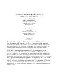
Let us calculate the kinetics parameters, the coupling coefficients analytically. The system<br />
is assumed to be a coupled reactor of two symmetrical cores shown in Fig.1 in order to<br />
compare the result with the previous one6) . Equation (4) for the importance function to<br />
produce fission neutrons becomes<br />
<br />
−D d2<br />
<br />
+ Σa Gm(x) =νΣfδm(x), (111)<br />
dx2 where cross sections are assumed to be region-wise constant. Solution of Eq.(111) in region<br />
V1 has a form<br />
⎧<br />
b1 sinh κr(x + a3), −a3 ≤ x ≤−a2<br />
⎪⎨ b2 cosh κcx + b3 sinh κcx +<br />
G1(x) =<br />
⎪⎩<br />
νΣfc<br />
, −a2 ≤ x ≤−a1<br />
Σac<br />
b4 cosh κrx + b5 sinh κrx, −a1 ≤ x ≤ a1,<br />
b6 cosh κcx + b7 sinh κcx, a1 ≤ x ≤ a2,<br />
b8 sinh κr(a3 − x), a2≤x≤a3, 14<br />
(112)
where κi =<br />
<br />
Σai/Di, i = c, r <strong>and</strong> constants bi, i =1, 2, ..., 8 are determined using the<br />
boundary conditions at the region boundary.<br />
We assume that the shape function for the neutron flux has a form of sine curve as<br />
f f<br />
1 (x) ∝ sin B(x + a2 + δ), −a2 ≤ x ≤−a1,<br />
f f<br />
2 (x) ∝ sin B(a2 − x + δ), a1 ≤ x ≤ a2.<br />
(113)<br />
For simplicity, we assume that φ 0<br />
Gm(x) ∝ f s m(x) = f f m(x), f c m(x) = 1, for c = I,X,C,<br />
X 0 (r) = constant, I 0 (r) = constant. Using these approximations, the coupling coefficients<br />
of Eq.(29) are obtained as<br />
k 0 11 = k s B<br />
11 =<br />
(B2 + κ2 c ) (cos Bδ − cos B(a2 − a1 + δ))<br />
×{cosh κca2 (Bb2 cos Bδ − κcb3 sin Bδ)<br />
− cosh κca1 (Bb2 cos B(a2 − a1 + δ) − κcb3 sin B(a2 − a1 + δ))<br />
+ sinh κca2 (κcb2 sin Bδ − Bb3 cos Bδ)<br />
− sinh κca1 (κcb2 sin B(a2 − a1 + δ) − Bb3 cos B(a2 − a1 + δ))} + νΣf<br />
, (114)<br />
Σa<br />
k 0 12 = ks 12 =<br />
B<br />
(B2 + κ2 c ) (cos Bδ − cos B(a2 − a1 + δ))<br />
×{cosh κca2 (Bb6 cos Bδ + κcb7 sin Bδ)<br />
− cosh κca1 (Bb6 cos B(a2 − a1 + δ)+κcb7 sin B(a2 − a1 + δ))<br />
+ sinh κca2 (κcb6 sin Bδ + Bb7 cos Bδ)<br />
− sinh κca1 (κcb6 sin B(a2 − a1 + δ)+Bb7 cos B(a2 − a1 + δ))} . (115)<br />
Since the system is assumed to be symmetric with respect to the origin at x = 0, other<br />
coupling coefficients k22 <strong>and</strong> k21 are equal to k11 <strong>and</strong> k12, respectively.<br />
3..2 NUMERICAL EXAMPLES<br />
Using equations derived in the preceding section, the xenon oscillation was analyzed <strong>and</strong><br />
the control method was investigated for the coupled reactors shown in Fig.1. The thickness<br />
of outer reflectors is assumed to be a3 − a2 = 30cm for all cases. The thickness of a core<br />
is adjusted such that the system becomes just critical with k = 1, <strong>and</strong> the change of the<br />
strength of the coupling between cores, damping time <strong>and</strong> period were calculated for several<br />
distances between cores. Constants used are shown in Table I, which were used in reference<br />
6. The leakage into the perpendicular direction was taken into account by using a buckling<br />
B 2 ⊥ =7.711 × 10 −3 cm −2 .<br />
The importance function G1(x) of Eq.(112) is shown in Fig.1 for the case of 2a1 =22.5cm.<br />
The steady state equation (62) was numerically solved together with Eqs.(63) <strong>and</strong> (64)<br />
15
Table I. One Group Constants 6)<br />
Moderator Core<br />
D (cm) 13.1 4.71<br />
Σa(cm −1 ) 0.0177 0.0829<br />
Σf(cm −1 ) 0.0594<br />
ν 2.44<br />
Xenon Iodine<br />
γ 0.003 0.061<br />
λ(s −1 ) 0.209 ×10 −4 0.287 ×10 −4<br />
σa(cm 2 ) 0.272 ×10 −17<br />
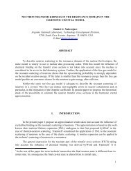
by the finite difference method, <strong>and</strong> the flux <strong>and</strong> xenon densities thus obtained are shown<br />
in Fig.2 for the same case of Fig.1, where the average flux φ 0<br />
1 = 5 × 1013cm−2sec−1 is<br />
used. From this figure, it is known that the assumption of sine shape <strong>and</strong> constant for<br />
the flux <strong>and</strong> xenon respectively, is reasonable. The critical thickness, coupling coefficients,<br />
damping time constant p <strong>and</strong> period are shown in Table II. In the coupled reactor theory,<br />
B =6.92 × 10⁻²cm−1 <strong>and</strong> δ=3.68cm are used in Eq.(113) for all cases, which are obtained<br />
by fitting the sine function of Eq.(113) to the numerical values of the flux obtained by the<br />
finite difference method.<br />
Table II. Critical Thickness, Coupling Coefficients, Damping Constant <strong>and</strong> Period<br />
2a a)<br />
1 Critical Thickness (cm) k11 k12 1/p Period<br />
(cm) FD Method b) CR Theory c) (×10 −2 ) (h) (h)<br />
10 33.99 33.87 0.37% d) 0.9829 3.94 3.73 — e)<br />
15 35.87 35.80 0.22% 1.0016 2.11 4.78 46.1<br />
20 36.79 36.75 0.12% 1.0109 1.21 8.73 27.4<br />
22.5 37.08 37.04 0.12% 1.0137 0.931 21.1 24.5<br />
25 37.29 37.25 0.09% 1.0159 0.720 −26.5 23.9<br />
a) Distance between cores b) Finite difference method c) Coupled reactor theory<br />
d) Difference from the finite difference method e) No oscillation<br />
As seen in Table II, the critical thickness by the coupled reactor theory approaches those<br />
by the finite difference method, as the distance between cores becomes larger. This may be<br />
due to the fact that one core becomes more independent of the other one as the distance<br />
between cores becomes larger, <strong>and</strong> the flux shape approaches to a pure sine shape. As shown<br />
in Table II, the coupling coefficient k12 becomes smaller, as the distance between cores, 2a1,<br />
becomes larger, then the xenon instability becomes larger.<br />
In the present approximations, ∆1 + ∆2 =2k 0 12. The conditions of Eqs.(89) <strong>and</strong> (91) for the<br />
16
Importance Function G1(x) G1(x)<br />
1<br />
0.5<br />
0<br />
–a3<br />
Reflector Core 1 Moderator Core 2 Reflector<br />
–a2<br />
oscillation <strong>and</strong> divergence become<br />
–a1<br />
a1 a2 a3<br />
–50 0 50<br />
Distance from the center of the syatem (cm)<br />
Figure 1. Importance function G1(x)<br />
0.0043 = ∆−<br />
2
Neutron Flux (cm –2 sec –1 )<br />
1×10 14<br />
5×10 13<br />
–a3<br />
Reflector Core 1 Moderator<br />
Neutron Flux<br />
–a2<br />
Xenon density<br />
0<br />
–80 –60 –40 –20 0<br />
Distance from the center of the system (cm)<br />
–a1<br />
2×10 15<br />
1.5×10 15<br />
1×10 15<br />
5×10 14<br />
Figure 2. Neutron flux <strong>and</strong> xenon density distributions for a steady state<br />
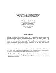
Difference of Axial Offsets<br />
0.01<br />
0.005<br />
0<br />
–0.005<br />
–0.01<br />
A<br />
C<br />
B<br />
Control Rod<br />
AOP–AOX<br />
AOI–AOX<br />
0 10 20 30<br />
Time (hours)<br />
E<br />
D<br />
F<br />
Control Rod<br />
0<br />
1×10 –5<br />
0<br />
–1×10 –5<br />
Figure 3. Time variations of AOP − AOX <strong>and</strong> AOI − AOX for t3 = 25h<br />
18<br />
Xenon density (cm –3 )<br />
Control Rod’s Cross Section (cm –1 )
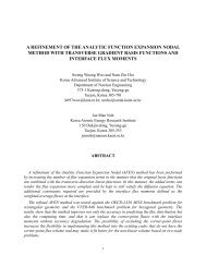
AOI–AOX<br />
0.002<br />
0<br />
–0.002<br />
B C<br />
A<br />
D E<br />
–0.004<br />
–0.01 –0.005 0 0.005<br />
AOP–AOX<br />
Figure 4. Trajectory of axial offset for t3 = 25h<br />
2. A point of offsets moves anticlockwise on the trajectory as a function of time.<br />
3. A point of offsets moves quickly horizontally parallel to the horizontal axis by insertion<br />
or withdrawal of control rods.<br />
The reason responsible for item 3 is the fact that the neutron production rate changes very<br />
quickly with time constant ω0 as seen in Eq.(100), while iodine <strong>and</strong> xenon densities change<br />
very slowly.<br />
In order to terminate the xenon oscillation, t3 = 25h or t3 = 28h was put in Eq.(107), <strong>and</strong><br />
t4 =27.6h <strong>and</strong> δΣ C2 = −1.85 × 10 −6 cm −1 or t4 =55.4h <strong>and</strong> δΣ C2 = −3.74 × 10 −7 cm −1 were<br />
obtained for the cases of Figs.3 <strong>and</strong> 5, respectively. Using these values, the xenon oscillations<br />
are completely terminated as seen in Figs.3 <strong>and</strong> 5.<br />
In Fig.4, for example, the point of offsets moved in negative direction from the origin to A<br />
almost parallel to the horizontal axis in a short time by withdrawal of a control rod, <strong>and</strong><br />
move in positive direction quickly from point B to C by returning the control rod to the<br />
original position. At the time t3 chosen appropriately, the rod is inserted <strong>and</strong> the point<br />
moved quickly in positive direction from point D to E, <strong>and</strong> at time t4, the point moved<br />
quickly from point F to the origin <strong>and</strong> the oscillation is terminated. The distance from<br />
point F to the origin is nearly the same as that from point D to E. In Figs.3 <strong>and</strong> 5, the<br />
difference between the time t3, 25h <strong>and</strong> 28h for the insertion of control rods is 3h, however,<br />
the difference of the time t4, 27.6h <strong>and</strong> 55.4h for the withdrawal between both cases is fairly<br />
large.<br />
19<br />
O<br />
F
Difference of Axial Offsets<br />
AOI–AOX<br />
0.01<br />
0.005<br />
0<br />
–0.005<br />
–0.01<br />
A<br />
C<br />
B<br />
Control Rod<br />
AOP–AOX<br />
AOI–AOX<br />
E<br />
D<br />
Control Rod<br />
0 20 40 60<br />
Time (hours)<br />
F<br />
1×10 –5<br />
0<br />
–1×10 –5<br />
Figure 5. Time variations of AOP − AOX <strong>and</strong> AOI − AOX for t3 = 28h<br />
0.002<br />
0<br />
–0.002<br />
B C<br />
A<br />
OF<br />
–0.004<br />
–0.01 –0.005 0 0.005<br />
AOP–AOX<br />
D E<br />
Figure 6. Trajectory of axial offsets for t3 = 28h<br />
20<br />
Control Rod’s Cross Section (cm –1 )
CONCLUSIONS<br />
It has been shown that the two-point kinetics equations which are derived using the regionwise<br />
importance functions to produce fission neutrons can be used to analyze the xenon<br />
spatial oscillation. Using these kinetics equations, the timing <strong>and</strong> magnitude for movement<br />
of control rods to terminate the xenon oscillation can be calculated in terms of kinetics<br />
parameters without using any empirical values.<br />
Although numerical examples are given for simple one-group problems of one-dimensional<br />
slab geometry, the formulation is given for multi-group <strong>and</strong> 3 dimensional form, <strong>and</strong> there will<br />
be no difficulties for such problems in calculating kinetics parameters of two-point kinetics<br />
equations using the conventional multi-group diffusion or transport programs for a steady<br />
state.<br />
ACKNOWLEDGEMENTS<br />
The authors wish to express their sincere thanks to Dr. E. Kiefhaber of Forschungszentrum<br />
Karlsruhe for his many useful comments to the manuscript.<br />
REFERENCES<br />
1) W.M.Stacey, ”Linear Analysis of Xenon Spatial Oscillation”, Nucl. Sci. Eng. 30, 453,<br />
(1967).<br />
2) A.M. CHRISTIE <strong>and</strong> C.G. PONCELET, ”On the Control of Spatial Xenon Oscillations”,<br />
Nucl. Sci. Eng. 51, 10 (1973).<br />
3) N.Z. Chao <strong>and</strong> L.M. Grossman, ”Optimal Control Spatial Oscillations in Load Follow<br />
of a Nuclear Reactor”, Nucl. Sci. Eng. 83, 136, (1983).<br />
4) J.D. Teachman <strong>and</strong> R.J. Onega, ”The Influence of Energy Group Structure <strong>and</strong> Nonlinearities<br />
on the Calculation of Xenon-Induced Flux Oscillations”, Nucl. Sci. Eng. 83,<br />
149, (1983).<br />
5) C. Lin <strong>and</strong> Y. Lin, ”Control of Spatial Xenon Oscillations in Pressurized Water Reactors<br />
Via the Kalman Filter”, Nucl. Sci. Eng. 118, 1260, (1994).<br />
6) K. <strong>Kobayashi</strong> <strong>and</strong> M. Yoshikuni, ”Analysis of Xenon Oscillation by Coupled Reactor<br />
Model”, J. Nucl. Sci. Technol. 19, 107-118 (1982).<br />
7) K. <strong>Kobayashi</strong>, ”Rigorous Derivation of Multi-Point Reactor Kinetics Equations with<br />
Explicit Dependence on Perturbation”, J. Nucl. Sci. Technol., 29, 110-120 (1992).<br />
8) Y. Nagaya <strong>and</strong> K. <strong>Kobayashi</strong>, ”Solution of 1-D Multi-Group Time Dependent Diffusion<br />
Equations Using the Coupled Reactors Theory”, Ann. Nucl. Energy, 22, 421-440 (1995).<br />
9) Y. Shimazu, ”Direct Method of Search of Optimal Xenon Oscillation Control Based on<br />
New Concept of Axial Offsets”, J. Nucl. Sci. Technol., 29, 966-971 (1992).<br />
10) Y. Shimazu, ”Continuous Guidance Procedure for Xenon Oscillation Control”, J. Nucl.<br />
Sci. Technol., 32, 95-100 (1995).<br />
21