Fractional potential field in path planning for mobile robot obstacle ...
Fractional potential field in path planning for mobile robot obstacle ...
Fractional potential field in path planning for mobile robot obstacle ...

You also want an ePaper? Increase the reach of your titles
YUMPU automatically turns print PDFs into web optimized ePapers that Google loves.
<strong>Fractional</strong> <strong>potential</strong> <strong>field</strong> <strong>in</strong> <strong>path</strong> plann<strong>in</strong>g <strong>for</strong> <strong>mobile</strong> <strong>robot</strong> <strong>obstacle</strong><br />
avoidance <strong>in</strong> the feedback control of a diffusion process<br />
Zhongm<strong>in</strong> Wang<br />
Center <strong>for</strong> Self-Organiz<strong>in</strong>g and Intelligent Systems<br />
Dept. of Electrical and Computer Eng<strong>in</strong>eer<strong>in</strong>g<br />
Utah State University<br />
April 19, 2005<br />
1 - 15
References<br />
• Jorge Cortes, Sonia Mart<strong>in</strong>ez, Timur Karatas and Francesco Bullo,<br />
“Coverage Control <strong>for</strong> Mobile Sens<strong>in</strong>g Networks”, IEEE Trans on Robotics<br />
and Automation, Vol.20, NO.2, April 2004.<br />
• Lili Ju, Qiang Du and Max Gunzburger, “Probabilistic methods <strong>for</strong> centroidal<br />
Voronoi tessellations and their parallel implementtaions”,Journal of Parallel<br />
Comput<strong>in</strong>g,Volume 28 , Issue 10, October 2002, Pages: 1477<br />
• S. S GE and Y. J. CUI, “Dyanmic motiong plann<strong>in</strong>g <strong>for</strong> <strong>mobile</strong> <strong>robot</strong>s us<strong>in</strong>g<br />
potentail <strong>field</strong> method”, Autonomous Robots,Volume 13, 2002,<br />
pages:207–222.<br />
• A.Poty, P. Melchior and A. Oustaloup, “Dynamic <strong>path</strong> plann<strong>in</strong>g <strong>for</strong> <strong>mobile</strong><br />
<strong>robot</strong>s us<strong>in</strong>g fractional <strong>potential</strong> filed”, <strong>in</strong> Proceed<strong>in</strong>gs of First International<br />
Symposium on Control, Communications and Signal Process<strong>in</strong>g, 2004,<br />
Page(s):557 - 561.<br />
2 - 15
Coulombian Potential Field<br />
The <strong>potential</strong> <strong>field</strong> method is widely used <strong>for</strong> autonomous <strong>mobile</strong> <strong>robot</strong> <strong>path</strong> plann<strong>in</strong>g<br />
due to its elegant mathematical analysis and simplicity [3]. The coulombian<br />
electric <strong>field</strong> E(r) generated by a punctual charge <strong>in</strong> the vacuum is given by:<br />
E(r) =<br />
q<br />
4πε0r 2er.<br />
where ε0 is vacuum permittivity, r is the distance to charge q, and er a radial unit<br />
vector. A s<strong>in</strong>gle <strong>in</strong>tegration provides the coulombian <strong>potential</strong> from the electric<br />
<strong>field</strong> of a punctual charge:<br />
V (r) = q<br />
4πε0r .<br />
We can use two <strong>in</strong>tegration and more to set up the <strong>potential</strong> filed.<br />
3 - 15
<strong>Fractional</strong> Potential Field<br />
The fractional <strong>potential</strong> def<strong>in</strong>ition us<strong>in</strong>g the Weyl fractional <strong>in</strong>tegral is given below:<br />
Vn(r) = W r ∞<br />
q (θ − r)<br />
E(r) =<br />
4πε0Γ(n)<br />
n−1<br />
r2 dθ.<br />
where Γ(n) is the Gamma function def<strong>in</strong>ed by:<br />
Γ(n) =<br />
1<br />
0<br />
r<br />
[ln( 1<br />
t )]n−1 dt.<br />
The fractional <strong>potential</strong> is then normalized between 0 and 1. It has a maximum<br />
effective distance rmax. To avoid the s<strong>in</strong>gularity at r = 0, a m<strong>in</strong>imum distance<br />
rm<strong>in</strong> should also be chosen.<br />
∀n ∈ [0, 2[, ∀r ∈ [rm<strong>in</strong>, rmax],<br />
Un(r) = Vn(r) − Vn(rmax)<br />
Vn(rm<strong>in</strong>) − Vn(rmax) = rn−2 − rn−2 max<br />
rn−2 m<strong>in</strong> − rn−2 .<br />
max<br />
n is the risk coefficients.<br />
4 - 15
FRACTIONAL POTENTIAL FIELD IN PATH PLANNING FOR MOBILE<br />
AVOIDANCE OF DYNAMIC OBS<br />
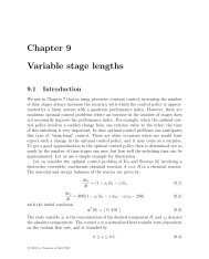
Normalized fractional <strong>potential</strong><br />
1<br />
0.9<br />
0.8<br />
0.7<br />
0.6<br />
0.5<br />
0.4<br />
0.3<br />
0.2<br />
0.1<br />
n=2: segment<br />
n=1: ponctual charge<br />
0<br />
0 5 10 15 20 25 30<br />
r =1 r<br />
m<strong>in</strong> Distance<br />
=30<br />
max<br />
1: Influence • n = 1 gives distance the Coulombian of the normalized <strong>potential</strong> <strong>field</strong>fractional generated by <strong>potential</strong> an isolated based charge. on We<br />
n (1 •≤ n n= ≤2 gives 5 ); the coulombian Coulombian <strong>potential</strong> <strong>field</strong> created generated by by a uni<strong>for</strong>mly punctualdistributed charge (n=1<br />
mly distributed charge along charge a straight-l<strong>in</strong>e on a segment segment. (n=2)<br />
5 - 15<br />
n=4<br />
n=3
ALEXANDRE POTY, PIERRE MELCHIOR AND ALAIN OUSTALOUP<br />
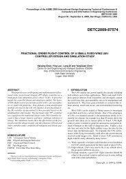
Figure 3: <strong>Fractional</strong> map 3D example - the height is the danger level<br />
2.3 <strong>Fractional</strong> road<br />
• The risk coefficients are fixed at 1.2 <strong>for</strong> the square, 1.5 <strong>for</strong> the chamfered<br />
rectangle and 2.5 <strong>for</strong> the circle. rmax = 20 and rm<strong>in</strong> = 1.<br />
The operator chooses a threshold of danger level beyond which it estimates that the risk<br />
taken by the <strong>robot</strong> would be too important. An horizontal cross section of the fractional<br />
card at the given threshold 4, provides some equi<strong>potential</strong> which separates zones where<br />
the danger is too important, from zones of security to be used [27].<br />
6 - 15
Feedback control of a diffusion process - pollution neutralization<br />
We consider the pollution neutralization problem. The scenario is described as<br />
follows:<br />
• A toxic diffusion source is releas<strong>in</strong>g toxic material <strong>in</strong> 2D plane. The diffusion<br />
process is modelled as a parabolic PDE system.<br />
• Chemical concentration sensors are deployed to cover the polluted area and<br />
collect data about the pollution.<br />
• A few of <strong>mobile</strong> <strong>robot</strong>s equipped with controllable dispensers of neutraliz<strong>in</strong>g<br />
chemicals are sent to the polluted area with the mission to elim<strong>in</strong>ate the<br />
pollution by properly releas<strong>in</strong>g the neutraliz<strong>in</strong>g chemicals.<br />
Problem: How to choose the optimal positions <strong>for</strong> these <strong>robot</strong>s and the trajectories<br />
the <strong>robot</strong>s will follow when the dynamic diffusion is evolv<strong>in</strong>g?<br />
7 - 15
Optimal Actuator location <strong>in</strong> feedback control of diffusion process<br />
Let Ω be a convex polytope <strong>in</strong> R2 , <strong>in</strong>clud<strong>in</strong>g its <strong>in</strong>terior. A concentration function<br />
is a map ρ(x, y) : Ω → R+ that represents the pollutant concentration over Ω.<br />
To simplify the presentation of our ma<strong>in</strong> idea, <strong>in</strong> our simulation experiment, we<br />
assume ρ(x, y) is governed by the follow<strong>in</strong>g PDE system:<br />
2 ∂ρ ∂ ρ<br />
= k<br />
∂t ∂x2 + ∂2ρ ∂y2 <br />
+ fd(ρ, x, y, t), (1)<br />
where k is a constant positive real system parameter; fd(ρ, x, y, t) represents the<br />
source of the pollution. We assume that the diffusion process is evolv<strong>in</strong>g slowly.<br />
Let P = (p1, · · · , pn) be the location of n actuators and let | · | denote the<br />
Euclidean distance function. Every <strong>robot</strong> at pi will receive <strong>in</strong><strong>for</strong>mation of sensors<br />
and release the neutralization chemical by some control law.<br />
8 - 15
The objectives are:<br />
• Control the diffusion of the pollution to a conf<strong>in</strong>ed area.<br />
• Neutralize the pollution <strong>in</strong> a time optimal way while not mak<strong>in</strong>g the area overdosed.<br />
• M<strong>in</strong>imize the polluted area that is heavily affected.<br />
n <strong>robot</strong>s will partition Ω <strong>in</strong>to a collection of n polytopes V = {V1, · · · , Vn},<br />
pi ∈ Vi. It can be seen that to control the diffusion process and m<strong>in</strong>imize the<br />
heavily affected area, the <strong>robot</strong>s should be close to those areas with high pollution<br />
concentrations. To decide the positions of the <strong>robot</strong>s, we consider the m<strong>in</strong>imiz<strong>in</strong>g<br />
of the follow<strong>in</strong>g cost function.<br />
K(P, V) =<br />
n<br />
<br />
i=1<br />
Vi<br />
ρ(q)|q − pi| 2 dq <strong>for</strong> q ∈ Ω. (2)<br />
It is clear that to m<strong>in</strong>imize K, the distance |q − pi| should be small when the<br />
pollution concentration ρ(q) is big. A necessary condition <strong>for</strong> K to be m<strong>in</strong>imized<br />
is that {pi, Vi} k i=1 is a Centroidal Voronoi Tessellation of Ω<br />
9 - 15
Example:<br />
z ∗ i =<br />
<br />
Vi xρ(x)dx<br />
We call the tessellation def<strong>in</strong>ed by (3) a Centroidal Voronoi Tessellation if and only if<br />
Vi<br />
ρ(x)dx <strong>for</strong> i = 1, · · · , k. (4)<br />
zi = z ∗ i <strong>for</strong> i = 1, · · · , k.<br />
So, the po<strong>in</strong>ts zi that serves as the generators <strong>for</strong> the Voronoi regions Vi are themselves the mass centroids of those regions,<br />
as shown <strong>in</strong> Fig. 1(b).<br />
0.8<br />
0.6<br />
0.4<br />
0.2<br />
0<br />
−0.2<br />
−0.4<br />
−0.6<br />
−0.8<br />
−0.8 −0.6 −0.4 −0.2 0 0.2 0.4 0.6 0.8<br />
(a) The Voronoi regions constructed by 100 randomly selected<br />
po<strong>in</strong>ts <strong>in</strong> a square Ω = (−1, 1) 2 . The density function<br />
is given by ρ(x, y) = e −8(x2 +y 2 ) . The dots are the Voronoi<br />
generators and the circles are the mass centroids of the<br />
correspond<strong>in</strong>g Voronoi regions. The generators and the mass<br />
centroids do not co<strong>in</strong>cide.<br />
0.8<br />
0.6<br />
0.4<br />
0.2<br />
0<br />
−0.2<br />
−0.4<br />
−0.6<br />
−0.8<br />
−0.6 −0.4 −0.2 0 0.2 0.4 0.6<br />
(b) The centroidal Voronoi tessellations constructed by 100<br />
po<strong>in</strong>ts <strong>in</strong> the same Ω and same density function ρ as <strong>in</strong><br />
1(a). These po<strong>in</strong>ts server both as the generators and the<br />
mass centroids of the correspond<strong>in</strong>g regions. More of them<br />
aggregate to area where ρ(x, y) is bigger.<br />
Fig. 1. The illustration of Voronoi diagram and Centroidal Voronoi Tessellations.<br />
Centroidal Voronoi Tessellation has broad applications <strong>in</strong> many <strong>field</strong>s. It is the solution to optimal placement of resources,<br />
but <strong>in</strong> general, CVT can only be approximately constructed. For algorithms to implement CVT, refer to [14]. In [12], an<br />
example is given to show how CVT can be used to predict the cell divisions. It is shown that, after the cell division process,<br />
the new cells’ shapes are very closely approximated10by- 15<br />
Centroidal Voronoi Tessellations correspond<strong>in</strong>g to the <strong>in</strong>creased<br />
number of generators. This is an example to show how CVT can be applied <strong>in</strong> a dynamically evolv<strong>in</strong>g environment.
Collision Avoidance<br />
Now we consider the safety issue of the <strong>mobile</strong> <strong>robot</strong>. It is highly likely that the<br />
<strong>robot</strong> will encounter mov<strong>in</strong>g <strong>obstacle</strong>s that travel through the polluted area, <strong>for</strong> example,<br />
the mov<strong>in</strong>g cargo vessels. In order to avoid collision between the <strong>robot</strong> and<br />
the mov<strong>in</strong>g <strong>obstacle</strong> effectively, the relative position and velocity between <strong>robot</strong><br />
and <strong>obstacle</strong> should be considered. Here we <strong>in</strong>troduce a <strong>potential</strong> <strong>field</strong> method<br />
from reference 3 that is used <strong>for</strong> dynamic <strong>obstacle</strong> avoidance.<br />
The repulsive <strong>potential</strong> generated by the <strong>obstacle</strong> is given by:<br />
Urep(p, v) =<br />
⎧<br />
⎪⎨<br />
⎪⎩<br />
0 :<br />
if ρs(p, p obs) − ρm ≥ ρ0 or vRO ≤ 0<br />
η(Urep) :<br />
if 0 < ρs(p, p obs) − ρm < ρm and vRO > 0<br />
undef<strong>in</strong>ed :<br />
if vRO > 0 and ρs(p, p obs) < ρm<br />
The positive <strong>for</strong>ce between the <strong>robot</strong> and the <strong>obstacle</strong> is def<strong>in</strong>ed as the negative<br />
gradient of the repulsive <strong>potential</strong> with respect to <strong>robot</strong> position and velocity.<br />
11 - 15<br />
(3)
Let nRO⊥ be the unit vector perpendicular to nRO and n T RO⊥nRO⊥ = 1. The positive<br />
<strong>for</strong>ce between the <strong>robot</strong> and the <strong>obstacle</strong> is def<strong>in</strong>ed as the negative gradient of<br />
the repulsive <strong>potential</strong> with respect to the <strong>robot</strong> position and velocity:<br />
⎧<br />
where:<br />
and<br />
Frep(p, v) =<br />
where vRO⊥ is given by<br />
⎪⎨<br />
⎪⎩<br />
0 :<br />
if ρs(p, p obs) − ρm ≥ ρ0 or vRO ≤ 0<br />
Frep1 + Frep2 :<br />
if 0 < ρs(p, p obs) − ρm < ρm and vRO > 0<br />
undef<strong>in</strong>ed :<br />
if vRO > 0 and ρs(p, p obs) < ρm<br />
Frep1 = −ηU 2<br />
rep(1 + vRO<br />
)nRO.<br />
amax<br />
Frep2 = ηU 2 repvROvRO⊥<br />
nRO⊥.<br />
ρs(p, pobs)amax vRO⊥ = v(t) − vobs 2 −v 2 RO(t).<br />
12 - 15<br />
(4)
The <strong>mobile</strong> <strong>robot</strong>s are treated as virtual particles with unit mass and obey the<br />
second-order dynamical equation:<br />
where the control <strong>in</strong>put Fi is given by<br />
¨pi = Fi<br />
Fi = fi − kv ˙pi + Frep<br />
with fi the <strong>for</strong>ce <strong>in</strong>put to control the motion of the <strong>robot</strong> by CVT. fi is given by a<br />
proportional control law:<br />
fi = −k(pi − ¯pi)<br />
where ¯pi is the computed mass centroid of the current Voronoi cell.<br />
13 - 15<br />
(5)
Simulation implementation<br />
Diff-MAS2D is used as the simulation plat<strong>for</strong>m <strong>for</strong> our implementation. The<br />
area concerned is given by Ω = {(x, y)|0 ≤ x ≤ 1, 0 ≤ y ≤ 1}. The PDE<br />
system with control <strong>in</strong>put is modelled as<br />
∂ρ(x, y, t)<br />
∂t<br />
= k( ∂2 ρ(x, y, t)<br />
∂x 2<br />
where k = 0.01 and the boundary condition is given by<br />
+ ∂2 ρ(x, y, t)<br />
∂y 2 ) + fc(x, y, t) + fd(x, y, t), (6)<br />
∂u<br />
∂n<br />
= 0.<br />
The stationary pollution source is modelled as a po<strong>in</strong>t disturbance fd to the the<br />
PDE system with its position at (0.75, 0.35) and<br />
fd(t) = 20e −t |(x=0.75,y=0.35).<br />
14 - 15
0.1. Question ?<br />
15 - 15