Simulation of Doubly-Fed Induction Generator in a Wind Turbine XI ...
Simulation of Doubly-Fed Induction Generator in a Wind Turbine XI ...
Simulation of Doubly-Fed Induction Generator in a Wind Turbine XI ...

Create successful ePaper yourself
Turn your PDF publications into a flip-book with our unique Google optimized e-Paper software.
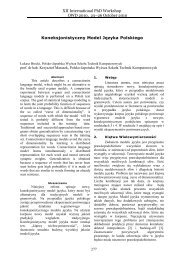
For a lossless generator the mechanical equation is:<br />
<br />
<br />
In steady-state for a lossless generator we have:<br />
<br />
from where it follows:<br />
<br />
where <br />
generator.<br />
<br />
<br />
is def<strong>in</strong>ed as the slip <strong>of</strong> the<br />
Generally the absolute value <strong>of</strong> slip is much lower<br />
than 1 and consequently P r is only a fraction <strong>of</strong> P s .<br />
S<strong>in</strong>ce T m is positive for power generation and s<strong>in</strong>ce<br />
ω s is positive and constant for a constant frequency<br />
grid voltage, the sign <strong>of</strong> P r is a function <strong>of</strong> the slip<br />
sign. P r is positive for negative slip<br />
(super-synchronous speed) and it is negative for<br />
positive slip (sub-synchronous speed). For supersynchronous<br />
speed operation P r is transmitted to DC<br />
bus capacitor and tends to rise the DC voltage. For<br />
sub-synchronous speed operation, P r is taken out <strong>of</strong><br />
DC bus capacitor and tends to decrease the DC<br />
voltage. C grid is used to generate or absorb the power<br />
P gc <strong>in</strong> order to keep the DC voltage constant. In<br />
steady-state for a lossless AC/DC/AC converter P gc<br />
is equal to P r and the speed <strong>of</strong> the w<strong>in</strong>d turb<strong>in</strong>e is<br />
determ<strong>in</strong>ed by the power P r absorbed or generated<br />
by C rotor .<br />
The phase-sequence <strong>of</strong> the AC voltage generated<br />
by C rotor is positive for sub-synchronous speed and<br />
negative for super-synchronous speed. The<br />
frequency <strong>of</strong> this voltage is equal to the product <strong>of</strong><br />
the grid frequency and the absolute value <strong>of</strong> the slip.<br />
C rotor and C grid have the capability for generat<strong>in</strong>g or<br />
absorb<strong>in</strong>g reactive power and could be used to<br />
control the reactive power or the voltage at the grid<br />
term<strong>in</strong>als.<br />
Fig.2. Active and reactive power flows<br />
379<br />
1.1 Mathematical model <strong>of</strong> the DFIG<br />
For a doubly-fed <strong>in</strong>duction mach<strong>in</strong>e, the Park<br />
transformation’s application to the traditional a,b,c<br />
model allows to write a dynamic model <strong>in</strong> a d-q<br />
reference frame as follows:<br />
<br />
<br />
<br />
<br />
<br />
<br />
<br />
<br />
<br />
<br />
<br />
<br />
<br />
<br />
<br />
<br />
<br />
<br />
The stator and rotor fluxes can be expressed:<br />
<br />
<br />
<br />
<br />
<br />
<br />
<br />
The mechanical and electromagnetic torque are<br />
expressed with the follow<strong>in</strong>g equations:<br />
<br />
<br />
<br />
<br />
The active and reactive powers at the stator are<br />
def<strong>in</strong>ed as:<br />
<br />
<br />
Also the active and reactive powers at the rotor :<br />
<br />
<br />
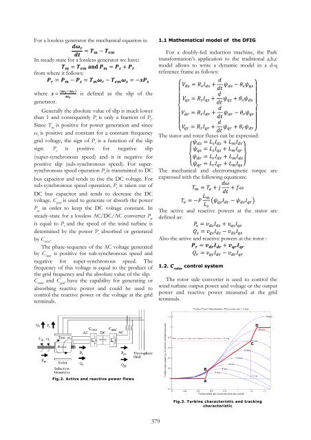
1.2. C rotor control system<br />
The rotor side converter is used to control the<br />
w<strong>in</strong>d turb<strong>in</strong>e output power and voltage or the output<br />
power and reactive power measured at the grid<br />
term<strong>in</strong>als.<br />
B<br />
A<br />
Fig.3. Turb<strong>in</strong>e characteristic and track<strong>in</strong>g<br />
characteristic<br />
C<br />
D