Simulation of Doubly-Fed Induction Generator in a Wind Turbine XI ...
Simulation of Doubly-Fed Induction Generator in a Wind Turbine XI ...
Simulation of Doubly-Fed Induction Generator in a Wind Turbine XI ...

You also want an ePaper? Increase the reach of your titles
YUMPU automatically turns print PDFs into web optimized ePapers that Google loves.
<strong>Simulation</strong> <strong>of</strong> <strong>Doubly</strong>-<strong>Fed</strong> <strong>Induction</strong> <strong>Generator</strong><br />
<strong>in</strong> a W<strong>in</strong>d Turb<strong>in</strong>e<br />
Branislav Dosijanoski, M.Sc. Student, Faculty <strong>of</strong> Electrical Eng<strong>in</strong>eer<strong>in</strong>g and Information Technologies, University Ss.<br />
Cyril & Methodius, Skopje.<br />
Abstract<br />
In order to meet power needs, tak<strong>in</strong>g <strong>in</strong>to<br />
account economical and environmental factors, w<strong>in</strong>d<br />
energy conversion is gradually ga<strong>in</strong><strong>in</strong>g <strong>in</strong>terests as a<br />
suitable source <strong>of</strong> renewable energy. In a country like<br />
m<strong>in</strong>e where there is not a s<strong>in</strong>gle kW <strong>in</strong>stalled w<strong>in</strong>d<br />
energy, the question is, How to simulate and explore<br />
the transients <strong>of</strong> these variable speed devices? This<br />
paper deals with simulation <strong>of</strong> a W<strong>in</strong>d Turb<strong>in</strong>e based<br />
on a doubly-fed <strong>in</strong>duction mach<strong>in</strong>e used <strong>in</strong><br />
generat<strong>in</strong>g mode to produce electrical energy on a<br />
power network. A mathematical model <strong>of</strong> the<br />
mach<strong>in</strong>e is written <strong>in</strong> appropriate d-q reference<br />
frame is established to <strong>in</strong>vestigate simulations.<br />
1. Introduction<br />
Large W<strong>in</strong>d turb<strong>in</strong>es are <strong>of</strong>ten equipped with<br />
doubly-fed <strong>in</strong>duction generators. There are several<br />
advantages by us<strong>in</strong>g adjustable speed generators.<br />
Modern w<strong>in</strong>d turb<strong>in</strong>es use complex technologies<br />
<strong>in</strong>clud<strong>in</strong>g power electronic converters and<br />
sophisticated control systems. Electromagnetic<br />
transients need to be simulated and analyzed <strong>in</strong> order<br />
to study the impact <strong>of</strong> these generators on the power<br />
systems. Methods and tools for simulation <strong>of</strong> w<strong>in</strong>d<br />
turb<strong>in</strong>es <strong>in</strong> large power systems are therefore needed.<br />
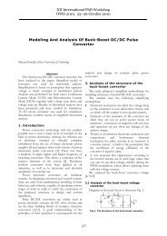
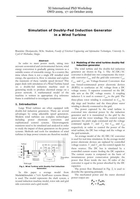
Fig.1. W<strong>in</strong>d Turb<strong>in</strong>e with <strong>Doubly</strong>-<strong>Fed</strong> <strong>Induction</strong><br />
<strong>Generator</strong>.<br />
In this paper a average model from<br />
Matlab&Simul<strong>in</strong>k v.7.6.0. SymPower systems library<br />
is used. The model represents the shaft system, a<br />
wound <strong>in</strong>duction mach<strong>in</strong>e model, rotor side and grid<br />
side converters and a grid model.<br />
<strong>XI</strong> International PhD Workshop<br />
OWD 2009, 17–20 October 2009<br />
378<br />
1.1 Model<strong>in</strong>g <strong>of</strong> the w<strong>in</strong>d turb<strong>in</strong>e doubly-fed<br />
<strong>in</strong>duction generator<br />
The w<strong>in</strong>d turb<strong>in</strong>e and the doubly-fed <strong>in</strong>duction<br />
generator are shown <strong>in</strong> Fig. 1. The AC/DC/AC<br />
converter is divided <strong>in</strong>to two components: the rotorside<br />
converter C rotor and the grid-side converter C grid .<br />
C rotor and C grid are Voltage-Sourced Converters that<br />
use forced-commutated power electronic devices<br />
(IGBTs) to synthesize an AC voltage from a DC<br />
voltage source. A capacitor connected on the DC<br />
side acts as the DC voltage source. A coupl<strong>in</strong>g<br />
<strong>in</strong>ductor L is used to connect C grid to the grid. The<br />
three-phase rotor w<strong>in</strong>d<strong>in</strong>g is connected to C rotor by<br />
slip r<strong>in</strong>gs and brushes and the three-phase stator<br />
w<strong>in</strong>d<strong>in</strong>g is directly connected to the grid.<br />
The power captured by the w<strong>in</strong>d turb<strong>in</strong>e is<br />
converted <strong>in</strong>to electrical power by the <strong>in</strong>duction<br />
generator and it is transmitted to the grid by the<br />
stator and the rotor w<strong>in</strong>d<strong>in</strong>gs. The control system<br />
generates the pitch angle command and the voltage<br />
command signals V r and V gc for C rotor and C grid<br />
respectively <strong>in</strong> order to control the power <strong>of</strong> the<br />
w<strong>in</strong>d turb<strong>in</strong>e, the DC bus voltage and the voltage at<br />
the grid term<strong>in</strong>als.<br />
An average model <strong>of</strong> the AC/DC/AC converter<br />
is used for real-time simulation. In the average model<br />
power electronic devices are replaced by controlled<br />
voltage sources. V r and V gc are the control signals for<br />
these sources. The DC bus is simulated by a<br />
controlled current source feed<strong>in</strong>g the DC capacitor.<br />
The current source is computed on the basis <strong>of</strong><br />
<strong>in</strong>stantaneous power conservation pr<strong>in</strong>ciple: the<br />
power that flows <strong>in</strong>side the two AC-sides <strong>of</strong> the<br />
converter is equal to the power absorbed by the DC<br />
capacitor.<br />
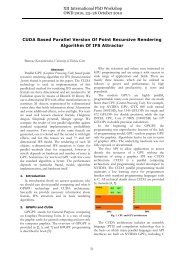
The power flow illustrated <strong>in</strong> Fig. 2, is used to<br />
describe the operat<strong>in</strong>g pr<strong>in</strong>ciple.<br />
The mechanical power and the stator electrical<br />
power output are:
For a lossless generator the mechanical equation is:<br />
<br />
<br />
In steady-state for a lossless generator we have:<br />
<br />
from where it follows:<br />
<br />
where <br />
generator.<br />
<br />
<br />
is def<strong>in</strong>ed as the slip <strong>of</strong> the<br />
Generally the absolute value <strong>of</strong> slip is much lower<br />
than 1 and consequently P r is only a fraction <strong>of</strong> P s .<br />
S<strong>in</strong>ce T m is positive for power generation and s<strong>in</strong>ce<br />
ω s is positive and constant for a constant frequency<br />
grid voltage, the sign <strong>of</strong> P r is a function <strong>of</strong> the slip<br />
sign. P r is positive for negative slip<br />
(super-synchronous speed) and it is negative for<br />
positive slip (sub-synchronous speed). For supersynchronous<br />
speed operation P r is transmitted to DC<br />
bus capacitor and tends to rise the DC voltage. For<br />
sub-synchronous speed operation, P r is taken out <strong>of</strong><br />
DC bus capacitor and tends to decrease the DC<br />
voltage. C grid is used to generate or absorb the power<br />
P gc <strong>in</strong> order to keep the DC voltage constant. In<br />
steady-state for a lossless AC/DC/AC converter P gc<br />
is equal to P r and the speed <strong>of</strong> the w<strong>in</strong>d turb<strong>in</strong>e is<br />
determ<strong>in</strong>ed by the power P r absorbed or generated<br />
by C rotor .<br />
The phase-sequence <strong>of</strong> the AC voltage generated<br />
by C rotor is positive for sub-synchronous speed and<br />
negative for super-synchronous speed. The<br />
frequency <strong>of</strong> this voltage is equal to the product <strong>of</strong><br />
the grid frequency and the absolute value <strong>of</strong> the slip.<br />
C rotor and C grid have the capability for generat<strong>in</strong>g or<br />
absorb<strong>in</strong>g reactive power and could be used to<br />
control the reactive power or the voltage at the grid<br />
term<strong>in</strong>als.<br />
Fig.2. Active and reactive power flows<br />
379<br />
1.1 Mathematical model <strong>of</strong> the DFIG<br />
For a doubly-fed <strong>in</strong>duction mach<strong>in</strong>e, the Park<br />
transformation’s application to the traditional a,b,c<br />
model allows to write a dynamic model <strong>in</strong> a d-q<br />
reference frame as follows:<br />
<br />
<br />
<br />
<br />
<br />
<br />
<br />
<br />
<br />
<br />
<br />
<br />
<br />
<br />
<br />
<br />
<br />
<br />
The stator and rotor fluxes can be expressed:<br />
<br />
<br />
<br />
<br />
<br />
<br />
<br />
The mechanical and electromagnetic torque are<br />
expressed with the follow<strong>in</strong>g equations:<br />
<br />
<br />
<br />
<br />
The active and reactive powers at the stator are<br />
def<strong>in</strong>ed as:<br />
<br />
<br />
Also the active and reactive powers at the rotor :<br />
<br />
<br />
1.2. C rotor control system<br />
The rotor side converter is used to control the<br />
w<strong>in</strong>d turb<strong>in</strong>e output power and voltage or the output<br />
power and reactive power measured at the grid<br />
term<strong>in</strong>als.<br />
B<br />
A<br />
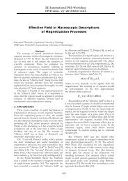
Fig.3. Turb<strong>in</strong>e characteristic and track<strong>in</strong>g<br />
characteristic<br />
C<br />
D
The power is controlled <strong>in</strong> order to follow a predef<strong>in</strong>ed<br />
power-speed characteristic named track<strong>in</strong>g<br />
characteristic. This characteristic is illustrated by the<br />
ABCD curve <strong>in</strong> Fig. 3 imposed to the mechanical<br />
power characteristics <strong>of</strong> the turb<strong>in</strong>e obta<strong>in</strong>ed at<br />
different w<strong>in</strong>d speeds. The actual speed <strong>of</strong> the<br />
turb<strong>in</strong>e ω r is measured and the correspond<strong>in</strong>g<br />
mechanical power <strong>of</strong> the track<strong>in</strong>g characteristic is<br />
used as the reference power for the power control<br />
loop. The track<strong>in</strong>g characteristic is def<strong>in</strong>ed by four<br />
po<strong>in</strong>ts: A, B, C and D. From zero speed to speed <strong>of</strong><br />
po<strong>in</strong>t A the reference power is zero. Between po<strong>in</strong>t<br />
A and po<strong>in</strong>t B the track<strong>in</strong>g characteristic is a straight<br />
l<strong>in</strong>e. Between po<strong>in</strong>t B and po<strong>in</strong>t C the track<strong>in</strong>g<br />
characteristic is the locus <strong>of</strong> the maximum power <strong>of</strong><br />
the turb<strong>in</strong>e (maxima <strong>of</strong> the turb<strong>in</strong>e power vs turb<strong>in</strong>e<br />
speed curves). The track<strong>in</strong>g characteristic is a straight<br />
l<strong>in</strong>e from po<strong>in</strong>t C and po<strong>in</strong>t D. The power at po<strong>in</strong>t<br />
D is one per unit (1 p.u.). Beyond po<strong>in</strong>t D the<br />
reference power is a constant equal to one per unit<br />
(1 p.u.). The generic power control loop is illustrated<br />
<strong>in</strong> Fig. 5. For the rotor-side controller the d-axis <strong>of</strong><br />
the rotat<strong>in</strong>g reference frame used for d-q<br />
transformation is aligned with air-gap flux. The<br />
actual electrical output power, measured at the grid<br />
term<strong>in</strong>als <strong>of</strong> the w<strong>in</strong>d turb<strong>in</strong>e is added to the total<br />
power losses (mechanical and electrical) and is<br />
compared with the reference power obta<strong>in</strong>ed from<br />
the track<strong>in</strong>g characteristic. A Proportional-Integral<br />
(PI) regulator is used to reduce the power error to<br />
zero. The output <strong>of</strong> this regulator is the reference<br />
rotor current Iqr_ref that must be <strong>in</strong>jected <strong>in</strong> the<br />
rotor by converter C rotor . This is the current<br />
component that produces the electromagnetic torque<br />
T em . The actual Iqr component is compared to Iqr_ref<br />
and the error is reduced to zero by a current<br />
regulator (PI). The output <strong>of</strong> this current controller is<br />
the voltage Vqr generated by C rotor . The current<br />
regulator is assisted by feed forward terms which<br />
predict Vqr. The voltage at grid term<strong>in</strong>als is<br />
controlled by the reactive power generated or<br />
absorbed by the converter C rotor . The reactive power<br />
is exchanged between C rotor and the grid through the<br />
generator. In the exchange process the generator<br />
absorbs reactive power to supply its mutual and<br />
leakage <strong>in</strong>ductances. The excess <strong>of</strong> reactive power is<br />
sent to the grid or to C rotor . The generic control loop<br />
is illustrated <strong>in</strong> Fig. 5.<br />
1.3 C grid control system<br />
The grid-side converter is used to regulate the<br />
voltage <strong>of</strong> the DC bus capacitor.<br />
For the grid-side controller the d-axis <strong>of</strong> the<br />
rotat<strong>in</strong>g reference frame used for d-q transformation<br />
is aligned with the positive-sequence <strong>of</strong> grid voltage.<br />
380<br />
This controller consists <strong>of</strong>:<br />
1.Measurement system measur<strong>in</strong>g the d and q<br />
components <strong>of</strong> AC currents to be controlled as well<br />
as the DC voltage Vdc.<br />
2.An outer regulation loop consist<strong>in</strong>g <strong>of</strong> a DC<br />
voltage regulator. The output <strong>of</strong> the DC voltage<br />
regulator is the reference current Idgc_ref for the<br />
current regulator (Idgc = current <strong>in</strong> phase with grid<br />
voltage which controls active power flow).<br />
3.An <strong>in</strong>ner current regulation loop consist<strong>in</strong>g <strong>of</strong> a<br />
current regulator. The current regulator controls the<br />
magnitude and phase <strong>of</strong> the voltage generated by<br />
converter C grid (Vgc) from the Idgc_ref produced by<br />
the DC voltage regulator and specified Iq_ref<br />
reference. The current regulator is assisted by feed<br />
forward terms which predict the C grid output voltage.<br />
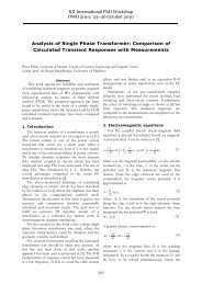
Fig.4. rotor-side and grid-side converters<br />
Fig.5. rotor-side controller<br />
Fig.6. grid-side controller
1.4 Torsional resonance<br />
The rotat<strong>in</strong>g shaft system <strong>in</strong> a w<strong>in</strong>d turb<strong>in</strong>e is<br />
devided <strong>in</strong>to sections. The turb<strong>in</strong>e itself is quite<br />
heavy and the mach<strong>in</strong>e rotor is light. The shaft<br />
connect<strong>in</strong>g the generator and the turb<strong>in</strong>e cannot be<br />
assumed to be <strong>of</strong> <strong>in</strong>f<strong>in</strong>nite stiffness. The gearbox<br />
reducess the stiffness. Therefore the shaft will twist<br />
as it transits torque from one end to other. A simple<br />
method for model<strong>in</strong>g the shaft system <strong>in</strong> matlab is<br />
shown <strong>in</strong> Fig.7.<br />
Fig.7. <strong>Generator</strong> and turb<strong>in</strong>e torque <strong>in</strong>teraction.<br />
Because the mass <strong>of</strong> the shaft itself is very small,<br />
seen from the geneerator, it is reduced to zero.<br />
The <strong>in</strong>ertia at the turb<strong>in</strong>e gives a negative<br />
contribution to the torque when the generator is <strong>in</strong><br />
generatong mode.<br />
Fig.8. <strong>Doubly</strong>-<strong>Fed</strong> <strong>Induction</strong> generator diagram.<br />
381<br />
The torque Tshaft available to be transmitted by the<br />
shaft is:<br />
;<br />
The torque at the generator end seen from the<br />
shaft is:<br />
;<br />
The twist<strong>in</strong>g <strong>of</strong> the shaft depends from the shaft<br />
torsional or the compliance coefficient Kshaft :<br />
; ;<br />
<br />
The <strong>in</strong>ertia constant H, is def<strong>in</strong>ed as:<br />
1<br />
<br />
2 <br />
;<br />
<br />
; ;<br />
1.5 Pitch angle control system<br />
The pitch angle is constant at zero degree until<br />
the speed reaches po<strong>in</strong>t D speed <strong>of</strong> the track<strong>in</strong>g<br />
characteristic. Beyond po<strong>in</strong>t D the pitch angle is<br />
proportional to the speed deviation from po<strong>in</strong>t D<br />
speed.<br />
For electromagnetic transients <strong>in</strong> power systems<br />
the pitch angle control is <strong>of</strong> less <strong>in</strong>terest. The w<strong>in</strong>d<br />
speed should be selected such that the rotational<br />
speed is less then po<strong>in</strong>t D speed.<br />
Fig.9. Rotor – side converter control system diagram.
2. <strong>Simulation</strong> & Results<br />
On the figures above are shown the block<br />
diagrams <strong>of</strong> the <strong>Doubly</strong>-<strong>Fed</strong> <strong>in</strong>duction generator<br />
Fig.8; The rotor-side control system Fig.9 and the<br />
grid-side control system diagram Fig.10;<br />
A 9 MW w<strong>in</strong>d farm consist<strong>in</strong>g <strong>of</strong> six 1.5 MW<br />
w<strong>in</strong>d turb<strong>in</strong>es connected to a 25 kV distribution<br />
system exports power to a 120 kV grid through a 30<br />
km, 25 kV feeder. A 500 kW resistive load and a 0.9<br />
Mvar (Q=50) filter are connected at the 400 V<br />
generation bus. The turb<strong>in</strong>e parameters specify<strong>in</strong>g<br />
rat<strong>in</strong>gs <strong>of</strong> power components <strong>of</strong> the w<strong>in</strong>d turb<strong>in</strong>e are<br />
saved <strong>in</strong> a companion M file:<br />
Pnom=1.5e6/0.9; %Nom<strong>in</strong>al power (VA)<br />
Vnom=400; %L<strong>in</strong>e-L<strong>in</strong>e voltage<br />
(Vrms)<br />
Fnom=50; %Hz<br />
Rs=0.00706; %pu<br />
Lls=0.171; %pu<br />
Rr=0.005; %pu<br />
Llr=0.156; %pu<br />
Lm=2.9; %pu<br />
H=5.04; %Inertia constant (s)<br />
F=0.01; %Friction factor (pu)<br />
p=3; %Number <strong>of</strong> pairs <strong>of</strong><br />
poles<br />
Initially the DFIG w<strong>in</strong>d farm produces 4.8<br />
MW. This active power, corresponds to the<br />
maximum mechanical turb<strong>in</strong>e output for a<br />
10m/s w<strong>in</strong>d speed (0.55*9 MW=4.95 MW)<br />
m<strong>in</strong>us electrical losses <strong>in</strong> generator. The<br />
correspond<strong>in</strong>g turb<strong>in</strong>e speed is 1.09 pu <strong>of</strong><br />
generator synchronous speed. The DC voltage<br />
is regulated at 1200 V and reactive power is<br />
kept at 0 Mvar. At t=0.03 s the positivesequence<br />
voltage suddenly drops to 0.8 p.u.<br />
caus<strong>in</strong>g an oscillation on the DC bus voltage<br />
and on the DFIG output power.<br />
Fig.10. Grid – side converter control system diagram.<br />
382<br />
Dur<strong>in</strong>g the voltage sag the control system<br />
regulates DC voltage and reactive power at<br />
their set po<strong>in</strong>ts (1200 V, 0 Mvar). The system<br />
recovers <strong>in</strong> approximately 4 cycles.<br />
Fig.11. Voltage at the DFIG term<strong>in</strong>als<br />
Fig.12. Active power.<br />
Fig.13. Reactive power
4. Conclusion<br />
Fig.14. DC l<strong>in</strong>k Voltage.<br />
The model<strong>in</strong>g <strong>of</strong> a <strong>Doubly</strong>-<strong>Fed</strong> <strong>in</strong>duction<br />
generator driven by a w<strong>in</strong>d turb<strong>in</strong>e has been<br />
described. The model is a discrete-time version<br />
<strong>of</strong> the W<strong>in</strong>d Turb<strong>in</strong>e <strong>Doubly</strong>-<strong>Fed</strong> <strong>Induction</strong><br />
<strong>Generator</strong> (Phasor type) <strong>of</strong> Matlab&Simul<strong>in</strong>k<br />
Sym-Power systems.<br />
<strong>Simulation</strong> results shown <strong>in</strong> Fig. 11-15<br />
illustrate the system response to a l<strong>in</strong>e-toground<br />
fault.<br />
Fig. 14 shows that the DC bus voltage <strong>of</strong><br />
the w<strong>in</strong>d turb<strong>in</strong>e is strongly affected by the<br />
fault.<br />
This suggests that nearby faults should be<br />
simulated to study their impacts on the w<strong>in</strong>d<br />
farms and on the power systems.<br />
383<br />
3. Bibliography<br />
Fig.15. Turb<strong>in</strong>e speed.<br />
[1] Ion Boldea, “Variable speed generators” (Electric<br />
power eng<strong>in</strong>eer<strong>in</strong>g series). Publ. CRC 2005.<br />
[2] Jack Casazza & nbsp Frank Delea:<br />
“Understand<strong>in</strong>g Electric Power Systems” Publ.:<br />
Wiley-IEEE 2003<br />
[3] Matlab & Simul<strong>in</strong>k v.7.6.0, “W<strong>in</strong>d Turb<strong>in</strong>e<br />
<strong>Doubly</strong>-<strong>Fed</strong> <strong>Induction</strong> <strong>Generator</strong> (Average model)” –<br />
Help files<br />
[4] W<strong>in</strong>d Turb<strong>in</strong>e - Wikipedia<br />
Authors:<br />
M.Sc.Student<br />
Dosijanoski Branislav<br />
Faculty <strong>of</strong> Electrical<br />
Eng<strong>in</strong>eer<strong>in</strong>g and Information<br />
Technologies, University Ss.<br />
Cyril & Methodius, Skopje.<br />
Oil Ref<strong>in</strong>ery “Brilliant” Ltd. Stip<br />
Ma<strong>in</strong>tenance Eng<strong>in</strong>eer<br />
Str. Bregalnicka bb<br />
2000 Stip<br />
tel. +389(32) 391-319<br />
fax. +389(32) 397-420<br />
email: d7branko@Yahoo.com