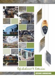
DUBE SQUARE CANOPY
DUBE SQUARE CANOPY
DUBE SQUARE CANOPY

You also want an ePaper? Increase the reach of your titles
YUMPU automatically turns print PDFs into web optimized ePapers that Google loves.
project team<br />
Developer/Owner:<br />
Dube Tradeport<br />
Architect:<br />
CNdV Africa landscape architects<br />
Structural Engineer:<br />
Henry Fagan & Partners<br />
Steelwork Contractor<br />
STS Engineering<br />
Steel detailing company<br />
PSM<br />
24 Steel Construction Vol. 36 No. 2 2012<br />
PROJECTS<br />
For the tendered scheme a central circular node<br />
was proposed orientated at the average of the six<br />
adjoining planes it connected, with solid infill<br />
ends to the gridshell members machined to meet<br />
the external surface of the node. Bolts with<br />
shaped washers would bolt through from the<br />
inside node to threads in the machined pieces.<br />
With the input of the contractor this concept<br />
was changed to a welded proposal eliminating<br />
the need for the solid machined ends and any<br />
pre-drilled holes in the node. The ends of the<br />
rectangular sections were instead cut to the<br />
profile of the outside surface of the node and<br />
directly welded into panels of nodes in the shop.<br />
To accommodate the various orientations of the<br />
adjoining members, the circular node projects<br />
through the roof surface and is capped with a<br />
circular glass plate. Its internal end is either<br />
capped with a solid infill plate or light fitting.<br />
While at times up to 12m above people’s heads<br />
these nodes are in some way brought closer to<br />
the observer by the shadows they cast at their<br />
feet on the square’s surface.<br />
ERECTION<br />
Piling, pile-caps and plinths were first constructed<br />
for all six support locations with cast-in<br />
anchors for the connection of the base of the<br />
rear columns and oversized plinths recessed<br />
below the final landscape level to allow some<br />
tolerance on position of the ground connections<br />
relative to the concrete works.<br />
The rear columns rise 10 metres above the square to meet the gridshell at the<br />
three rear node connections.<br />
The three rear columns were then erected and the perimeter arches installed.<br />
The length of these curved pipes meant site welding was required to achieve an<br />
uninterrupted arc and these were achieved with an internal collar pipe.<br />
Bespoke tower structures were designed and fabricated by STS Engineering with<br />
an adjustable top fixing to provide the flexibility required for temporary support<br />
to the various orientations of the prefabricated node assemblies in their final<br />
position while the adjoining infill members were welded between them and the<br />
adjacent modules. This propping ‘swept’ across the structure as the gridshell<br />
infill completed from the building corner to the outer ground node gained its full<br />
structural integrity.<br />
CONCLUSION<br />
The conception, design and fabrication of this structure took place while a<br />
debate within structural engineering around ‘Just because we can do it doesn’t<br />
mean we should’ has become increasingly vocal.<br />
Why should contemporary capabilities of advanced analysis, geometry<br />
generation and automated fabrication be concentrated on ‘solving problems<br />
that didn’t need to be solved’ on structures and geometries that are perhaps<br />
unnecessarily complex?<br />
The authors believe that in this case such complications and ‘gymnastics’ were<br />
justified due to the nature of the structure as a sculptural centrepiece to the<br />
new city and a catalyst around which the life of its inhabitants will take shape<br />
as they hopefully enjoy the space for everything from simple lunchtime shade to<br />
large gatherings at evening events.<br />
Its form and construction take many cues and influence from the forces acting<br />
on it and these are articulated in both logical structural solutions such as the<br />
large-scale ripple/corrugation of the gridshell surface and the more ‘poetic’<br />
expression of structural actions such as the leaning form of the rear columns.<br />
Both are considered to equally contribute to its success.