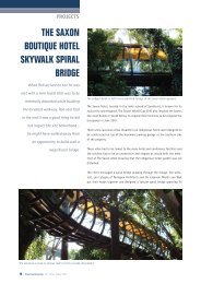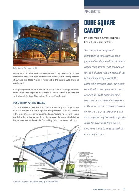
DUBE SQUARE CANOPY
DUBE SQUARE CANOPY
DUBE SQUARE CANOPY

You also want an ePaper? Increase the reach of your titles
YUMPU automatically turns print PDFs into web optimized ePapers that Google loves.
Dube Square Canopy at night.<br />
Dube City is an urban mixed-use development taking advantage of all the<br />
connections and opportunities afforded by its location within walking distance<br />
of Durban’s King Shaka Airport. It forms part of the massive Dube Tradeport<br />
development.<br />
Having designed the infrastructure for the overall scheme, landscape architects<br />
CNdV Africa were requested to conceive a canopy structure to form the<br />
centrepiece of the Dube City’s main public space, Dube Square.<br />
DESCRIPTION OF THE PROJECT<br />
The client wanted a free-form, iconic structure, able to give some protection<br />
from the elements, but with a light and transparent feel. This was developed<br />
with a series of inclined perimeter arches ‘skipping’ around the edge of a rippling<br />
gridshell surface rising towards the middle storeys of the surrounding buildings<br />
but set away from the L-shaped office building under construction to its rear.<br />
A work in progress sketch developing ground node details.<br />
PROJECTS<br />
<strong>DUBE</strong> <strong>SQUARE</strong><br />
<strong>CANOPY</strong><br />
By Mark Mallin, Senior Engineer,<br />
Henry Fagan and Partners<br />
The conception, design and<br />
fabrication of this structure took<br />
place while a debate within structural<br />
engineering around ‘Just because we<br />
can do it doesn’t mean we should’ has<br />
become increasingly vocal. The<br />
authors believe that in this case such<br />
complications and ‘gymnastics’ were<br />
justified due to the nature of the<br />
structure as a sculptural centrepiece<br />
to the new city and a catalyst around<br />
which the life of its inhabitants will<br />
take shape as they hopefully enjoy the<br />
space for everything from simple<br />
lunchtime shade to large gatherings<br />
at evening events.<br />
Steel Construction Volume. 36 No. 2 2012 21
22 Steel Construction Vol. 36 No. 2 2012<br />
PROJECTS<br />
Further development and structural rationalisation<br />
of the form introduced a large-scale ‘ripple’ across<br />
the structure’s surface with the corrugations<br />
amplified to a maximum towards the centre of the<br />
structure where moments within the gridshell are<br />
greatest and fading out towards the perimeter<br />
arches.<br />
The front of the canopy is supported on two full<br />
‘ground to ground’ arches, the largest of which<br />
spans 30m with a rise of approximately 3.8m. The<br />
two sides are supported on ‘ground to top of<br />
column’ arches. The back then consists of two<br />
shallow ‘top of column to top of column’ arches,<br />
spanning 22.5m and 15m respectively.<br />
The roof is made up of a series of triangular panels,<br />
typically of 1.8m sides, joined together to form a<br />
gridshell which undulates to form a complex<br />
surface.<br />
FOUNDATIONS<br />
Much of the site consisted of landfill generated by<br />
the groundworks and levelling for the adjacent<br />
airport project. Piled foundations were therefore<br />
required with the pile groups designed by the<br />
geotechnical engineer to resist the thrusts<br />
generated by the supporting arches of the<br />
gridshell.<br />
The complexity of the gridshell structure is in some<br />
way brought closer to the observer by the shadows<br />
cast at their feet on the square’s surface.<br />
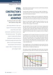
The analysis model of the axial forces, tensions and compressions due to ripple<br />
corrugations.<br />
REAR COLUMNS<br />
The rear columns, extending approximately 1m below ground level, rise a further<br />
10m above the square to meet the gridshell at the three rear node connections.<br />
In elevation the section tapers from 2.1m at their base to 400mm at the top<br />
expressing their ‘stiff’ direction to resist the bending moments resulting from<br />
the cantilevered columns resistance to the thrusts of the gridshell.<br />
The columns lean back a total of 2m from their centre line expressing their<br />
reaction to the thrusts of the gridshell.<br />
However, the columns are only 300mm wide when viewed from the front of the<br />
adjacent building’s elevation to minimise their profile. They therefore provide<br />
little resistance to thrusts in this transverse direction. The whole system relies<br />
on the shell to mobilise its own membrane stiffness.<br />
Originally envisaged as concrete, rolled H-Sections with infill plates were<br />
proposed by the engineer at tender stage for both quality control and speed of<br />
erection while minimising the number of trades involved. For ease of<br />
construction and accuracy the contractor proposed profile cut plate to achieve<br />
a more precise curve in lieu of the curved sections with excellent results.<br />
Horizontal shadow gaps at the joints between the infill plates give further ‘scale’<br />
and interest to the profile while the recess to the web plates allows for a narrow<br />
strip of lighting to continue up the column face reflecting the language of the<br />
landscaping below.<br />
At the top of the columns the gridshell is raised off the column to a pin<br />
connection to achieve a lightness of touch when viewed from acute angles<br />
below.<br />
GROUND NODES<br />
The design team put a lot of time and effort into the appropriate detailing of<br />
ground connections, primarily because this was where the structure is closest to<br />
the ground and therefore most visible and tactile to the public.
As well as sitting at varying levels in hard and soft landscaping, these three<br />
details had to achieve a consistent language to resolve the inclined freeform<br />
geometry of the gridshell to the plane of the ground.<br />
A profile cut splice plate was orientated on the centre line of the plane of<br />
intersection of the two pipe sections with a perpendicular circular plate<br />
resolving the orientation of the projecting fin-plate to be perpendicular to<br />
the ground plane connected through a large diameter pin.<br />
GRIDSHELL MEMBERS<br />
Many European examples for similar structures have been constructed to<br />
fully enclose and weatherproof the internal space while maximising the<br />
outside feel. To achieve this, the depth and especially width of the structural<br />
profile were usually minimised and the bespoke sections fabricated<br />
accordingly.<br />
Since the primary purpose of this canopy was to provide shade, minimising<br />
this section was not such a driving force and at tender stage two alternative<br />
section profiles were proposed; the first using standard rectangular hollow<br />
sections for obvious programme and cost benefits due to their general<br />
availability; the second proposing a tapered profile with the width of the top<br />
wall determined by the minimum bearing required by the glass edges and the<br />
bottom fabricated from a solid bar with the side walls.<br />
PROJECTS<br />
Both were of similar cost, with the reduced weight<br />
of the ‘bespoke’ option being offset by the<br />
increased costs of its fabrication. With the go<br />
ahead for construction the decision was made due<br />
to programme constraints to proceed with<br />
standard rectangular hollow sections and<br />
perimeter pipe. Perimeter pipes were rolled from<br />
273 x 10thk circular hollow sections and the<br />
internal gridshell members from 200mm x 100mm<br />
rectangular hollow sections with either 6mm or<br />
10mm wall thickness.<br />
GRIDSHELL NODE CONNECTIONS<br />
There are 304 internal node connections within the<br />
980m2 of the gridshell surface, all of differing<br />
geometries with a further 81 connections to the<br />
perimeter pipe.<br />
The pros and cons of various options for<br />
connections were considered by the engineer at<br />
the design stage with the ease of site erection of<br />
bolted connections weighed against the machining<br />
and fabrication accuracies that were required.<br />
Steel Construction Volume. 36 No. 1 2012 23
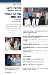
project team<br />
Developer/Owner:<br />
Dube Tradeport<br />
Architect:<br />
CNdV Africa landscape architects<br />
Structural Engineer:<br />
Henry Fagan & Partners<br />
Steelwork Contractor<br />
STS Engineering<br />
Steel detailing company<br />
PSM<br />
24 Steel Construction Vol. 36 No. 2 2012<br />
PROJECTS<br />
For the tendered scheme a central circular node<br />
was proposed orientated at the average of the six<br />
adjoining planes it connected, with solid infill<br />
ends to the gridshell members machined to meet<br />
the external surface of the node. Bolts with<br />
shaped washers would bolt through from the<br />
inside node to threads in the machined pieces.<br />
With the input of the contractor this concept<br />
was changed to a welded proposal eliminating<br />
the need for the solid machined ends and any<br />
pre-drilled holes in the node. The ends of the<br />
rectangular sections were instead cut to the<br />
profile of the outside surface of the node and<br />
directly welded into panels of nodes in the shop.<br />
To accommodate the various orientations of the<br />
adjoining members, the circular node projects<br />
through the roof surface and is capped with a<br />
circular glass plate. Its internal end is either<br />
capped with a solid infill plate or light fitting.<br />
While at times up to 12m above people’s heads<br />
these nodes are in some way brought closer to<br />
the observer by the shadows they cast at their<br />
feet on the square’s surface.<br />
ERECTION<br />
Piling, pile-caps and plinths were first constructed<br />
for all six support locations with cast-in<br />
anchors for the connection of the base of the<br />
rear columns and oversized plinths recessed<br />
below the final landscape level to allow some<br />
tolerance on position of the ground connections<br />
relative to the concrete works.<br />
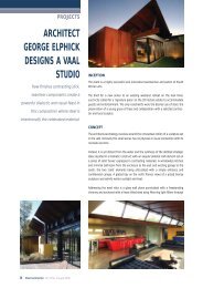
The rear columns rise 10 metres above the square to meet the gridshell at the<br />
three rear node connections.<br />
The three rear columns were then erected and the perimeter arches installed.<br />
The length of these curved pipes meant site welding was required to achieve an<br />
uninterrupted arc and these were achieved with an internal collar pipe.<br />
Bespoke tower structures were designed and fabricated by STS Engineering with<br />
an adjustable top fixing to provide the flexibility required for temporary support<br />
to the various orientations of the prefabricated node assemblies in their final<br />
position while the adjoining infill members were welded between them and the<br />
adjacent modules. This propping ‘swept’ across the structure as the gridshell<br />
infill completed from the building corner to the outer ground node gained its full<br />
structural integrity.<br />
CONCLUSION<br />
The conception, design and fabrication of this structure took place while a<br />
debate within structural engineering around ‘Just because we can do it doesn’t<br />
mean we should’ has become increasingly vocal.<br />
Why should contemporary capabilities of advanced analysis, geometry<br />
generation and automated fabrication be concentrated on ‘solving problems<br />
that didn’t need to be solved’ on structures and geometries that are perhaps<br />
unnecessarily complex?<br />
The authors believe that in this case such complications and ‘gymnastics’ were<br />
justified due to the nature of the structure as a sculptural centrepiece to the<br />
new city and a catalyst around which the life of its inhabitants will take shape<br />
as they hopefully enjoy the space for everything from simple lunchtime shade to<br />
large gatherings at evening events.<br />
Its form and construction take many cues and influence from the forces acting<br />
on it and these are articulated in both logical structural solutions such as the<br />
large-scale ripple/corrugation of the gridshell surface and the more ‘poetic’<br />
expression of structural actions such as the leaning form of the rear columns.<br />
Both are considered to equally contribute to its success.
TASS Engineering has been actively involved in structural and architectural steel fabrication<br />
and erection for more than four decades.<br />
Current projects:<br />
• Standard Bank Rosebank - Standard Bank<br />
• Telesure Head Office - Steyn City Properties<br />
• Medupi Coal & Ash Terrace - ELB<br />
• Medupi Tripper Car & Sishen Tripper Car - Efficient<br />
Engineering<br />
• Heavy Duty Workshop - Efficient Engineering<br />
• Warehouses - Koedoespoort - Transnet<br />
• Warehouse - Pferd<br />
• Nestlé Babelegi<br />
• Heineken Brewery - Heineken<br />
• Road Gantries - SANRAL<br />
• Bus Rapid Transport System - JDA