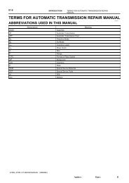
4HP20 REPAIR MANUAL
4HP20 REPAIR MANUAL
4HP20 REPAIR MANUAL

Create successful ePaper yourself
Turn your PDF publications into a flip-book with our unique Google optimized e-Paper software.
Versione99/04/01<br />
CD<br />
<strong>REPAIR</strong> <strong>MANUAL</strong><br />
4<br />
HP-<br />
20<br />
ZF GETRIEBE GMBH SAARBRÜCKEN
subject to alterations<br />
© Copyright 1998 all rights reserved and published by<br />
ZF Getriebe GmbH, Saarbrücken, Department MKTD<br />
No part of this manual may be reproduced or transmitted in any form or<br />
by any means, electronic or mechanical, including photocopying and recording,<br />
for any purpose without the express written permission of<br />
ZF Getriebe GmbH, Saarbrücken<br />
Printed in Germany
Table of contents<br />
Page<br />
Preliminary information ii<br />
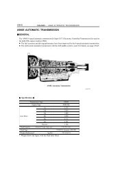
1. General information 1.1/1<br />
1.1 Picture of the transmission 1.1/1<br />
1.2 Power flow diagram 1.2/1<br />
1.3 Specifications 1.3/1<br />
1.3.1 Screw torque specifications 1.3/1<br />
1.3.1.1 Converter bell housing (PSA/RSA) 1.3/1<br />
1.3.1.2 Converter bell housing (MB) 1.3/1<br />
1.3.1.3 Converter bell housing (FIAT) 1.3/1<br />
1.3.1.1 Transmission cover (PSA/RSA) 1.3/1<br />
1.4 Adjustments 1.4/1<br />
1.4.0 Measuring the clutch packs (procedure) 1.4/1<br />
1.4.1 Adjusting the preload for the side shaft and differential 1.4/3<br />
1.4.1.1 Determining side shaft installation space 1.4/3<br />
1.4.1.2 Determining side shaft installation height 1.4/5<br />
1.4.1.3 Determining the side shaft shim 1.4/7<br />
1.4.1.4 Determining differential installation space 1.4/8<br />
1.4.1.5 Determining differential installation height 1.4/10<br />
1.4.1.6 Determining the differential shim 1.4/12<br />
1.4.2 Adjusting the preload for the bearing plate 1.4/13<br />
1.4.3 Adjusting brakes C and D 1.4/18<br />
1.4.3.1 Adjusting clearance of brake D (adjustment disc) 1.4/18<br />
1.4.3.2 Adjusting clearance of clutch C (snap ring) 1.4/19<br />
1.4.4 Adjusting clearance of cylinder C (snap ring) 1.4/21<br />
1.4.5 Adjusting clutches B and E 1.4/22<br />
1.4.5.1 Determining snap ring play 1.4/23<br />
1.4.5.2 Measuring installation space, clutch B 1.4/24<br />
1.4.5.3 Measuring installation space, clutch E 1.4/25<br />
1.4.5.4 Measuring clutch pack B 1.4/26<br />
1.4.5.5 Determining adjustment disc B 1.4/26<br />
1.4.5.6 Measuring clutch pack E 1.4/27<br />
1.4.5.7 Determining adjustment disc E 1.4/27<br />
1.4.6 Installing position switch 1.4/28<br />
1.4.7 Adjusting clearance of brake F 1.4/29<br />
1.4.7.1 Measuring installation space F 1.4/29<br />
1.4.7.2 Measuring clutch pack F 1.4/30<br />
1.4.7.3 Determining adjustment disc F 1.4/30<br />
1.4.8 Assembly cover for adjusting axial play (preparation) 1.4/31<br />
1.4.9 Adjusting axial play, input shaft 1.4/32<br />
1.5 Tightening torques 1.5/1<br />
1.6 Transmission test (test bench) 1.6/1<br />
1.7 Special tools 1.7/1<br />
1.8 Function tests 1.8/1<br />
1.8.1 Position switch 1.8/1<br />
1.8.1.1 PSA/RSA 1.8/1<br />
1.8.1.2 MB/FIAT 1.8/1<br />
99/04/01 4 HP 20 © ZF Getriebe GmbH Saarbrücken CD<br />
I
2. Disassembly 2.1/1<br />
2.1 Removing converter, control unit 2.1/1<br />
2.2 Removing clutch B/E 2.2/1<br />
2.3 Removing and dismantling planetary gear set I + II 2.3/1<br />
2.4 Taking out brake C and D 2.4/1<br />
2.5 Removing shifting mechanism and ancillaries 2.5/1<br />
2.6 Dismantling the converter bell housing 2.6/1<br />
2.7 Dismantling clutch B/E and brake C/D 2.7/1<br />
2.7.1 Dismantling clutch B/E 2.7/1<br />
2.7.2 Dismantling brake C/D 2.7/4<br />
2.8 Dismantling the cover, bearing plate, side shaft and differential 2.8/1<br />
2.8.1 Dismantling the cover 2.8/1<br />
2.8.2 Dismantling the bearing plate 2.8/1<br />
2.8.3 Dismantling the side shaft 2.8/3<br />
2.8.4 Dismantling the differential 2.8/3<br />
3. Assembly 3.1/1<br />
3.1 Completing the differential and side shaft 3.1/1<br />
3.1.1 Completing the differential 3.1/1<br />
3.1.2 Completing the side shaft 3.1/2<br />
3.2 Installing the parking lock mechanism and bearing shells in the housing 3.2/1<br />
3.2.1 Installing the parking lock mechanism in the housing 3.2/1<br />
3.2.2 Installing the bearing shells in the housing 3.2/3<br />
3.3 Completing and installing the bearing plate 3.3/1<br />
3.4 Installing brake C/D, planetary drive and clutch B/E<br />
in the transmission housing 3.4/1<br />
3.4.1 Installation of brake D/C 3.4/2<br />
3.4.1.1 Completing brake D 3.4/2<br />
3.4.1.2 Completing brake C 3.4/3<br />
3.4.2 Installation of planetary drive 3.4/5<br />
3.4.3 Completing clutch B and E 3.4/6<br />
3.4.3.1 Inserting clutch pack E 3.4/8<br />
3.4.3.2 Inserting clutch pack B 3.4/8<br />
3.5 Completing and installing the transmission cover 3.5/1<br />
3.6 Installing brake F 3.6/1<br />
3.7 Installing the side shaft, differential, parking lock and position switch 3.7/1<br />
3.7.1 Installing the side shaft and differential 3.7/1<br />
3.7.2 Installing the parking lock and position switch 3.7/2<br />
3.8 Installing the converter bell housing, control unit, inductive transmitter<br />
and oil pan 3.8/1<br />
3.8.1 Completing and installing the converter bell housing 3.8/1<br />
3.8.2 Installing the control unit, inductive transmitter and oil pan 3.8/8<br />
3.9 Installing ancillaries (oil cooler, converter, speedometer shaft<br />
connection, transport protection cap) 3.9/1<br />
3.9.1 Installing the oil cooler 3.9/2<br />
3.9.2 Installing the breather cover, oil dipstick and oil drain plug 3.9/3<br />
3.9.3 Installing the converter 3.9/3<br />
3.9.4 Installing the speedometer shaft with connection 3.9/3<br />
3.9.5 Function test for the position switch 3.9/3<br />
3.9.6 Installing the protective transport caps 3.9/4<br />
II CD<br />
4 HP 20 © ZF Getriebe GmbH Saarbrücken<br />
99/04/01
Preliminary information<br />
This manual covers the procedure for repairing the complete transmission.<br />
The repairing of this transmission is only allowed to persons with specific training from ZF<br />
Getriebe GmbH.<br />
The entire disassembly and assembly procedure is described in chronological order.<br />
The photographs were kept general in nature so that they can be used with various applications;<br />
they are not binding in every case.<br />
We use Service Bulletins and training to announce important information and<br />
application-specific changes that must be taken into consideration in maintenance work.<br />
If this repair manual is given to a third party, there will be no modification service.<br />
The Service Bulletins regulations and specifications must be followed when making repairs.<br />
Depending on the type of damage that has occured, the repair work can be limited to that which is<br />
necessary to repair the damage.<br />
In this case you must observe the following:<br />
• Seals (such as O-rings, shaft seals, gaskets, and filters) must always renewed.<br />
• All O-rings, rectangular-section rings, and other sealing rings must always be lubricated<br />
with petroleum jelly before installation.<br />
• All bearings must always be oiled lightly when installed.<br />
• For transmissions that have covered a large number of kilometers (> 80,000 km), all lined<br />
clutch discs and steel clutch discs must be replaced.<br />
• After clutches/ brakes have been damaged, the converter, oil tubes, and oil cooler, must be<br />
cleaned thoroughly with a suitable cleaning agent.<br />
• If brakes C or D has been damaged, or if a considerable distance has been covered (><br />
80,000 km), pistons C and D must be replaced.<br />
The following requirements should be met before the repair work is started:<br />
• The required special tools should be available.<br />
(The complete set of special tools is listed in Chapter 1.7)<br />
• A suitable transmission testing rig should be available.<br />
The required testing values can be found in the Service Bulletins.<br />
99/04/01 4 HP 20 © ZF Getriebe GmbH Saarbrücken CD<br />
III
Note:<br />
This manual treats the automatic control unit as a complete unit, which should not be disassembled<br />
without special knowledge; it should be exchanged as a complete unit.<br />
A separate repair manual is planned for the automatic control unit.<br />
Important:<br />
The transmission is filled with long-life oil.<br />
The oil does not have to be changed until it has been in use for ten years.<br />
The transmission must only be delivered with the oil type and oil amount specified in the corresponding<br />
parts list documentation (see Part List).<br />
Technical After Sales Service Technical Documentation After Sales Service School<br />
Bach Reus Schultz<br />
IV CD<br />
4 HP 20 © ZF Getriebe GmbH Saarbrücken<br />
99/04/01
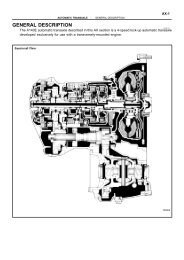
1. General information<br />
1.1 Picture of the transmission<br />
99/04/01 4 HP 20 © ZF Getriebe GmbH Saarbrücken CD<br />
1.1/1
1.2 Power flow diagram<br />
1st GEAR<br />
Input<br />
3rd GEAR<br />
Input<br />
Reverse<br />
GEAR<br />
Input<br />
Output<br />
Output<br />
Output<br />
99/04/01<br />
Output<br />
Output<br />
Output<br />
Input<br />
Input<br />
4 HP 20 © ZF Getriebe GmbH Saarbrücken<br />
2nd GEAR<br />
4th GEAR<br />
Output Output<br />
Output<br />
CD<br />
Output<br />
1.2/1
99/04/01<br />
4 HP 20 © ZF Getriebe GmbH Saarbrücken<br />
1.3 Specifications<br />
1.3.1 Screw torque specifications<br />
1.3.1.1Converter bell housing (PSA)<br />
First pre-tighten the screws in the following<br />
order:<br />
19 ➮ 14 ➮ 9 ➮ 8 ➮ 3 ➮ 4<br />
Then, in numerical order, tighten the<br />
screws all the way (see diagram).<br />
1 ➮ 2 ➮ 3 ➮ ...➮23<br />
Important!<br />
The numbers correspond to the actual<br />
sequence for final tightening.<br />
(Assessment, Specification 1019700137)<br />
(See Chapter 1.5 for tightening torque)<br />
1.3.1.2 Converter bell housing (MB)<br />
First pre-tighten the screws in the following<br />
order:<br />
21 ➮ 20 ➮ 11 ➮ 8 ➮ 3 ➮ 4<br />
Then, in numerical order, tighten the<br />
screws all the way (see diagram).<br />
1 ➮ 2 ➮ 3 ➮ ...➮24<br />
Important!<br />
The numbers correspond to the actual<br />
sequence for final tightening<br />
(Assessment, Specification 1019 700 138 )<br />
(See Chapter 1.5 for tightening torque)<br />
1.3.1.3 Converter bell housing (FIAT)<br />
First pre-tighten the screws in the following<br />
order.<br />
19 ➮ 20 ➮ 11 ➮ 8 ➮ 3 ➮ 6<br />
Then, in numerical order, tighten the<br />
screws all the way (see diagram).<br />
1 ➮ 2 ➮ 3 ➮ ...➮24<br />
Important!<br />
The numbers correspond to the actual<br />
sequence for final tightening<br />
(Assessment, Specification 1019700088)<br />
(See Chapter 1.5 for tightening torque)<br />
CD<br />
1.3/1
1.3.1.4Transmission cover (PSA/RSA)<br />
First pre-tighten the screws in the following<br />
order.<br />
4 ➮ 5<br />
Then, in numerical order, tighten the<br />
screws all the way (see diagram).<br />
1 ➮ 2 ➮ 3 ➮ ... ➮ 5<br />
Important!<br />
The numbers correspond to the actual<br />
sequence for final tightening<br />
(Assessment, Specification 1019 700 218)<br />
(See Chapter 1.5 for tightening torque)<br />
1.3/2 CD<br />
4 HP 20 © ZF Getriebe GmbH Saarbrücken<br />
99/04/01
98009<br />
98011<br />
98012<br />
99/04/01 4 HP 20 © ZF Getriebe GmbH Saarbrücken CD<br />
1.4 Making adjustments<br />
1.4.0 Measuring the clutch packs<br />
(procedure)<br />
Place the two intermediate pieces<br />
5p01 050 329/5p01 060 329 on the<br />
marked position on measuring fixture<br />
5p01 000 330.<br />
Using the knurled screw, turn adjusting<br />
device 5p01 001 458 to the upper limit.<br />
Attach force measuring unit<br />
5p01 000 329 to adjusting device.<br />
Fasten it with 4 knurled screws to the<br />
measuring fixture using the intermediate<br />
pieces.<br />
Using a fixing pin, connect measuring<br />
plate 5p01 040 330 with the force measuring<br />
unit.<br />
Using the knurled screw, clamp the<br />
clutch pack to be measured (with steel<br />
disc on the top and corrugated disc – if<br />
there is one – on the bottom) in the<br />
device at 200N.<br />
1.4/1
Check the value on the force measuring<br />
unit’s display.<br />
Then place measuring bar 5p01 060 330<br />
on the measuring plate, put the the dial<br />
gauge’s measuring base in the measuring<br />
plate’s groove on the top disc of the set,<br />
and set the dial gauge to 0.<br />
Now use the measuring bar to measure<br />
down to the base plate.<br />
Read the measurement value ➮ M X<br />
Note!<br />
In each case, the X index in M X stands<br />
for the brake/ clutch clutch packs that are<br />
put in (B, C, D, E, F).<br />
1.4/2<br />
CD<br />
4 HP 20 © ZF Getriebe GmbH Saarbrücken<br />
98017<br />
98018<br />
99/04/01
98104<br />
97577<br />
99/04/01 4 HP 20 © ZF Getriebe GmbH Saarbrücken CD<br />
1.4.1 Adjusting the preload for the<br />
side shaft and differential<br />
1.4.1.1Determining side shaft installation space<br />
Insert plug gauge 5p89 004 178 into the<br />
side shaft bearing seat on the transmission<br />
housing and use the measuring bar<br />
to measure down to the plug gauge from<br />
the transmission housing support surface.<br />
Installation space B SG is equal to the<br />
G SG value plus plug gauge height H SG .<br />
Calculation:<br />
B SG = G SG + H SG<br />
Insert plug gauge 5p89 004 177 into the<br />
side shaft bearing seat on the converter<br />
bell housing and use the measuring bar to<br />
measure down to the plug gauge from the<br />
converter bell support surface.<br />
Installation space B SW is equal to the<br />
G SW value plus plug gauge height H SW .<br />
Calculation:<br />
B SW = G SW + H SW<br />
Installation space for the side shaft B S is<br />
now determined from installation space<br />
B SG plus installation space B SW plus<br />
constant K P for the paper gasket.<br />
Calculation:<br />
B S = B SG + B SW + K P<br />
1.4/3
Example (for 1.4.1.1):<br />
HSG = 82.492 mm<br />
HSW = 34.497 mm<br />
KP = 0.26 mm<br />
G SG = 0.215 mm<br />
G SW = 0.55 mm<br />
B SG = 0.215 + 82.492<br />
= 82.707 mm<br />
B SW = 0.55 + 34.497<br />
= 35.047 mm<br />
➮ B S = 82.707 + 35.047 + 0.26<br />
= 118.014 mm<br />
1.4/4 CD<br />
4 HP 20 © ZF Getriebe GmbH Saarbrücken<br />
99/04/01
98120<br />
98121<br />
98123<br />
99/04/01 4 HP 20 © ZF Getriebe GmbH Saarbrücken CD<br />
1.4.1.2 Determining side shaft<br />
installation height<br />
Fix bush 5p01 120 331 in basic tool for<br />
height measuring device 5p01 000 331<br />
with 3 screws (M6x16) and in measuring<br />
plate 5p01 040 331 bush 5p01 110 331<br />
with 4 screws (M6x12). Insert outer bearing<br />
shell in bush 5p01 120 331. Insert the<br />
side shaft into the basic tool of heightmeasuring<br />
fixture 5p01 000 331. Fasten<br />
measuring plate 5p01 040 331 onto the<br />
basic tool with eight screws (M10x30).<br />
Important!<br />
Strictly cleanliness !<br />
(See Chapter 1.5 for tightening torques)<br />
Put outer bearing shell on side shaft and<br />
measuring bell 5p01 130 331 on the<br />
bearing outer ring.<br />
Set intermediate pieces 5p01 000 329 on<br />
the positions marked on the measuring<br />
plate.<br />
Use the knurled screw to turn adjusting<br />
device 5p01 001 458 to the upper limit.<br />
Hang force measuring unit 5p01 000 329<br />
in adjusting device 5p01 001 458 and<br />
screw it together with the height-measuring<br />
fixture using the intermediate pieces.<br />
Connect the measuring bell to the force<br />
measuring unit using a fixing pin.<br />
Use the knurled screw to clamp the side<br />
shaft into the device at 300 N.<br />
Check the value on the force measuring<br />
unit’s display.<br />
Turn the side shaft for several complete<br />
turns.<br />
Using the measuring bar, measure the<br />
excess height from the measuring bell<br />
tongues to the measuring plate.<br />
1.4/5
To do this, place the measuring bar on<br />
the measuring bell’s tongue, set to 0, and<br />
then measure down to the measuring<br />
plate. Do the measurement procedure on<br />
both tongues.<br />
Average the M 1 , M 2 measurement values<br />
➮ M S<br />
The height of the side shaft H S is equal<br />
to the averaged measurement value M S<br />
plus the constant dimension for the<br />
height measurement device K S minus the<br />
constant dimension for the thrust bell K G .<br />
Calculation:<br />
H S = K S + M S - K G<br />
Example: (for 1.4.1.2)<br />
KS KG M1 M2 M S<br />
H S<br />
= 132.287 mm<br />
= 30.013 mm<br />
= 14.33 mm<br />
= 14.27 mm<br />
= (14.33 + 14.27)/2<br />
= 14.3 mm<br />
= 132.287 + 14.3 - 30.013<br />
= 116.574<br />
1.4/6<br />
CD<br />
4 HP 20 © ZF Getriebe GmbH Saarbrücken<br />
98124<br />
99/04/01
99/04/01 4 HP 20 © ZF Getriebe GmbH Saarbrücken CD<br />
1.4.1.3 Determining the side shaft<br />
shim<br />
Zero dimension N S is equal to installation<br />
space B S minus side shaft height H S.<br />
Disc thickness S S is equal to zero dimension<br />
N S plus preload dimension V S – in accordance<br />
with specification 0000 700 907.<br />
The parts list shows preload dimension V S as<br />
0.07 to 0.12 mm. The test value is permissible<br />
when it is between 0.055 and 0.135 mm.<br />
Calculation:<br />
N S = B S - H S<br />
S S = V S + N S<br />
Example: (for 1.4.1.3)<br />
BS HS V S<br />
N S<br />
S S<br />
= 118.014 mm<br />
= 116.574 mm<br />
= 0.07 to 0.12 mm<br />
= 118.014 - 116.574<br />
= 1.44 mm<br />
= 1.44 + (0.07 bis 0.12)<br />
= 1.51 to 1.56 mm<br />
Chosen:<br />
➮ S S = 1.54 mm<br />
1.4/7
1.4.1.4 Determining differential<br />
installation space<br />
Insert plug gauge 5p89 004 681 into<br />
bearing seat for differential transmission<br />
housing and use measuring bar to measure<br />
down from transmission housing support<br />
surface to the plug gauge.<br />
Installation space B DG is equal to measured<br />
G DG dimension plus plug-gauge height H DG .<br />
Calculation:<br />
B DG = G DG + H DG<br />
Important!<br />
Use plug gauge 5p89 004 768 for MB<br />
application.<br />
Insert plug gauge 5p89 004 682 into the<br />
bearing seat for the differential converter<br />
bell housing and, using the measuring<br />
bar, measure down to the plug gauge bell<br />
from the converter bell housing support<br />
surface.<br />
Installation space B DW is equal to the<br />
measured G DW dimension plus the plug<br />
gauge height H DW .<br />
Calculation:<br />
B DW = G DW + H DW<br />
Installation space for the differential B D<br />
is now determined from installation<br />
space B DG plus installation space B DW<br />
plus the constant K P for the paper gasket.<br />
Calculation:<br />
B D = B DG + B DW + K P<br />
1.4/8 CD<br />
4 HP 20 © ZF Getriebe GmbH Saarbrücken<br />
99/04/01
99/04/01 4 HP 20 © ZF Getriebe GmbH Saarbrücken CD<br />
Example (for 1.4.1.4):<br />
HDG = 24.996 mm<br />
HDW = 119.998 mm<br />
KP = 0.26 mm<br />
G DG = 0.285 mm<br />
G DW = 0.67 mm<br />
B DG = 0.285 + 24.996<br />
= 25.281 mm<br />
B DW = 0.67 + 119.998<br />
= 120.668 mm<br />
➮ B D = 25.281 + 120.668 + 0.26<br />
= 146.209 mm<br />
1.4/9
1.4.1.5 Determining the differential<br />
installation height<br />
Fix bush 5p01 060 331 into basic tool for<br />
height measuring device 5p01 000 331<br />
with 3 screws (M6x16).Insert outer bearing<br />
shell in bush 5p01 060 331<br />
Insert the differential into the basic tool<br />
of height-measuring fixture<br />
Fasten measuring plate 5p01 040 331 onto<br />
the basic tool with eight screws (M10x30).<br />
Important!<br />
Strictly cleanliness !<br />
Bush 5p01 050 331 is to be fixed with<br />
4 screws (M6x12) into measuring plate<br />
5p01 040 331 for MB application.<br />
(See Chapter 1.5 for tightening torques)<br />
Set outer bearing shell on differential and<br />
measuring bell 5p01 070 331 onto bearing<br />
outer ring.<br />
Put the intermediate pieces 5p01 000 329<br />
on the positions marked on the measuring<br />
plate.<br />
Using the knurled screw, turn the adjusting<br />
device to the upper limit.<br />
Hang force measuring unit 5p01 000 329<br />
in adjusting device 5p01 001 458 and<br />
screw it together with the height-measuring<br />
fixture using the intermediate pieces.<br />
Connect the measuring bell with the<br />
force measuring unit using a fixing pin.<br />
Using the knurled screw, clamp the<br />
differential into fixture at 300 N.<br />
Check the value on the force measuring<br />
unit.<br />
Give the differential several complete<br />
turns.<br />
Using the measuring bar, measure the<br />
excess height from the measuring bell<br />
tongues to the measuring plate.<br />
1.4/10<br />
CD<br />
4 HP 20 © ZF Getriebe GmbH Saarbrücken<br />
98125<br />
98126<br />
98123<br />
99/04/01
98127<br />
99/04/01 4 HP 20 © ZF Getriebe GmbH Saarbrücken CD<br />
To do this, place the measuring bar on<br />
the measuring bell’s tongue, set to 0, and<br />
then measure down to the measuring<br />
plate. Do the measurement procedure on<br />
both tongues.<br />
Average the M 3 , M 4 measurement values<br />
➮ M D<br />
The height of the differential H D is equal<br />
to the averaged measurement value M D<br />
plus the constant dimension for the<br />
height measurement device K D minus the<br />
constant dimension for the trust bell K G<br />
Calculation:<br />
H D = K S + M D - K G<br />
Example: (for 1.4.1.5)<br />
KD KG M3 M4 M D<br />
H S<br />
= 151.242 mm<br />
= 30.013 mm<br />
= 23.35 mm<br />
= 23.51 mm<br />
= (23.35 + 23.51)/2<br />
= 23.43mm<br />
= 151.242 + 23.43 - 30.013<br />
= 144.659 mm<br />
1.4/11
1.4.1.6 Determining the differential<br />
shim<br />
Zero dimension N D is equal to installation<br />
space B D minus differential height H D .<br />
Disc thickness S D is equal to zero dimension<br />
N D plus preload dimension V D – acc.<br />
to specification 0000 700 907.<br />
The preload dimension V D from the parts<br />
list is 0.21 to 0.26 mm. Permissible test<br />
value is 0.195 to 0.275 mm.<br />
Calculation:<br />
N D = B D - H D<br />
S D = V D + N D<br />
Example: (for 1.4.1.3)<br />
BD HD V D<br />
N D<br />
S D<br />
= 146.209 mm<br />
= 144.659 mm<br />
= 0.21 bis 0.26 mm<br />
= 146.209 -144.659<br />
= 1.55 mm<br />
= 1.55 + (0.21 bis 0.26)<br />
= 1.76 bis 1.81 mm<br />
Selected:<br />
➮ S D = 1.78 mm<br />
1.4/12 CD<br />
4 HP 20 © ZF Getriebe GmbH Saarbrücken<br />
99/04/01
97583<br />
97585<br />
97587<br />
99/04/01 4 HP 20 © ZF Getriebe GmbH Saarbrücken CD<br />
1.4.2 Adjusting the preload for the<br />
bearing plate<br />
In order to ensure play, measuring ring<br />
5x46 041 752 is used for Completing the<br />
bearing plate (Chapter 3.3) during<br />
adjustment instead of an adjusting ring.<br />
The bearing plate is put into the housing<br />
and fastened with six screws.<br />
Insert the side shaft. Install the bolt, support<br />
bolt, and parking lock pawl with leg<br />
spring.<br />
Attach the spring.<br />
Engage the parking lock.<br />
Remove the slotted nut with securing ring.<br />
Screw measuring nut 5x46 032 123 on<br />
and tighten it.<br />
Release the parking lock.<br />
(See Chapter 1.5 for tightening torques)<br />
1.4/13
Fasten spacer sleeve 5x46 022 123 onto<br />
the bearing plate with three screws.<br />
Mount measuring plate 5x46 012 123 on<br />
spacer sleeve with five machine screws.<br />
On top of this, fasten adjusting device<br />
5p01 001 458 with four knurled screws<br />
so that the bores of .screw measuring nut<br />
and adjusting device fit.<br />
(See Chapter 1.5 for tightening torques)<br />
Attach measuring nut with bolt to adjusting<br />
device.<br />
Tighten knurled screw until resistance is<br />
felt, then turn a half further rotation.<br />
Turn the output gear further with the side<br />
shaft until the indicator on the dial settles<br />
down, and set the dial gauge to 0.<br />
Now turn the knurled screw in the opposite<br />
direction until resistance can be<br />
detected, and give it a half further rotation.<br />
Turn the output gear further by turning<br />
the side shaft until the indicator on the<br />
dial gauge settles down and then read the<br />
dial gauge ➮ dimension M<br />
Note !<br />
Turn until the indicator movements no<br />
longer become smaller.<br />
1.4/14<br />
CD<br />
4 HP 20 © ZF Getriebe GmbH Saarbrücken<br />
97588<br />
97589<br />
97590<br />
99/04/01
Example: (for 1.4.2)<br />
99/04/01 4 HP 20 © ZF Getriebe GmbH Saarbrücken CD<br />
Zero dimension N is equal to the thickness<br />
of disc D minus dimension M.<br />
Calculation:<br />
N = D - M<br />
Shim thickness S is equal to zero dimension<br />
N minus adjusting dimension V, preload<br />
dimension V acc. to specification<br />
0000 700 907, from the parts list is 0.03<br />
to 0.085 mm.<br />
The test value is permissible if it is between<br />
0.03 and 0.1 mm<br />
Remove measuring fixture.<br />
Calculation:<br />
S = N - V<br />
M = 0.22 mm<br />
D = 6.3 mm<br />
V = 0.03 to 0.085 mm<br />
N = 6.3 - 0.22 mm<br />
= 6.08 mm<br />
S = 6.08 - (0.03 to 0.085)<br />
S = 5.995 to 6.05 mm<br />
Selected:<br />
➮ S = 6.025 mm<br />
1.4/15
Remove adjusting device, bearing plate<br />
and spacer saver, engage the parking lock<br />
and loosen the measuring nut.<br />
Release the parking lock and remove the<br />
bolt, supporting bolt, parking lock pawl,<br />
leg spring, and side shaft.<br />
Take the bearing plate back off and replace<br />
the installed shim with the one<br />
determined.<br />
Note !<br />
See<br />
Dismantling the bearing plate (Chapter 2.8.2)/<br />
Completing the bearing plate (Chapter 3.3)<br />
1.4/16 CD<br />
4 HP 20 © ZF Getriebe GmbH Saarbrücken<br />
99/04/01
98112<br />
98114<br />
99/04/01 4 HP 20 © ZF Getriebe GmbH Saarbrücken CD<br />
1.4.3 Adjusting brakes C and D<br />
1.4.3.1Adjusting clearance of brake D<br />
(adjustment disc)<br />
Determine brake D installation space E D<br />
with measuring bar 5p01 060 330.<br />
To do this set measuring bar on the edge<br />
of the brake D disc carrier. Put measuring<br />
base on highest point of disc supporting<br />
surface on ridge and set the dial<br />
gauge to 0.<br />
Pull the measuring sensor upwards, insert<br />
it into the snap ring groove and press it<br />
against the groove’s upper edge.<br />
Read off measured value on dial gauge ➮ W D<br />
Determine thickness M D of clutch pack<br />
for brake D (without adjustment disc)<br />
according to Chapter 1.4.0: Measuring<br />
the clutch packs.<br />
➮ M D<br />
Installation space E D is equal to measured<br />
value W D plus base thickness F ➮ E D .<br />
Test value P D is then derived from installation<br />
space E D minus M D .<br />
Value P D must lie between 4.46 and 5.73<br />
mm. Test specification 1019 700 108<br />
Use test dimension P D to select adjustment<br />
disc L D .<br />
Calculation:<br />
E D = W D + F + S D<br />
P D = E D - M D<br />
1.4/17
Example (for 1.4.3.1):<br />
F = 1.48 mm (base thickness)<br />
WD = 17.02mm<br />
MD = 13.43 mm<br />
E D<br />
P D<br />
= 17.02 + 1.48<br />
= 18.5 mm<br />
= 18.5 - 13.43<br />
= 5.07 mm<br />
From the table:<br />
➮ L D =2.1 mm<br />
1.4/18 CD<br />
4 HP 20 © ZF Getriebe GmbH Saarbrücken<br />
99/04/01
98113<br />
98115<br />
99/04/01 4 HP 20 © ZF Getriebe GmbH Saarbrücken CD<br />
1.4.3.2Adjusting clearance of clutch C<br />
(snap ring)<br />
Determine installation space E C for brake<br />
C with measuring bar 5p01 060 330.<br />
For this, set measuring bar on the edge of<br />
the brake C disc carrier. Place the measuring<br />
base on the highest point on the<br />
disc support surface on the ridge and set<br />
the dial gauge to 0.<br />
Pull the measuring sensor upwards, insert<br />
it into the snap ring groove and press it<br />
against the groove’s upper edge.<br />
Read off measured value on the dial ➮ W C<br />
Determine thickness M C of the clutch<br />
pack for brake C (without cup spring)<br />
according to Chapter 1.4.0: Measuring<br />
the clutch packs.<br />
➮ M C<br />
Installation space E C is equal to measured<br />
value W C plus base thickness F ➮ E C<br />
Test value P C is then equal to installation<br />
space E C minus M C .<br />
According to test specification 1019 700 085,<br />
value P C must lie between 1.86 and 2.4<br />
mm. According to test specification<br />
1019 700 216, it must lie between 1.77<br />
and 2.28 mm (brake disc release).<br />
1.4/19
Select snap ring S C using test dimension<br />
P C .<br />
Calculation:<br />
E C = W C + F<br />
P C = E C - M C<br />
Example (for 1.4.3.2):<br />
F = 1.48 mm (base thickness)<br />
WC = 6.95 mm<br />
MC = 6.41 mm<br />
E C<br />
P C<br />
= 6.95 + 1.48<br />
= 8.43 mm<br />
= 8.43 - 6.41<br />
= 2.02 mm<br />
From the table:<br />
➮ S C =1.5 mm<br />
1.4/20 CD<br />
4 HP 20 © ZF Getriebe GmbH Saarbrücken<br />
99/04/01
98102<br />
99/04/01 4 HP 20 © ZF Getriebe GmbH Saarbrücken CD<br />
1.4.4 Adjusting clearance of<br />
cylinder C (snap ring)<br />
Put measuring fixture 5p01 002 925 on<br />
cylinder C.<br />
Press the measuring base down on the<br />
top edge of the cylinder and set the dial<br />
gauge to 0.<br />
Release the measuring base and swivel it<br />
into the snap ring groove so that it<br />
touches the upper edge of the groove.<br />
Repeat measurement twice, turning by<br />
120°.<br />
Average measurement values M 1, M 2,<br />
M 3 ➮ M. Adding D to M then gives you<br />
test dimension P.<br />
Test dimension P should lie between 3.10<br />
and 3.90 mm. Specification 1019 700 201<br />
Use test dimension P to select snap ring S.<br />
Release play should be between 0.05 and<br />
0.25 mm. (200 N)<br />
Calculation:<br />
P = M + D<br />
Example (for 1.4.4):<br />
D = 1.48 mm<br />
M1 M2 M3 = 1.93 mm<br />
= 1.88 mm<br />
= 1.83 mm<br />
M = (1.93 +1.88 + 1.83) / 3<br />
= 1.88 mm<br />
P = 1.88 + 1.48<br />
= 3.36 mm<br />
➮ S = 3.2 mm<br />
1.4/21
1.4.5 Adjusting clutches B and E.<br />
Insert the clutch E adjusting ring on piston<br />
E and secure with snap ring<br />
02.010/230.<br />
(Here variant B)<br />
Note !<br />
Adjusting ring E<br />
for variant A 5p89 004 182<br />
for variant B 5p89 004 374<br />
Specification 1019 700 126<br />
Put the clutch B adjusting ring on the<br />
snap ring.<br />
Insert cup 02.090 and secure it with snap<br />
ring 02.100.<br />
(Here variant B)<br />
Note !<br />
Adjusting ring B<br />
for variant A 5p89 004 181<br />
for variant B 5p89 005 403<br />
Specification 1019 700 127<br />
Put the complete set on measuring fixture<br />
5p01 002 984 and connect the fixture<br />
to the compressed-air system.<br />
Note !<br />
Maximum air pressure: 5 bar.<br />
1.4/22<br />
CD<br />
4 HP 20 © ZF Getriebe GmbH Saarbrücken<br />
97615<br />
97616<br />
97617<br />
99/04/01
97618<br />
97619<br />
99/04/01 4 HP 20 © ZF Getriebe GmbH Saarbrücken CD<br />
1.4.5.1 Determining snap ring play<br />
Put the dial gauge sensor on the clutch B<br />
adjusting ring.<br />
Feed compressed air to clutch B via control<br />
valve.<br />
Set dial gauge to 0.<br />
After this, pressurize clutch E via the<br />
control valve and read measurement<br />
value.<br />
Repeat measurement twice with th set<br />
turned by 120°.<br />
Average measuremenmt values M 1, M 2,<br />
M 3 ➮ snap ring play S<br />
S = (M 1 + M 2 + M 3) / 3<br />
Example (for 1.4.5.1):<br />
M1 M2 M3 = 0.27 mm<br />
= 0.23 mm<br />
= 0.25 mm<br />
➮ S = (0.27 + 0.23 + 0.25) / 3<br />
= 0.25 mm<br />
1.4/23
1.4.5.2 Measuring installation space,<br />
clutch B<br />
Put the dial gauge’s sensor on the clutch<br />
B adjusting ring.<br />
Feed compressed air to clutch E via control<br />
valve. Set dial gauge to 0.<br />
Lift measurement ring B by hand until it<br />
touches the cup and read the measurement<br />
value.<br />
Repeat measurement twice with the set<br />
turned by 120°. ➮ M 4, M 5, M 6<br />
Average measurement values M 4, M 5,<br />
M 6 ➮ M B<br />
The minimum installation space E B is<br />
equal to the height of the ring R B plus<br />
measurement value M B<br />
Calculation:<br />
M B = (M 4 + M 5 + M 6) / 3<br />
E B = R B + M B<br />
Example (for 1.4.5.2):<br />
M4 M5 M6 RB M B<br />
= 2.36 mm<br />
= 2.40 mm<br />
= 2.38 mm<br />
= 11.99 mm<br />
= (2.36 + 2.40 + 2.38) / 3<br />
= 2.38 mm<br />
➮ E B = 11.99 + 2.38<br />
= 14.37 mm<br />
1.4/24<br />
CD<br />
4 HP 20 © ZF Getriebe GmbH Saarbrücken<br />
97620<br />
99/04/01
97621<br />
99/04/01 4 HP 20 © ZF Getriebe GmbH Saarbrücken CD<br />
1.4.5.3 Measuring installation space,<br />
clutch E<br />
Put the dial gauge’s sensor on the clutch<br />
E adjusting ring.<br />
Set dial gauge to 0.<br />
Feed compressed air to clutch E via control<br />
valve, and read off the measured value.<br />
Repeat procedure twice with the set<br />
turned by 120°. ➮ M 7 , M 8,M 9<br />
Average measurement values M 7 , M 8,<br />
M 9. ➮ M E<br />
Now take the adjusting rings off again.<br />
The minimum installation space E E<br />
equals ring height R E plus M E minus<br />
snap ring play S.<br />
Calculation:<br />
M E = (M 7 + M 8 + M 9)/3<br />
E E =R E + M E - S<br />
Example (for 1.4.5.3):<br />
M7 M8 M9 RE M E<br />
=2.6 mm<br />
= 2.55 mm<br />
= 2.54 mm<br />
= 20,98 mm<br />
= (2.6 + 2.55 + 2.54) / 3<br />
= 2.56 mm<br />
➮ E E = 20.98 + 2.56 - 0.25<br />
= 23.29 mm<br />
1.4/25
1.4.5.4 Measuring clutch pack B<br />
Determine thickness M B for the clutch<br />
pack for clutch B (without adjustment<br />
disc) according to Chapter 1.4.0:<br />
Measuring the clutch packs.<br />
➮ M B<br />
1.4.5.5Determining adjustment disc B.<br />
Test dimension P B is equal to the installation<br />
space E B minus set thickness M B.<br />
Determine adjustment disc E B from<br />
specification 1019 700 127<br />
For variant B, test dimension P B should<br />
lie between 2.56 and 3.86 mm.<br />
Calculation:<br />
P B = E B - M B ➮ L B<br />
Using test dimension P B , select adjustment<br />
disc L B .<br />
Example (for 1.4.5.4/1.4.5.5):<br />
MB EB P B<br />
= 11.44 mm<br />
= 14.38 mm<br />
= 14.38 - 11.44<br />
= 2.94 mm<br />
➮ L B =2.1 mm<br />
1.4/26<br />
CD<br />
4 HP 20 © ZF Getriebe GmbH Saarbrücken<br />
98116<br />
99/04/01
98117<br />
99/04/01 4 HP 20 © ZF Getriebe GmbH Saarbrücken CD<br />
1.4.5.6 Measuring clutch pack E<br />
Determine thickness M E for the clutch<br />
pack for clutch E (without adjustment<br />
disc) according to Chapter 1.4.0:<br />
Measuring the clutch packs.<br />
➮ M E<br />
1.4.5.7 Determining adjustment disc E<br />
Test dimension P E is equal to installation<br />
space E E minus set thickness M E.<br />
For variant B, test dimension P E should<br />
lie between 5.33 and 6.66 mm.<br />
Determine adjustment disc E E from<br />
specification 1019 700 126<br />
Calculation:<br />
P E = E E - M E ➮ L E<br />
Use test dimension P E to select adjustment<br />
disc L E<br />
Example (for 1.4.5.7):<br />
ME EE P E<br />
= 16.78 mm<br />
= 23.29 mm<br />
= 23.29 - 16.78<br />
= 6.51 mm<br />
➮ L E = 4.8 mm<br />
1.4/27
1.4.6 Installing position switch<br />
Loosen screws 01.180 for adjusting plate<br />
01.150 so that the adjusting plate slides<br />
easily.<br />
Slide adjustment tool 5x46 001 454 into<br />
transmission position N on the selector<br />
shaft so that the dowel pin of the adjustment<br />
tool fits into the bore in the adjusting<br />
plate.<br />
Clamp the adjustment tool tightly<br />
Tighten the screws.<br />
(Torx TX-27H)<br />
(See Chapter 1.5 for tightening torque)<br />
Check the adjustment by removing the<br />
adjustment tool, switching through all<br />
positions twice, and then putting the<br />
adjustment tool in the N position back<br />
on.<br />
If the dowel does not fit into the adjusting<br />
plate, repeat the adjustment.<br />
After this affix the screw heads with<br />
safety coating.<br />
1.4/28<br />
CD<br />
4 HP 20 © ZF Getriebe GmbH Saarbrücken<br />
97641<br />
97642<br />
99/04/01
97655<br />
99/04/01 4 HP 20 © ZF Getriebe GmbH Saarbrücken CD<br />
1.4.7 Adjusting clearance of brake F<br />
1.4.7.1 Measuring installation space F<br />
Using a depth gauge, measure from the<br />
transmission housing sealing surfaces to<br />
the piston’s disc support surface at two<br />
opposing points ➮ M 1,M 2<br />
Average the measurement values M 1,M 2<br />
➮ B F<br />
Calculation:<br />
B F =(M 1 + M 2) / 2<br />
Example (for 1.4.7.1):<br />
M1 M2 B F<br />
= 18.6 mm<br />
= 18.8 mm<br />
= (18.6 + 18.8) / 2<br />
= 18.7 mm<br />
1.4/29
1.4.7.2 Measuring clutch pack F<br />
Determine thickness M F of the clutch F<br />
clutch pack (without adjustment disc)<br />
according to Chapter 1.4.0: Measuring<br />
the clutch packs.<br />
➮ M F<br />
1.4.7.3 Determining adjustment disc F<br />
Test dimension P F is equal to installation<br />
space B F minus set thickness D F.<br />
Determine adjustment disc E F from<br />
specification 1019 700 084<br />
Test dimension P F should lie between<br />
3.79 and 4.93 mm.<br />
Calculation:<br />
P F = B F - M F ➮ E F<br />
Use test dimension P F to select adjustment<br />
disc E F.<br />
Example (for 1.4.7.2/1.4.7.3):<br />
MF BF P F<br />
= 14.2 mm<br />
= 18.7 mm<br />
= 18.7 - 14.2<br />
=4.5 mm<br />
➮ E F =3.3 mm<br />
1.4/30<br />
CD<br />
4 HP 20 © ZF Getriebe GmbH Saarbrücken<br />
98118<br />
99/04/01
97632<br />
97633<br />
97634<br />
99/04/01 4 HP 20 © ZF Getriebe GmbH Saarbrücken CD<br />
1.4.8 Assembly cover for adjusting<br />
axial play (preparation)<br />
Put oil feeding bush 01.020/120 without<br />
sealing sleeves 01.020/140 on transmission<br />
cover 01.020/110 and secure with<br />
snap ring 01.020/160.<br />
Place shim 01.100 and bearing 01.090 on<br />
cylinder B/E.<br />
Note!<br />
The selected shim should allow axial<br />
play.<br />
Put the transmission cover on the housing<br />
and screw the cover on tight with four<br />
Torx screws 01.064 and 1 Torx screw<br />
01.060.<br />
Important!<br />
See tightening torque specifications in<br />
Chapter 1.3<br />
1.4/31
1.4.9 Adjusting axial play, input shaft<br />
Clamp fixture 5p01 002 379 on the input<br />
shaft so that the measuring base rests on<br />
the stator shaft.<br />
Set dial guage to 0.<br />
Determine axial play by pulling and pressing<br />
on the handle (repeat measurement).<br />
Average the measurement values M 1, M 2 ➮ M<br />
Remove the measuring fixture.<br />
Play S should be (according to specification<br />
1019 700 222) between 0.18 and 0.42 mm.<br />
Example (for 1.4.9):<br />
M1 = 0.51 mm<br />
M2 = 0.49 mm<br />
M = (0.51 + 0.49)/2<br />
=0.5 mm<br />
S = 0.18 to 0.42 mm<br />
D = 0.5 -(0.18 to 0.42)<br />
= 0.08 to 0.32 mm<br />
➮ D = 0.2 mm (selected)<br />
Disc thickness must be between 0.08 and<br />
0.32 mm thicker. It is sensible to select<br />
one with a disc that averages 0.2 mm<br />
thicker than the one that was installed.<br />
1.4/32<br />
CD<br />
4 HP 20 © ZF Getriebe GmbH Saarbrücken<br />
97659<br />
97660<br />
99/04/01
97633<br />
99/04/01 4 HP 20 © ZF Getriebe GmbH Saarbrücken CD<br />
If the play lies outside the adjustment<br />
range, the shim must be replaced accordingly.<br />
To do this, turn the transmission by 180°<br />
and remove the transmission cover.<br />
Remove the bearing.<br />
Replace the shim with one of appropriate<br />
size and put the bearing back in.<br />
Note!<br />
See Completing and installing transmission<br />
cover (Chapter 3.5)<br />
1.4/33
1.5 Tightening torques<br />
No. Designation Part List- Wrench size Page Tightening<br />
Item-No. No. torque [Nm]<br />
1 Machine screw 22.120 Hexagonal 1.3/1<br />
(pretightening, conv. 22.130 SAF = 13 mm 3.8/5 15 ± 2<br />
bell housing)<br />
(final tightening, “ ) 22.120 26 ± 2.6<br />
22.130<br />
22.132<br />
2 Machine screw 22.134 TORX - TX 40 1.3/1<br />
(final tightening, conv. or 3.8/5 26 ± 2.6<br />
bell housing) Hexagonal<br />
SAF = 13 mm<br />
3 Machine screw 01.060 TORX - TX 40 1.3/2<br />
(pretightening, trans. cover) 01.164 1.4/31 15 ± 2<br />
3.5/2<br />
(final tightening, “ ) 23 ± 2.3<br />
4 Machine screw 09.120 Hexagonal 3.1/1<br />
(differential) SAF = 19 mm 145 ± 14.5<br />
5 Machine screw 06.160 TORX - TX 27 3.2/2<br />
(guide plate) 10 ± 1<br />
6 Machine screw 14.020 TORX - E10 1.4/14<br />
(bearing plate) 3.3/2 35 ± 3.5<br />
7 Slotted nut 14.010/170 Socket wrench 1.4/13<br />
(bearing plate) 5X46 001 089 3.3/2 250 ± 25<br />
8 Machine screw 01.064 TORX - TX 40 3.5/2<br />
(transmission cover) 23 ± 2.3<br />
9 Countersunk screw 01.060 TORX - TX 40 3.5/2<br />
(transmission cover) 23 ± 2.3<br />
10 Machine screw 01.180 TORX - TX 27 H 1.4/28<br />
(adjusting plate, switch ) 10 ± 1<br />
11 Machine screw 01.016 TORX - TX 27 3.7/1<br />
(oil baffle plate) 8 ± 0.8<br />
12 Hexagon screw 01.210 Hexagonal 3.7/2<br />
(switch) SAF = 10 mm 10 ± 1<br />
13 Machine screw 22.230 TORX - TX 27 3.8/2<br />
(oil baffle plate) 8 ± 0.8<br />
99/04/01 4 HP 20 © ZF Getriebe GmbH Saarbrücken CD<br />
1.5/1
No. Designation Part List- Wrench size Page Tightening<br />
Item-No. No. torque [Nm]<br />
14 Machine screw 10.020 TORX - TX 27 3.8/3<br />
(converter bell housing/pump) 10 ± 1<br />
15 Machine screw 10.010/150 TORX - TX 27 3.8/3<br />
(converter bell housing/pump) 10 ± 1<br />
16 Hexagon screw 22.270 Hexagonal 3.8/4<br />
(oil tank) SAF = 10 mm 10 ± 1<br />
17 Hexagon screw 22.180 Hexagonal 3.8/4<br />
(oil filter) SAF = 10 mm 10 ± 1<br />
18 Hexagon screw 22.130 Hexagonal 3.8/5<br />
(converter bell housing/retaining strap) SAF = 13 mm 26 ± 2.6<br />
19 Machine screw 22.132 TORX - TX 40 3.8/5<br />
(converter bell housing) 26 ± 2.6<br />
20 Hexagon screw 22.134 3.8/5<br />
(converter bell housing) 22.120 SAF = 13 mm 26 ± 2.6<br />
21 Union screw 01.290 Hexagonal 3.8/5<br />
(oil tube) SAF = 13 mm 25 ± 2.5<br />
22 Machine screw 01.286 Hexagonal 3.8/6<br />
(oil tube) SAF = 13 mm 23 ± 2.3<br />
23 Screw plug, M10x1 01.260 Internal hexagon 3.8/6<br />
(transmission housing/cover) SAF = 5 mm 20 ± 2<br />
24 Machine screw 01.130 TORX - TX 27 3.8/7<br />
(inductive transmitter) 8 ± 0.8<br />
25 Machine screw 27.300 TORX - TX 27 3.8/8<br />
(control unit) 8 ± 0.8<br />
26 Machine screw 27.230 TORX - TX 27 3.8/8<br />
(inductive transmitter) 8 ± 0.8<br />
27 Hexagon screw 03.050 3.8/8<br />
(oil pan) SAF = 10 mm 6 ± 0.6<br />
28 Screw plug, M12x1,5 01.020/150 Internal hexagon 3.8/8<br />
(transission housing/cover) SAF = 6 mm 20 ± 2<br />
1.5/2 CD<br />
4 HP 20 © ZF Getriebe GmbH Saarbrücken<br />
99/04/01
No. Designation Part List- Wrench size Page Tightening<br />
Item-No. No. torque [Nm]<br />
29 Screw plug, M10x1 22.150 Internal hexagon 3.8/8<br />
(converter bell housing) SAF = 5 mm 12 ± 1.2<br />
30 Union screw 01.340 Internal hexagon 3.9/2<br />
(heat exchanger) SAF = 8 mm 35 ± 3.5<br />
31 Screw plug, M16x1.5 22.100 Internal hexagon 3.9/2<br />
(converter bell housing) SAF = 8 mm 20 ± 2<br />
32 Screw plug, M12x1.5 22.200 Internal hexagon 3.9/2<br />
(converter bell housing) SAF = 6 mm 30 ± 3<br />
33 Hexagon screw 09.392 3.9/3<br />
(speedometer connection) SAF = 11 mm 7 ± 0.7<br />
34 Hexagon screw (M8x55) 3.9/3<br />
(converter retaining bracket) SAF = 13 mm 20 ± 2<br />
35 Hexagon screw (M10x15) 3.9/3<br />
(converter retaining bracket) SAF = 17 mm 20 ± 2<br />
36 Screw (M6x12) Internal hexagon 1.4/5<br />
(height measuring device) SAF = 5 mm 1.4/10 10 ± 1<br />
37 Screw (M6x16) Internal hexagon 1.4/5<br />
(height measuring device) SAF = 5 mm 1.4/10 10 ± 1<br />
38 Screw (M10x30) Internal hexagon 1.4/5<br />
(height measuring device) SAF = 8 mm 1.4/10 35 ± 3,5<br />
99/04/01 4 HP 20 © ZF Getriebe GmbH Saarbrücken CD<br />
1.5/3
1.6 Transmission test (test bench)<br />
The following points must be checked:<br />
Correct oil level<br />
Proper oil level; observe the vehicle manufacturer’s specifications and Part List.<br />
Oil level too low<br />
This can result in:<br />
– Engine over-revving or no power flow in curves or when starting from a stop<br />
– Valve chatter due to air pockets in the oil<br />
– General malfunctions<br />
Among other things, burned clutches can be the result.<br />
Oil level too high<br />
Danger of loss due to splashing, formation of foam, strong increases in temperature at high<br />
road speeds. Loss of oil via breather; among other things, burned clutches and shifting<br />
problems can result.<br />
Proper engine settings<br />
Correct idle speed; follow specifications from vehicle manufacturer.<br />
Power flow, forward and reverse<br />
Correct adjustment of selector linkage or control cable; observe the vehicle manufacturer’s<br />
specifications.<br />
99/04/01 4 HP 20 © ZF Getriebe GmbH Saarbrücken CD<br />
1.6/1
1.7 Special tools<br />
98008<br />
98034<br />
98128<br />
OBJECT Order-No. / Application<br />
Remarks<br />
1<br />
2<br />
3<br />
5p01 000 329<br />
-Force measuring unit<br />
5p01 000 330<br />
-Measuring fixture, clutch play<br />
(Measuring plate:<br />
- short neck >20 mm<br />
- long neck
Identical<br />
Remarks<br />
4 HP 18 Q<br />
5 HP 24<br />
1.7/2<br />
Order-No. / Application OBJECT<br />
5p01 001 458<br />
-Adjusting device, preload<br />
5p01 002 379<br />
-Fixture, axial play, input shaft<br />
5p01 002 925<br />
-Measuring fixture, snap ring play,<br />
cylinder C<br />
CD<br />
4 HP 20 © ZF Getriebe GmbH Saarbrücken<br />
4<br />
5<br />
6<br />
97301<br />
98129<br />
98103<br />
99/04/01
98130<br />
98107<br />
98106<br />
OBJECT Order-No. / Application<br />
Remarks<br />
7<br />
8<br />
9<br />
5p01 002 984<br />
-Measuring fixture, installation<br />
space and snap ring play, clutches<br />
B/E<br />
5p89 004 177<br />
-Plug gauge installation space,<br />
converter bell housing, side shaft<br />
5p89 004 178<br />
-Plug gauge, installation space,<br />
transmission housing, side shaft<br />
99/04/01 4 HP 20 © ZF Getriebe GmbH Saarbrücken CD<br />
1.7/3
Remarks<br />
1.7/4<br />
Order-No. / Application OBJECT<br />
5p89 004 181<br />
-Adjusting ring, clutch B,<br />
variant A (~ 17 mm)<br />
5p89 004 182<br />
-Adjusting ring, clutch E,<br />
variant A (~ 24 mm)<br />
5p89 004 374<br />
-Adjusting ring, clutch E,<br />
variant B (~ 21 mm)<br />
CD<br />
10<br />
11<br />
12<br />
4 HP 20 © ZF Getriebe GmbH Saarbrücken<br />
98131<br />
98132<br />
98133<br />
99/04/01
98134<br />
98305<br />
98135<br />
OBJECT Order-No. / Application<br />
Remarks<br />
13<br />
14<br />
15<br />
5p89 005 403<br />
-Adjusting ring, clutch B,<br />
variant B (~ 12 mm)<br />
5x46 030 167<br />
-Assembly bracket for pressing<br />
down cup spring B<br />
(equivalent to part 3 of device<br />
5x46 000 167)<br />
5x46 000 306<br />
-Plug gauge, pump (moves easily)<br />
Identical<br />
4 HP 14 Q<br />
4 HP 18 Q<br />
4 HP 22<br />
5 HP 18<br />
5 HP 24<br />
Identical<br />
4 HP 18 Q<br />
99/04/01 4 HP 20 © ZF Getriebe GmbH Saarbrücken CD<br />
1.7/5
Identical<br />
Remarks<br />
5 HP 18<br />
5 HP 24<br />
5 HP 30<br />
1.7/6<br />
Order-No. / Application OBJECT<br />
5x46 000 763<br />
-Work bench fixing device<br />
5x46 001 036<br />
-Assembly bracket for pressing<br />
down the cup spring E<br />
5x46 001 046<br />
-Assembly bracket for pressing<br />
down cup spring, brake C/D<br />
CD<br />
16<br />
17<br />
18<br />
4 HP 20 © ZF Getriebe GmbH Saarbrücken<br />
91199<br />
98137<br />
98163<br />
99/04/01
98138<br />
98142<br />
98139<br />
OBJECT Order-No. / Application<br />
Remarks<br />
19<br />
20<br />
21<br />
5x46 001 089<br />
-Slotted nut insert, bearing plate<br />
5x46 001 134<br />
-Assembly drift, shaft seal, selector<br />
shaft<br />
5x46 001 396<br />
-Assembly bracket, transmission,<br />
complete<br />
99/04/01 4 HP 20 © ZF Getriebe GmbH Saarbrücken CD<br />
1.7/7
Remarks<br />
1.7/8<br />
Order-No. / Application OBJECT<br />
5x46 001 418<br />
-Assembly sleeve, retaining ring,<br />
input shaft<br />
5x46 001 443<br />
-Assembly fixture, piston D<br />
5x46 001 453<br />
-Assembly drift, shaft seal, pump<br />
CD<br />
22<br />
23<br />
24<br />
4 HP 20 © ZF Getriebe GmbH Saarbrücken<br />
98143<br />
98144<br />
98140<br />
99/04/01
98141<br />
98145<br />
98146<br />
OBJECT Order-No. / Application<br />
Remarks<br />
25<br />
26<br />
27<br />
5x46 001 454<br />
-Adjusting tool, position switch<br />
5x46 001 775<br />
-Assembly fixture (lifting) for<br />
input shaft with clutches B and E<br />
5x46 002 123<br />
-Adjusting device, preload, bearing<br />
plate<br />
Consisting of:<br />
5x46 012 123 measuring plate<br />
5x46 022 123 spacer sleeve<br />
5x46 032 123 measuring nut<br />
5x46 042 123 measuring ring<br />
99/04/01 4 HP 20 © ZF Getriebe GmbH Saarbrücken CD<br />
1.7/9
Remarks<br />
1.7/10<br />
Order-No. / Application OBJECT<br />
5x46 001 937<br />
-Dismantling tool for pistons B<br />
and E (compressed air)<br />
(tool corresponds to oil feeding<br />
bush 1019 201 069/072 + 3 three<br />
sealing sleeves 0734 401 130)<br />
5x46 001 955<br />
-Core insert for ROLLEX extractor<br />
(side shaft)<br />
5x46 001 956<br />
-Core insert for ROLLEX extractor<br />
(differential)<br />
CD<br />
28<br />
29<br />
30<br />
4 HP 20 © ZF Getriebe GmbH Saarbrücken<br />
98147<br />
98171<br />
98168<br />
99/04/01
98170<br />
98172<br />
98148<br />
OBJECT Order-No. / Application<br />
Remarks<br />
31<br />
32<br />
33<br />
5x46 001 957<br />
-Core insert for ROLLEX extractor<br />
(output spur gear)<br />
5x46 001 999<br />
-Core insert for ROLLEX extractor<br />
(side shaft)<br />
5x46 002 033<br />
-Drift dowl pin<br />
(selector shaft)<br />
99/04/01 4 HP 20 © ZF Getriebe GmbH Saarbrücken CD<br />
1.7/11
Identical<br />
Remarks<br />
3 HP 22<br />
4 HP 14 Q<br />
4 HP 18 Q<br />
4 HP 22<br />
5 HP 18<br />
5 HP 24<br />
5 HP 30<br />
Identical<br />
4 HP 14 Q<br />
4 HP 18 Q<br />
Identical<br />
4 HP 14 Q<br />
4 HP 18 Q<br />
1.7/12<br />
Order-No. / Application OBJECT<br />
5x56 000 090<br />
-Extracting handles for converter<br />
(2 items)<br />
5x46 021 007<br />
Kukko extractor 21/7<br />
or<br />
5x46 021 007<br />
Kukko extractor 21/8<br />
5x46 022 002<br />
Kukko extractor 22-2<br />
(basic tool)<br />
CD<br />
34<br />
35<br />
36<br />
4 HP 20 © ZF Getriebe GmbH Saarbrücken<br />
76046<br />
98149<br />
98150<br />
99/04/01
98151<br />
98152<br />
98153<br />
OBJECT Order-No. / Application<br />
Remarks<br />
37<br />
38<br />
39<br />
5x46 503 491<br />
Rollex extractor Size IA<br />
(basic tool)<br />
5x46 010 011<br />
Rollex extractor 1000/1<br />
(basic tool)<br />
5x46 013 011<br />
Rollex extractor 13000/1<br />
(spur gear, bearing plate)<br />
Identical<br />
4 HP 18 Q<br />
Identical<br />
3 HP 22<br />
4 HP 14 Q<br />
4 HP 18 Q<br />
99/04/01 4 HP 20 © ZF Getriebe GmbH Saarbrücken CD<br />
1.7/13
Identical<br />
Remarks<br />
4 HP 14 Q<br />
4 HP 18 Q<br />
1.7/14<br />
Order-No. / Application OBJECT<br />
5x46 485 001<br />
Rollex extractor 48500<br />
(side shaft)<br />
5x46 302 206<br />
Rollex extractor 30-32206/1<br />
(side shaft)<br />
5x46 032 010<br />
Rollex extractor 32010X/1<br />
(differential)<br />
CD<br />
40<br />
41<br />
42<br />
4 HP 20 © ZF Getriebe GmbH Saarbrücken<br />
98154<br />
98164<br />
98155<br />
99/04/01
98156<br />
OBJECT Order-No. / Application<br />
Remarks<br />
43<br />
5x95 000 415<br />
-Extractor handles, sealing sleeve<br />
99/04/01 4 HP 20 © ZF Getriebe GmbH Saarbrücken CD<br />
1.7/15
Remarks<br />
PSA only<br />
PSA only<br />
PSA only<br />
1.7/16<br />
Order-No. / Application OBJECT<br />
5p89 004 681<br />
-Plug gauge, installation space,<br />
transmission housing, differential<br />
5p89 004 682<br />
-Plug gauge, installation space,<br />
converter bell housing, differential<br />
5x46 001 051<br />
-Fixture for dismantling/ assembly,<br />
cup spring, brake F<br />
CD<br />
44<br />
45<br />
46<br />
4 HP 20 © ZF Getriebe GmbH Saarbrücken<br />
98108<br />
98109<br />
98157<br />
99/04/01
98158<br />
98159<br />
OBJECT Order-No. / Application<br />
Remarks<br />
47<br />
48<br />
5x46 001 450<br />
-Drift, shaft seal, transmission<br />
housing, differential<br />
5x46 001 451<br />
-Drift, shaft seal, converter bell<br />
housing, differential<br />
PSA only<br />
PSA only<br />
99/04/01 4 HP 20 © ZF Getriebe GmbH Saarbrücken CD<br />
1.7/17
MB only<br />
MB only<br />
MB only<br />
Remarks<br />
1.7/18<br />
Order-No. / Application OBJECT<br />
5p89 004 767<br />
-Plug gauge, installation space,<br />
converter bell housing differential<br />
5p89 004 768<br />
-Plug gauge, installation space,<br />
transmission housing, differential<br />
5x46 001 308<br />
-Fixture for disassembly/ assembly,<br />
cup spring, brake F<br />
CD<br />
49<br />
50<br />
51<br />
4 HP 20 © ZF Getriebe GmbH Saarbrücken<br />
98110<br />
98111<br />
98160<br />
99/04/01
98161<br />
98162<br />
98169<br />
OBJECT Order-No. / Application<br />
Remarks<br />
52<br />
53<br />
54<br />
5x46 001 625<br />
-Drift, shaft seal, transmission<br />
housing, differential<br />
5x46 001 627<br />
-Drift, shaft seal, converter bell<br />
housing, differential<br />
5x46 002 000<br />
-Core insert for ROLLEX extractor<br />
(differential)<br />
MB only<br />
MB only<br />
MB only<br />
99/04/01 4 HP 20 © ZF Getriebe GmbH Saarbrücken CD<br />
1.7/19
12<br />
99/04/01<br />
4 HP 20 © ZF Getriebe GmbH Saarbrücken<br />
1.8 Function tests<br />
1.8.1 Position switch<br />
1.8.1.1PSA/RSA<br />
Using a multimeter, make a resistance<br />
test on the switch according to the function<br />
table.<br />
Code table<br />
1.8.1.2MB/FIAT<br />
Using a multimeter, make a resistance<br />
test on the switch according to the function<br />
table.<br />
Code table<br />
CD<br />
1.8/1
97501<br />
97503<br />
97504<br />
99/04/01 4 HP 20 © ZF Getriebe GmbH Saarbrücken CD<br />
2. Disassembly<br />
2.1 Removing converter, control unit<br />
Clamp the transmission into retaining<br />
bracket 5x46 001 396 and fasten onto the<br />
assembly trolley, possibly in work bench<br />
fixing device 5x46 000 763.<br />
Turn the transmission with oil pan<br />
upwards.<br />
Unscrew two oil drain plugs and let the<br />
oil drain.<br />
(Wrench size = Internal hexagon, 8 mm<br />
Wrench size = Internal hexagon, 6 mm)<br />
Remove converter retaining bracket with<br />
fastening screws.<br />
(Wrench size = 17 mm<br />
Wrench size = 13 mm)<br />
Using the converter extracting handles<br />
5x56 000 090, lift the converter out.<br />
2.1/1
Remove the transport plugs from the oil<br />
cooler and selector shaft.<br />
Take out the oil dipstick., if there is one.<br />
Loosen the screws and take off the oil<br />
pan. Remove the seal from the oil pan.<br />
(Wrench size = 10 mm)<br />
Unscrew the screws (large head) on the<br />
control unit, screw off the holder for the<br />
inductive transmitter, and tilt the control<br />
unit.<br />
(Torx TX-27)<br />
2.1/2<br />
CD<br />
4 HP 20 © ZF Getriebe GmbH Saarbrücken<br />
97505<br />
97506<br />
97507<br />
99/04/01
97508<br />
97509<br />
99/04/01 4 HP 20 © ZF Getriebe GmbH Saarbrücken CD<br />
Loosen the fastening screw for the inductive<br />
transmitter under the control unit.<br />
Then lever the cable out of the retaining<br />
clip and pull out the inductive transmitter.<br />
Separate the retaining clip from the plug,<br />
press the plug into the transmission<br />
housing, and remove the complete control<br />
unit.<br />
Then remove the cable clips.<br />
2.1/3
97510<br />
97511<br />
97512<br />
99/04/01 4 HP 20 © ZF Getriebe GmbH Saarbrücken CD<br />
2.2 Removing clutch B/E<br />
Pull out sealing sleeves (brake C) with<br />
extracting tool 5x95 000 415.<br />
Turn transmission by 90°.<br />
Unscrew the oil tube and remove the<br />
retaining plate, screws and oil tube.<br />
Take the O-ring and sealing rings off the<br />
oil tube.<br />
(Wrench size = 19 mm<br />
Wrench size = 13 mm)<br />
Unscrew the two plugs from the cover<br />
and remove the screw plug from the<br />
transmission housing.<br />
Loosen the five Torx screws on the cover<br />
and remove the cover.<br />
(Wrench size = Internal hexagon, 6 mm<br />
Wrench size = Internal hexagon, 5 mm)<br />
(Wrench size = Torx TX-40)<br />
2.2/1
Remove the two sealing rings (clutch<br />
B/E).<br />
Take out input shaft with clutch B/E<br />
using device 5x46 001 775.<br />
Take needle roller bearing and shim out<br />
of clutch B/E.<br />
Remove needle roller bearing and thrust<br />
washer.<br />
2.2/2 CD<br />
4 HP 20 © ZF Getriebe GmbH Saarbrücken<br />
99/04/01
97516<br />
99/04/01 4 HP 20 © ZF Getriebe GmbH Saarbrücken CD<br />
Remove sun wheel with inner disc carrier<br />
B/C.<br />
2.2/3
97517<br />
97518<br />
98101<br />
99/04/01 4 HP 20 © ZF Getriebe GmbH Saarbrücken CD<br />
2.3 Removing and dismantling<br />
planetary gear set I + II<br />
Remove snap ring from ring gear I, and<br />
take out planetary gear set II.<br />
Remove the axial needle roller bearing.<br />
Take out planetary gear set I with ring<br />
gear II, sun wheel I and oil trays.<br />
Take oil trays and sun wheel I off the<br />
planetary gear set.<br />
Take out ring gear I.<br />
Remove snap ring from sun wheel I.<br />
2.3/1
97519<br />
97520<br />
97521<br />
99/04/01 4 HP 20 © ZF Getriebe GmbH Saarbrücken CD<br />
2.4 Taking out brake C and D<br />
Take snap ring out of transmission<br />
housing and remove cylinder with<br />
piston C.<br />
Take disc carrier C/D with clutch packs<br />
and spring clutch disc off piston D.<br />
Release piston D (by applying compressed<br />
air to the feed bore) and remove<br />
it.<br />
Turn transmission by 180°.<br />
2.4/1
Loosen the converter bell housing<br />
screws, and remove the retaining strap<br />
and converter bell housing.<br />
Lift off paper and metal gaskets.<br />
(Wrench size = 13 mm)<br />
(Wrench size = Torx TX-40)<br />
Take off the clutch pack and the brake F<br />
inner disc carrier.<br />
Release the slotted nut lock, mount fixture<br />
5x46 001 051 and remove the brake<br />
F split stop ring.<br />
Remove the fixture and take off the cup<br />
spring.<br />
Important!<br />
Other applications may require a different<br />
assembly fixture.<br />
2.4/2<br />
CD<br />
4 HP 20 © ZF Getriebe GmbH Saarbrücken<br />
97522<br />
97523<br />
97524<br />
99/04/01
97525<br />
97526<br />
97527<br />
99/04/01 4 HP 20 © ZF Getriebe GmbH Saarbrücken CD<br />
Move selector lever to the “N” position.<br />
Remove the position switch screws and<br />
take off the position switch.<br />
(Wrench size = 10 mm)<br />
Loosen the two union screws on the oil<br />
cooler and take off the oil cooler.<br />
(Wrench size = Internal hexagon, 8 mm)<br />
Important!<br />
Take note of the oil cooler seals.<br />
Set the parking lock so that the slotted<br />
nut is held steady and can be removed.<br />
To do this, use the selector shaft to move<br />
to position P.<br />
Loosen the slotted nut with slotted nut<br />
wrench 5x46 001 089.<br />
Release the parking lock.<br />
2.4/3
Take off the parking lock mechanism’s<br />
bolt, pawl, leg spring and support bolt.<br />
Unscrew and remove the guide plate.<br />
(Wrench size = Torx TX-27)<br />
Lift out the differential.<br />
Tilt and remove the side shaft.<br />
Unscrew and remove the oil tray.<br />
(Wrench size = Torx TX-27)<br />
2.4/4<br />
CD<br />
4 HP 20 © ZF Getriebe GmbH Saarbrücken<br />
97528<br />
97529<br />
97530<br />
99/04/01
97531<br />
99/04/01 4 HP 20 © ZF Getriebe GmbH Saarbrücken CD<br />
Release and remove piston F by applying<br />
compressed air to the bore.<br />
Take the two O-rings off piston F.<br />
Remove bearing plate with spur gear.<br />
(Wrench size = Torx - E10)<br />
Important!<br />
Since the bearing seat is tight, press the<br />
bearing plate upwards from underneath<br />
to remove it.<br />
2.4/5
97532<br />
97533<br />
97534<br />
99/04/01 4 HP 20 © ZF Getriebe GmbH Saarbrücken CD<br />
2.5 Removing shifting mechanism<br />
and ancillaries<br />
Turn the transmission by 90°.<br />
Drive out slotted pin.<br />
Take out selector shaft and detent disc<br />
with locking cams and disassemble into<br />
the individual parts.<br />
Then remove the stop bush and sealing<br />
ring.<br />
Use a screwdriver to remove the breather<br />
cover and unscrew the rest of the plugs.<br />
Drive out the differential shaft seal.<br />
(Wrench size = Internal hexagon, 5 mm)<br />
Turn the by transmission 90° and remove<br />
the two bearing shells with the Kukko<br />
extractor. Remove the bearing shim.<br />
(Kukko extractor 5x46 021 007 or<br />
5x46 021 008 combined with basic tool<br />
5x46 022 002).<br />
Note!<br />
The two centering bushes, the position<br />
switch adjusting plate and the breather<br />
normally remain installed.<br />
2.5/1
97535<br />
97536<br />
97537<br />
99/04/01 4 HP 20 © ZF Getriebe GmbH Saarbrücken CD<br />
2.6 Dismantling the converter bell<br />
housing<br />
Take off the oil filter by loosening the<br />
retaining screw.<br />
Pull off the O-ring.<br />
Unscrew the oil tank.<br />
(Wrench size = 10 mm)<br />
Unscrew and remove the oil tray. Pull off<br />
the magnets.<br />
(Wrench size = Torx TX-27)<br />
Take off the protective cap and hexagon<br />
screw for the speedometer connection.<br />
Then remove the speedometer pinion<br />
shaft and connection.<br />
(Wrench size = 11 mm)<br />
2.6/1
Loosen the stator shaft screws and take<br />
out the stator shaft by tapping it slightly<br />
with a plastic hammer.<br />
(Wrench size = Torx TX-27)<br />
Take out the pump wheel and ring gear.<br />
Then unscrew and press out the pump<br />
housing.<br />
Pull off the O-ring, and remove the<br />
centering sleeve.<br />
Lever out the shaft seal pump and<br />
remove the guide ring.<br />
Drive out the differential shaft seal.<br />
Remove the bearing shells with Kukko<br />
extractor.<br />
(Kukko extractor 5x46 021 007 or<br />
5x46 021 008 combined with basic tool<br />
5x46 022 002)<br />
Important!<br />
To prevent possible running noises later,<br />
keep the bearing shells together with the<br />
correct taper roller bearing.<br />
2.6/2<br />
CD<br />
4 HP 20 © ZF Getriebe GmbH Saarbrücken<br />
97538<br />
97539<br />
97540<br />
99/04/01
97541<br />
99/04/01 4 HP 20 © ZF Getriebe GmbH Saarbrücken CD<br />
Unscrew the screw plug from the converter<br />
bell housing.<br />
(Wrench size = Internal hexagon, 5 mm)<br />
2.6/3
97542<br />
97543<br />
97544<br />
99/04/01 4 HP 20 © ZF Getriebe GmbH Saarbrücken CD<br />
2.7 Dismantling clutch B/E, and<br />
brake C/D<br />
2.7.1 Dismantling clutch B/E<br />
Take out the retaining ring and remove<br />
the cup.<br />
Remove clutch pack B.<br />
Remove the rectangular-section ring for<br />
the input shaft and the retaining ring.<br />
2.7/1
Remove inner disc carrier E and axial<br />
needle roller bearing.<br />
Take out the snap ring.<br />
Remove clutch pack E.<br />
Press down cup spring (clutch E) with<br />
assembly fixture 5x46 001 036 and<br />
remove split stop ring.<br />
Remove the oil dam and cup spring.<br />
Pull the O-ring off the oil dam.<br />
2.7/2<br />
CD<br />
4 HP 20 © ZF Getriebe GmbH Saarbrücken<br />
97545<br />
97546<br />
97548<br />
99/04/01
97549<br />
97550<br />
97551<br />
99/04/01 4 HP 20 © ZF Getriebe GmbH Saarbrücken CD<br />
Press down cup spring (clutch B) with<br />
assembly fixture 5x46 030 167 and<br />
remove the split stop ring.<br />
Take out the cup spring.<br />
Put disassembly tool 5x46 001 937 in<br />
cylinder B/E.<br />
Blow out pistons B and E with compressed<br />
air.<br />
Pull out disassembly tool.<br />
Take oil dam off piston B and remove O-ring.<br />
Remove the two O-rings from cylinder B.<br />
Take one O-ring off piston E and one off<br />
cylinder E.<br />
2.7/3
2.7.2 Dismantling brake C/D<br />
Press piston C out of cylinder C.<br />
Hold down cup spring (brake C) with<br />
assembly fixture 5x46 001 046 and<br />
remove snap ring.<br />
Then take out the final disc, cup spring,<br />
and clutch pack.<br />
Turn over disc carrier C/D and remove<br />
snap ring (brake D) with assembly fixture<br />
5x46 001 046 by pressing down the<br />
cup spring.<br />
Then remove the clutch pack and cup<br />
spring.<br />
Note !<br />
If the fitting keys are not loose, leave<br />
them on the disc carrier.<br />
2.7/4<br />
CD<br />
4 HP 20 © ZF Getriebe GmbH Saarbrücken<br />
97552<br />
98166<br />
98167<br />
99/04/01
97555<br />
97556<br />
99/04/01 4 HP 20 © ZF Getriebe GmbH Saarbrücken CD<br />
2.8 Dismantling the cover, bearing<br />
plate, side shaft and differential<br />
2.8.1 Dismantling the cover<br />
Important!<br />
There may be a ball installed in the dowel<br />
pin bore under the oil feeding bush.<br />
Danger of loss!<br />
Remove the O-ring from the cover.<br />
Press downward on the oil-feeding bush<br />
and take it off after removing the snap<br />
rings.<br />
Remove the three rectangular-section<br />
rings from the oil-feeding bush. Leave<br />
the dowel pin in the bush.<br />
Take the three sealing sleeves out of the<br />
cover.<br />
2.8.2 Dismantling the bearing plate.<br />
Remove the slotted nut and the retaining<br />
ring.<br />
Press the output spur gear out of the<br />
bearing plate with a suitable pressure<br />
piece in the mandrel press.<br />
Take off the bearing inner ring’s adjusting<br />
ring.<br />
2.8/1
Take the bearing inner ring out of the<br />
bearing plate.<br />
Use the Kukko internal extractor to take<br />
the bearing outer rings out of the bearing<br />
plate.<br />
(Kukko extractor 5x46 021 008 combined<br />
with basic tool 5x46 022 002)<br />
Take the bearing inner ring off the output<br />
spur gear using the Rollex extractor disassembly<br />
tool 5x46 013 011, core piece<br />
5x46 001 957 and Rollex basic tool<br />
5x46 503 491.<br />
2.8/2<br />
CD<br />
4 HP 20 © ZF Getriebe GmbH Saarbrücken<br />
97557<br />
97559<br />
97558<br />
99/04/01
97560<br />
97561<br />
99/04/01 4 HP 20 © ZF Getriebe GmbH Saarbrücken CD<br />
2.8.3 Dismantling the side shaft<br />
Take the bearing inner ring off the side<br />
shaft using Rollex etractor 5x46 485 001,<br />
core piece 5x46 001 955 and Rollex<br />
basic tool 5x46 010 011.<br />
Remove the second bearing inner ring<br />
from the side shaft using the Rollex<br />
extractor 5x46 302 206, core piece<br />
5x46 001 999 and basic tool<br />
5x46 001 011.<br />
2.8.4 Dismantling the differential<br />
Remove both bearing inner rings with<br />
Rollex extractor 5x46 032 010, core<br />
piece 5x46 001 956 and Rollex basic tool<br />
5x46 503 491.<br />
Then unscrew and remove the spur gear<br />
from the differential body.<br />
(Depending on the version:<br />
Wrench size = 19 mm or Torx E14)<br />
Important!<br />
Core piece 5x46 002 000 is additionally<br />
used for other applications.<br />
2.8/3
3. Assembly<br />
3.1 Completing the differential and side shaft<br />
97562<br />
09.080<br />
09.100<br />
09.070*<br />
09.020<br />
09.110<br />
09.010<br />
99/04/01 4 HP 20 © ZF Getriebe GmbH Saarbrücken CD<br />
09.120<br />
09.030<br />
09.090<br />
3.1.1 Completing the differential<br />
Tightly fasten spur gear 09.110 crosswise<br />
with 12 screws 09.120 onto the differential<br />
body 09.070.<br />
Mount bearing inner rings 09.080,09.090<br />
on the differential using a suitable tool in<br />
the mandrel press.<br />
(See Chapter 1.5 for tightening torques)<br />
Important!<br />
If the speedometer worm is made of plastic,<br />
it must be put on the differential body<br />
before the bearing inner ring.<br />
3.1/1
3.1.2 Completing the side shaft<br />
Mount both bearing inner rings<br />
09.020/09.030 on side shaft 09.010 using<br />
a suitable tool in the mandrel press.<br />
3.1/2<br />
CD<br />
4 HP 20 © ZF Getriebe GmbH Saarbrücken<br />
97563<br />
99/04/01
3.2 Installing the parking lock mechanism and bearing shells in the housing<br />
3.2.1 Installing the parking lock mechanism in the housing<br />
06.080<br />
97567<br />
09.090<br />
06.060<br />
01.460<br />
06.040<br />
/160<br />
09.030<br />
/140<br />
01.440<br />
06.160<br />
/110<br />
06.010<br />
/120<br />
06.150<br />
01.010/110<br />
01.010/130<br />
/130<br />
99/04/01 4 HP 20 © ZF Getriebe GmbH Saarbrücken CD<br />
Using drift 5x46 001 134, drive shaft seal<br />
01.010/130 into transmission housing<br />
01.010.<br />
Turn the transmission by 90°.<br />
3.2/1
Fasten locking cams 06.040/120 to detent<br />
disc /110 using bolt /130, disc /140 and<br />
spring clamp /160.<br />
Put stop bush 06.010 into the transmission<br />
housing.<br />
Place detent disc 06.040 with locking<br />
cams in the transmission housing and<br />
fasten with selector shaft 06.080.<br />
Move to position P and turn the flattened<br />
side of the gear teeth slanted upwards.<br />
With drift 5x46 002 033 connect the<br />
selector shaft to the detent spring using<br />
dowel pin 06.080.<br />
Turn the transmission back by 90°.<br />
Fasten guide plate 06.150 (parking lock)<br />
with screw 06.160.<br />
(See Chapter 1.5 for tightening torque)<br />
3.2/2<br />
CD<br />
4 HP 20 © ZF Getriebe GmbH Saarbrücken<br />
97568<br />
98165<br />
97570<br />
99/04/01
97582<br />
99/04/01 4 HP 20 © ZF Getriebe GmbH Saarbrücken CD<br />
3.2.2 Installing the bearing shells in<br />
the housing<br />
Heat the bearing seats well and insert<br />
bearing outer rings 09.030,09.090 with<br />
shims for differential 01.460 and side<br />
shaft 01.440 into the transmission housing.<br />
Important!<br />
Avoid build-up of filings !!!<br />
Making adjustments, Chapter 1.4.1<br />
3.2/3
3.3 Completing and installing the bearing plate<br />
3.3.1 Completing the bearing plate<br />
97564<br />
/170<br />
/140<br />
/150<br />
14.010<br />
14.020<br />
99/04/01 4 HP 20 © ZF Getriebe GmbH Saarbrücken CD<br />
/130<br />
06.120<br />
06.110<br />
/120<br />
06.100<br />
06.130<br />
/110<br />
Using a suitable mandrel, press bearing<br />
inner ring 14.010/120 on to spur gear<br />
14.010/110 in the mandrel press.<br />
Then press both bearing outer rings<br />
14.01/120, 14.01/140 into the bearing<br />
plate with a suitable mandrel.<br />
3.3/1
Slip adjusting ring 14.010/150 over the<br />
shaft.<br />
Important !<br />
Making adjusments, Chapter 1.4.2 when<br />
bearing components are replaced<br />
Place the bearing plate on the spur gear.<br />
Using a suitable mandrel, press in the<br />
bearing inner ring in the mandrel press.<br />
Put tab washer 14.010/170 and slotted<br />
nut on by hand.<br />
3.3.2 Installing the bearing plate<br />
Place the bearing plate in the housing<br />
and fasten it crosswise with 16 screws<br />
14.020. Tighten slotted nut 14.010/170<br />
and secure with punch mark.<br />
(See Chapter 1.5 for tightening torque)<br />
3.3/2<br />
CD<br />
4 HP 20 © ZF Getriebe GmbH Saarbrücken<br />
97565<br />
97566<br />
97591<br />
99/04/01
99/04/01 4 HP 20 © ZF Getriebe GmbH Saarbrücken CD<br />
Note!<br />
To do this, install side shaft, bolt 06.100,<br />
support bolt 06.130, parking lock pawl<br />
06.110, and leg spring 06.120. Install<br />
spring, set parking lock and tighten the<br />
slotted nut with slotted nut wrench<br />
5x46 001 089. Afterwards, take these<br />
parts back off.<br />
3.3/3
3.4 Installing brake C/D, planetary drive and clutch B/E in the transmission housing<br />
02.100<br />
/160<br />
/110<br />
02.090<br />
/180<br />
/150<br />
/180<br />
02.080<br />
/170<br />
/140<br />
02.070<br />
/160<br />
/130<br />
/120<br />
/120<br />
02.040<br />
/130<br />
/150<br />
/140<br />
73.010<br />
/220<br />
/110<br />
/140<br />
32.010<br />
/150<br />
/130<br />
/170<br />
*<br />
/120<br />
73.020<br />
73.040<br />
/180<br />
/160<br />
*<br />
/260<br />
/270<br />
99/04/01 4 HP 20 © ZF Getriebe GmbH Saarbrücken CD<br />
02.060<br />
02.040<br />
02.030<br />
/190<br />
*<br />
/200<br />
/170<br />
/250<br />
*<br />
/240<br />
/210<br />
02.010<br />
/230<br />
/110<br />
/120<br />
73.060<br />
32.050 32.060<br />
/220<br />
/300<br />
/330<br />
/210<br />
/310<br />
/110<br />
32.070<br />
/340<br />
/200<br />
/320<br />
/350<br />
/190<br />
73.070<br />
/360<br />
3.4/1
3.4.1 Installation of brake D/C<br />
Turn the transmission by 180°.<br />
Insert piston D 73.010 into assembly tool<br />
5x46 001 440 and install in the transmission<br />
housing.<br />
Insert spring clutch disc 73.020.<br />
3.4.1.1 Completing brake D<br />
Insert the brake D clutch pack into disc<br />
carrier 73.040/110, alternating a steel<br />
clutch disc 73.040/120 with a lined<br />
clutch disc 73.040/130, beginning with a<br />
steel clutch disc.<br />
Install cup spring 73.040/140 and adjustment<br />
disc 73.040/150.<br />
Important !<br />
Making adjustments, Chapter 1.4.3.1<br />
Be sure to leave the adjustment disc off<br />
when making adjustments!<br />
Using assembly bracket 5x46 001 046<br />
press down cup spring and secure with<br />
round snap ring 73.040/160.<br />
3.4/2<br />
CD<br />
4 HP 20 © ZF Getriebe GmbH Saarbrücken<br />
97592<br />
97593<br />
98167<br />
99/04/01
97599<br />
98166<br />
97604<br />
99/04/01 4 HP 20 © ZF Getriebe GmbH Saarbrücken CD<br />
3.4.1.2 Completing brake C<br />
Insert steel clutch disc 73.040/170,<br />
followed by cup spring 73.040/190, lined<br />
clutch disc 73.040/180 and final disc<br />
73.040/200.<br />
Important !<br />
Newer transmissions have two lined<br />
clutch discs and one steel clutch disc<br />
here instead.<br />
The lined discs must be installed in such<br />
a way that the lining faces the steel disc.<br />
This is called the brake disc version.<br />
Making adjustments, Chapter 1.4.3.2<br />
Using assembly bracket 5x46 001 046,<br />
press down the cup spring and secure it<br />
with the snap ring.<br />
Important !<br />
If the fitting keys 73.040/120 did not<br />
remain on the disc carrier, drive them<br />
into the center of the disc carrier.<br />
Install the disc carrier in the transmission<br />
housing.<br />
Important !<br />
Insert the fitting keys into the appropriate<br />
grooves.<br />
3.4/3
Carefully press piston C 73.060/120 into<br />
cylinder C 73.060/110.<br />
Important !<br />
Do not damage the sealing lips.<br />
Insert the piston and cylinder into the<br />
transmission housing.<br />
Important !<br />
The brake C feed must be aligned with<br />
the feed bore in the transmission housing.<br />
Secure cylinder C in the housing using<br />
snap ring 73.070.<br />
Important !<br />
Making adjustments, Chapter 1.4.4<br />
3.4/4<br />
CD<br />
4 HP 20 © ZF Getriebe GmbH Saarbrücken<br />
97605<br />
97606<br />
97608<br />
99/04/01
97609<br />
97640<br />
97515<br />
99/04/01 4 HP 20 © ZF Getriebe GmbH Saarbrücken CD<br />
3.4.2 Installation of planetary drive<br />
Align the brake D lined clutch discs and<br />
insert ring gear I 32.010/110, turning it<br />
as you do so.<br />
Stick oil tray 32.010/180 on disc carrier<br />
I/ring gear II 32.010/120 with petroleum<br />
jelly, and then insert it into ring gear I,<br />
turning it until the gear teeth mesh in the<br />
output gear.<br />
Insert snap ring 32.010/140 into sun<br />
wheel I 32.010/130 and install sun wheel<br />
I in planet carrier I.<br />
Stick bearing 32.010/150 on to planet<br />
carrier II with some petroleum jelly,<br />
place planet carrier II into ring gear II,<br />
and secure it with with snap ring<br />
32.010/170.<br />
To do this, lift ring gear I up slightly.<br />
Put in sun wheel II 32.050, thrust washer<br />
32.060 and needle bearing 32.070.<br />
3.4/5
3.4.3 Complete clutch B and E<br />
Put O-ring 02.010/140 on piston E<br />
02.010/130.<br />
Insert O-ring 02.010/120 in cylinder E<br />
02.010/110.<br />
Press piston E into cylinder E by hand.<br />
Put O-ring 02.010/170 on oil dam<br />
02.010/160.<br />
Insert cup spring 02.010/150 and oil dam<br />
on piston E; press it down with assembly<br />
bracket 5x46 001 036 in the mandrel<br />
press, and secure it with split stop ring<br />
02.010/180.<br />
Put two O-rings 02.010/300, 02.010/310<br />
on to cylinder B 02.010/110 and press<br />
piston B 02.010/320 into the cylinder.<br />
3.4/6<br />
CD<br />
4 HP 20 © ZF Getriebe GmbH Saarbrücken<br />
97611<br />
97612<br />
97613<br />
99/04/01
97614<br />
97627<br />
97628<br />
99/04/01 4 HP 20 © ZF Getriebe GmbH Saarbrücken CD<br />
Put O-ring 02.010/340 onto oil dam<br />
02.010/330 and press the oil dam into the<br />
cylinder.<br />
Place cup spring 02.010/350 onto the<br />
cylinder; using assembly bracket<br />
5x46 030 167, press the cup spring down<br />
in the mandrel press and secure with split<br />
stop ring 02.010/360.<br />
Important !<br />
Making adjustments, Chapter 1.4.5<br />
Stick axial bearing 02.010/240 onto<br />
02.010/250 with some petroleum jelly<br />
and insert the spider shaft over the input<br />
shaft in clutch E.<br />
Using fixture 5x46 001 418 and<br />
rectangular-section ring 02.010/270,<br />
mount retaining ring 02.010/260 on the<br />
input shaft.<br />
3.4/7
3.4.3.1 Inserting clutch pack E<br />
Insert spring clutch disc 02.010/190, and<br />
then insert steel clutch discs 02.010/200<br />
and lined clutch discs 02.010/210 in<br />
alternating order.<br />
Insert adjustment disc and secure it with<br />
snap ring.<br />
3.4.3.2 Inserting clutch pack B<br />
Insert final disc 02.030, and then insert<br />
lined clutch disc 02.040 and steel clutch<br />
disc 02.060 in alternating order.<br />
The last steel disc is adjustment disc<br />
02.070.<br />
Then insert spring clutch disc 02.080 and<br />
cup 02.090 and secure them with snap<br />
ring 02.100.<br />
Set in input shaft with clutch B/E using<br />
assembly fixture 5x46 001 775, place it<br />
into the transmission housing, turning it<br />
as you do so.<br />
3.4/8<br />
CD<br />
4 HP 20 © ZF Getriebe GmbH Saarbrücken<br />
97629<br />
97630<br />
97631<br />
99/04/01
3.5 Completing and installing the transmission cover.<br />
01.100<br />
01.090<br />
01.020/110<br />
01.070<br />
/160<br />
/130<br />
/120<br />
/140<br />
01.020<br />
/110<br />
01.080<br />
99/04/01 4 HP 20 © ZF Getriebe GmbH Saarbrücken CD<br />
01.060<br />
01.064<br />
Important !<br />
For transmissions with a removable oilfeed<br />
bush, the cover must be installed– as<br />
described in Chap. 1.4.8 – in order to be<br />
able to perform the Adjustment of axial<br />
play for the input shaft.<br />
Note !<br />
When the bore for the dowel pin in the<br />
cover is too deep (> 10 mm) a ball with a<br />
diameter of 3.5 mm must also be put in,<br />
otherwise the dowel pin might fall out.<br />
3.5/1
Important! (when the oil feed bush is<br />
removable)<br />
Insert sealing sleeves 01.020/140 into the<br />
bores in the cover. Then put oil feed bush<br />
01.020/120 on cover 01.020/110, press it<br />
down, and secure it with retaining ring<br />
01.020/160.<br />
Put O-ring 01.070 on transmission cover<br />
01.020/110.<br />
Put three rectangular-section rings<br />
01.020/130 on the oil feed bush.<br />
Insert two sealing sleeves 01.080 into the<br />
transmission housing; lay shim 01.100<br />
and axial nedle roller bearing 01.090 on<br />
the hub of clutch B/E.<br />
Press the transmission cover into the<br />
housing. Then fasten the cover with four<br />
Torx screws 01.064 and one Torx screw<br />
01.060.<br />
(See Chapter 1.3 for tightening torque<br />
specification)<br />
3.5/2<br />
CD<br />
4 HP 20 © ZF Getriebe GmbH Saarbrücken<br />
97661<br />
97662<br />
99/04/01
3.6 Installing brake F<br />
97615<br />
77.100<br />
77.090<br />
77.080<br />
77.070<br />
77.060<br />
77.050<br />
77.040<br />
77.030<br />
99/04/01 4 HP 20 © ZF Getriebe GmbH Saarbrücken CD<br />
77.020<br />
77.010<br />
Important !<br />
Making adjustments, Chapter 1.4.7<br />
Turn the transmission by 180°.<br />
Put O-rings 77.020 and 77.030 on piston<br />
77.010 and carefully press the piston into<br />
the bearing plate.<br />
3.6/1
Insert cup spring 77.040; using fixture<br />
5x46 001 051, press cup spring down and<br />
secure it with split stop ring 77.050.<br />
Important!<br />
A different assembly fixture might be<br />
required for other applications.<br />
Install inner disc carrier F 77.100.<br />
Insert the clutch pack beginning with<br />
spring clutch disc 77.060. Then insert<br />
steel clutch disc 77.070 and lined clutch<br />
disc 77.080 in alternating order.<br />
Put adjusting clutch disc 77.090 on as the<br />
last disc.<br />
3.6/2<br />
CD<br />
4 HP 20 © ZF Getriebe GmbH Saarbrücken<br />
97636<br />
97637<br />
99/04/01
3.7 Installing the side shaft, differential, parking lock and position switch<br />
3.7.1 Installing the side shaft and differential<br />
06.120<br />
97638<br />
06.110<br />
06.100<br />
06.130<br />
01.210<br />
01.200<br />
01.014<br />
01.016<br />
01.180<br />
01.150<br />
99/04/01 4 HP 20 © ZF Getriebe GmbH Saarbrücken CD<br />
Screw oil baffle plate 01.014 into the transmission<br />
housing with three screws 01.016.<br />
(See Chapter 1.5 for tightening torque)<br />
3.7/1
Insert the complete side shaft and complete<br />
differential into the transmission<br />
housing.<br />
3.7.2 Installing the parking lock and<br />
position switch<br />
Install bolt 06.100 and supporting bolt<br />
06.130 into transmission housing.<br />
Slide in pawl 06.110 with leg spring<br />
06.120 over bolt and attach the leg<br />
spring.<br />
Put position switch 01.200 on selector<br />
shaft in the “N” position and screw it<br />
tight with two screws 01.210.<br />
The position switch spigot must fit into<br />
the adjusting plate’s guide.<br />
(See Chapter 1.5 for tightening torque)<br />
Important !<br />
Making adjustments, Chapter 1.4.6<br />
3.7/2<br />
CD<br />
4 HP 20 © ZF Getriebe GmbH Saarbrücken<br />
97639<br />
97640<br />
97643<br />
99/04/01
3.8 Installing the converter bell housing, control unit, inductive transmitter and oil pan into<br />
the transmission housing<br />
01.010/120<br />
/154<br />
/160<br />
01.010/110<br />
10.010<br />
/114<br />
/118<br />
/116<br />
27.210<br />
27.280<br />
09.370<br />
/140<br />
01.010/120<br />
27.200<br />
01.260<br />
22.130<br />
/150<br />
09.350<br />
22.120<br />
22.200<br />
22.110<br />
22.134<br />
10.050<br />
22.130<br />
01.280<br />
01.270<br />
01.230<br />
01.110<br />
01.120 *<br />
01.260<br />
22.010<br />
22.132<br />
01.130<br />
01.286<br />
01.284<br />
01.290<br />
01.020/150<br />
01.140<br />
22.140<br />
22.100<br />
22.144<br />
27.300<br />
22.150<br />
03.090<br />
27.220<br />
03.090<br />
99/04/01 4 HP 20 © ZF Getriebe GmbH Saarbrücken CD<br />
27.230<br />
09.020<br />
10.020<br />
22.260<br />
22.270<br />
/120<br />
03.060<br />
09.080<br />
22.170<br />
03.010<br />
22.220<br />
22.240 22.240<br />
22.180<br />
03.040<br />
3.8/1<br />
22.230<br />
03.050
3.8.1 Completing and installing the<br />
converter bell housing<br />
Install both outer bearing shells into the<br />
converter bell housing by warming the<br />
bearing seats thoroughly.<br />
Important!<br />
Avoid build-up of cuttings !!!<br />
Fasten two magnets 22.240 at the markings<br />
on oil baffle plate 22.220.<br />
Screw oil baffle plate tightly onto the<br />
converter bell housing with three screws<br />
22.230.<br />
(See Chapter 1.5, tightening torque)<br />
Place O-ring 10.050 on pump housing<br />
10.010.<br />
Insert disc 10.010/154 into pump housing<br />
and press in shaft seal 10.010/160 in the<br />
mandrel press with mandrel<br />
5x46 001 453.<br />
3.8/2<br />
CD<br />
4 HP 20 © ZF Getriebe GmbH Saarbrücken<br />
97644<br />
97645<br />
97646<br />
99/04/01
97647<br />
97648<br />
97649<br />
99/04/01 4 HP 20 © ZF Getriebe GmbH Saarbrücken CD<br />
Insert dowel pin into pump housing<br />
01.010/114.<br />
Press pump housing into converter bell<br />
housing.<br />
Note !<br />
The dowel pin must fit into the bore that<br />
was drilled for this purpose.<br />
Turn the converter bell by 180°and fasten<br />
pump housing crosswise with nine<br />
screws 10.020.<br />
(See Chapter 1.5 for tightening torques)<br />
Important !<br />
To prevent the pump housing from falling<br />
out, insert two screws before turning<br />
it over.<br />
Insert the ring gear and pump wheel with<br />
points visible on the top into the pump<br />
housing.<br />
Insert stator shaft 10.010/140 and tighten<br />
with 11 screws 10.010/150.<br />
(See Chapter 1.5 for tightening torque)<br />
3.8/3
Using pump plug gauge 5x46 000 306,<br />
check that the pump turns easily.<br />
Install oil tank 22.260 with screw 22.270.<br />
Put O-ring 22.170/120 on oil filter.<br />
Turning the oil filter slightly, insert it<br />
into the converter bell and tighten it with<br />
screw 22.180.<br />
(See Chapter 1.5 for tightening torque)<br />
Put paper gasket 22.140 and metal gasket<br />
22.144 on the transmission housing.<br />
Press the converter bell on to the transmission<br />
housing.<br />
Important !<br />
Two dowel pins 01.010.120 must be<br />
inserted in the transmission housing.<br />
3.8/4<br />
CD<br />
4 HP 20 © ZF Getriebe GmbH Saarbrücken<br />
97650<br />
97651<br />
97652<br />
99/04/01
97653<br />
97654<br />
97663<br />
99/04/01 4 HP 20 © ZF Getriebe GmbH Saarbrücken CD<br />
Fasten retaining strap 22.110 onto the<br />
converter bell with two screws 22.130.<br />
Insert one screw with new Usit ring<br />
22.132 in the converter bell at the bore<br />
with screw contact face that has been<br />
milled smooth.<br />
Insert and tighten two screws 22.134 and<br />
four screws 22.130 inside and 14 screws<br />
22.120 in the converter bell.<br />
Important !<br />
For tightening specification, see Chapter 1.3<br />
Drive shaft seal 09.370 into converter<br />
bell with drift 5x46 001 451.<br />
Important !<br />
Check axial play.<br />
Making Adjustments, Chapter 1.4.9<br />
Turn the transmission by 90°.<br />
Place O-ring 01.270 on oil tube 01.280.<br />
Place seal on union screw 01.290 in front<br />
of and behind the oil tube.<br />
Insert the oil tube into the transmission<br />
housing, and tighten the union screw in<br />
the transmission cover.<br />
(See Chapter 1.5 for tightening torque)<br />
3.8/5
Place fixing plate 01.284 over the pipe<br />
on the transmission housing and secure it<br />
to the transmission housing with screw<br />
01.286.<br />
(See Chapter 1.5 for tightening torque)<br />
Turn the transmission by 90°.<br />
Drive shaft seal 09.350 into the transmission<br />
housing with drift 5x46 001 450.<br />
Screw one plug 01.260 into the transmission<br />
housing.<br />
Note!<br />
On older transmissions, the testing connections<br />
are closed with two plugs<br />
01.260. Newer transmission do not have<br />
any testing connections at all.<br />
(See Chapter 1.5 for tightening torque)<br />
Turn the transmission by 90°.<br />
Check the rest of the brakes (C, D and F)<br />
with compressed air.<br />
3.8/6<br />
CD<br />
4 HP 20 © ZF Getriebe GmbH Saarbrücken<br />
97664<br />
97665<br />
97666<br />
99/04/01
97667<br />
97668<br />
97669<br />
99/04/01 4 HP 20 © ZF Getriebe GmbH Saarbrücken CD<br />
3.8.2 Installing the control unit, inductive<br />
transmitter and oil pan<br />
Put a new O-ring 27.200/116 in the<br />
wiring harness plug.<br />
Press sealing sleeve 01.230 into the brake<br />
C feed.<br />
Insert cable clamp 01.140 on the transmission<br />
housing web.<br />
Put the complete control unit with inductive<br />
transmitter 01.110 and wiring harness<br />
27.200 on the transmission housing,<br />
tilting it slightly.<br />
Insert inductive transmitter 01.110 into<br />
the transmission housing, and screw it<br />
tight with screw 01.130.<br />
(See Chapter 1.5 for tightening torque)<br />
Important !<br />
With some transmission parts specifications,<br />
spacing washer 01.120 is installed<br />
underneath the inductive transmitter<br />
retaining strap.<br />
Press the wiring harness plug into its<br />
hole in the transmission housing and fasten<br />
it with locking plate 27.210.<br />
Press the inductive transmitter cable into<br />
the mounted clip.<br />
3.8/7
Insert the control unit.<br />
Important !<br />
The groove for the selector shift valve<br />
must be put properly into the detent disc<br />
lug and the dowel pin must be inserted<br />
correctly into the transmission housing.<br />
Fasten the control unit with seven screws<br />
27.300.<br />
Insert inductive transmitter 27.220 into<br />
the transmission housing and tighten with<br />
screw 27.230.<br />
(See Chapter 1.5 for tightening torque)<br />
Insert two 03.090 magnets into the recess<br />
in oil pan 03.010, put on rubber seal<br />
03.060 and fasten the oil pan with four<br />
angle brackets 03.040 and screws 03.050.<br />
Screw in new plugs (two plugs<br />
01.020/150 in the cover and one plug<br />
22.150 in the converter bell).<br />
(See Chapter 1.5 for tightening torque)<br />
3.8/8<br />
CD<br />
4 HP 20 © ZF Getriebe GmbH Saarbrücken<br />
97670<br />
97671<br />
97672<br />
99/04/01
3.9 Installing ancillaries (oil cooler, converter, speedometer shaft connection, protective<br />
transport caps)<br />
22.030<br />
09.394<br />
09.450<br />
09.390<br />
09.380<br />
06.190<br />
09.392<br />
01.340<br />
01.320<br />
01.330<br />
99/04/01 4 HP 20 © ZF Getriebe GmbH Saarbrücken CD<br />
01.560<br />
01.550<br />
09.460<br />
90.160<br />
01.400<br />
/110<br />
/120<br />
/130<br />
3.9/1<br />
22.250
(Only for application with oil cooler !!!)<br />
3.9.1 Installing the oil cooler<br />
Stick one seal ring 01.330 with some<br />
petroleum jelly into each of the oil cooler<br />
connection bores in the housing.<br />
Put one O-ring 01.340/020 on each union<br />
screw 01.340.<br />
Put plug 01.320/010 on heat exchanger.<br />
Using the union screws, fasten heat<br />
exchanger 01.320 to the transmission<br />
housing with the pointed end towards the<br />
oil pan.<br />
(See Chapter 1.5 for tightening torque)<br />
3.9.2 Installing the breather cover, oil<br />
dipstick and oil drain plug<br />
Lock breather cover 01.560 into breather<br />
01.550.<br />
Screw two oil drain plugs 22.100 and<br />
22.200 into the converter bell housing.<br />
(See Chapter 1.5 for tightening torque)<br />
Insert two new O-rings 22.250/120 and<br />
22.250/130 at oil dipstick 22.250/110.<br />
Insert the oil dipstick into the transmission.<br />
3.9/2<br />
CD<br />
4 HP 20 © ZF Getriebe GmbH Saarbrücken<br />
97673<br />
97674<br />
97675<br />
99/04/01
97676<br />
97677<br />
99/04/01 4 HP 20 © ZF Getriebe GmbH Saarbrücken CD<br />
3.9.3 Installing the converter<br />
Using extracting handles 5x56 000 090,<br />
insert converter 22.030, turning it as you do.<br />
Turn the transmission by 90°. (Converter<br />
towards the top).<br />
Fasten converter retaining bracket 5p95<br />
000 137 with three screws and two nuts.<br />
(See Chapter 1.5 for tightening torque)<br />
Important!<br />
Ensure that the converter fastening screw<br />
is not too long, or the converter will be<br />
damaged and the converter clutch will<br />
not function properly.<br />
3.9.4 Installing speedometer shaft<br />
with connection<br />
Put one new O-ring (for 09.390) on the<br />
speedometer connection.<br />
Insert pinion shaft 09.380 into the speedometer<br />
connection, and slide both into<br />
the converter bell housing. Fasten with<br />
screw 09.392.<br />
(See Chapter 1.5 for tightening torque)<br />
3.9.5 Function test for the position<br />
switch<br />
Using a multimeter, make a resistance<br />
test on the switch according to the function<br />
table.<br />
(See Chapter 1.8 for function test)<br />
3.9/3
3.9.6 Installing the protective<br />
transport caps<br />
Put a new protective transport cap 09.394<br />
on the speedometer connnection.<br />
Insert protective transport caps 09.450<br />
and 09.460 in the differential openings.<br />
Put protective transport cap 06.190 on<br />
the selector shaft.<br />
Fasten the position switch cable with ring<br />
01.400.<br />
3.9/4<br />
CD<br />
4 HP 20 © ZF Getriebe GmbH Saarbrücken<br />
97678<br />
99/04/01