519FLA REPAIR MANUAL
519FLA REPAIR MANUAL
519FLA REPAIR MANUAL

You also want an ePaper? Increase the reach of your titles
YUMPU automatically turns print PDFs into web optimized ePapers that Google loves.
Versione00/08/01<br />
CD<br />
<strong>REPAIR</strong> <strong>MANUAL</strong><br />
5<br />
HP-19<br />
FL/A<br />
ZF GETRIEBE GMBH SAARBRÜCKEN
subject to alterations<br />
© Copyright 2000 all rights reserved and published by<br />
ZF Getriebe GmbH, Saarbrücken, Department MKTD<br />
No part of this manual may be reproduced or transmitted in any form or<br />
by any means, electronic or mechanical, including photocopying and recording,<br />
for any purpose without the express written permission of<br />
ZF Getriebe GmbH, Saarbrücken<br />
Printed in Germany
Contents<br />
Page<br />
Preliminary information II<br />
1. General 1.1/1<br />
1.1 Illustration of transmission 1.1/1<br />
1.2 Power flow diagram 1.2/1<br />
1.3 Specifications 1.3/1<br />
1.3.1 Screw specifications 1.3/1<br />
1.3.1.1 Differential cover 1.3/1<br />
1.3.1.2 Intermediate plate-pump-cylinder C 1.3/1<br />
1.3.1.3 Yield limit tightening, differential 1.3/1<br />
1.4 Adjusting work 1.4/1<br />
1.4.0 Measuring the disc sets (procedure) 1.4/1<br />
1.4.1 Clearances (snap ring) 1.4/3<br />
1.4.1.1 Clearance, clutch F (snap ring) 1.4/3<br />
1.4.1.2 Clearance, brake D (snap ring) 1.4/5<br />
1.4.1.3 Clearance, brake G (snap ring) 1.4/7<br />
1.4.1.4 Clearance, clutch E (snap ring) 1.4/9<br />
1.4.1.5 Clearance, clutch A (snap ring) 1.4/11<br />
1.4.1.6 Clearance, clutch B (snap ring) 1.4/13<br />
1.4.1.7 Clearance, brake C (snap ring) 1.4/15<br />
1.4.2 Preload, differential 1.4/17<br />
1.4.3 Bevel gear drive 1.4/21<br />
1.4.3.1 Position of pinion 1.4/21<br />
1.4.3.2 Backlash / crown wheel position 1.4/23<br />
1.4.4 Switch detent spring 1.4/26<br />
1.4.5 Endplay, output (washer) 1.4/27<br />
1.4.5.1 Installation space, output 1.4/27<br />
1.4.5.2 Pinion projection 1.4/28<br />
1.4.6 Output gear bearing adjustment 1.4/30<br />
1.4.6.0 Preparation for bearing adjustment (shim washers) 1.4/30<br />
1.4.6.1 Projection, pinion bearing 1.4/31<br />
1.4.6.2 Projection, helical/intermediate gear bearing 1.4/32<br />
1.4.6.3 Installation space, pinion 1.4/33<br />
1.4.6.4 Installation space, intermediate gear 1.4/33<br />
1.4.6.5 Installation space, helical gear 1.4/34<br />
1.4.6.6 Determining shim thickness, pinion, helical and<br />
intermediate gears 1.4/35<br />
1.4.7 Play at input (washer) 1.4/37<br />
1.5 Tightening torques 1.5/1<br />
1.6 Checking transmission (on test rig/in vehicle) 1.6/1<br />
1.7 Special tools 1.7/1<br />
1.8 Oil flow chart (Position N according to DIN) 1.8/1<br />
99/04/01 5 HP 19 FL © ZF Getriebe GmbH Saarbrücken CD<br />
I
2. Removal 2.1/1<br />
2.1 Removing converter, front axle output, valve body and position switch 2.1/1<br />
2.1.1 Removing converter 2.1/1<br />
2.1.2 Removing front axle output 2.1/2<br />
2.1.3 Removing valve body 2.1/3<br />
2.1.4 Removing position switch 2.1/5<br />
2.2 Removing flange shaft, front-axle differential and parking lock 2.2/1<br />
2.2.1 Removing flange shaft 2.2/1<br />
2.2.2 Removing differential 2.2/1<br />
2.2.3 Removing parking lock 2.2/2<br />
2.3 Removing oil supply 2.3/1<br />
2.4 Removing input with tower 2.4/1<br />
2.4.1 Removing input 2.4/1<br />
2.4.2 Dismantling tower 2.4/2<br />
2.5 Removing pinion shaft 2.5/1<br />
Dismantling 2.6/1<br />
2.6 Removing bearing shells, bearings etc. 2.6/1<br />
2.6.1 Transmission housing 2.6/1<br />
2.6.2 Bearing race 2.6/1<br />
2.6.3 Front axle housing 2.6/2<br />
2.6.4 Differential cover 2.6/2<br />
2.6.5 Pinion shaft 2.6/2<br />
2.6.6 Intermediate and helical gears and pinion 2.6/2<br />
2.6.6.1 Intermediate gear 2.6/3<br />
2.6.6.2 Helical gear 2.6/3<br />
2.6.6.3 Pinion 2.6/4<br />
2.6.7 Differential (visual check) 2.6/4<br />
2.6.8 Flange shaft 2.6/5<br />
2.7 Tower 2.7/1<br />
2.7.1 Planetary gears 2.7/1<br />
2.7.2 Clutch F 2.7/3<br />
2.7.3 Brake D/G with 1st gear freewheel 2.7/4<br />
2.8 Input 2.8/1<br />
2.8.1 Clutch E 2.8/2<br />
2.8.2 Clutch A 2.8/3<br />
2.8.3 Clutch B 2.8/4<br />
2.9 Oil supply with brake C 2.9/1<br />
2.9.1 Brake C 2.9/1<br />
2.9.2 Pump 2.9/2<br />
II CD<br />
5 HP 19 FL © ZF Getriebe GmbH Saarbrücken<br />
00/08/01
3. Installation 3.1/1<br />
Adjustments 3.1/2<br />
3.1 Installing pinion shaft and differential 3.1/3<br />
3.1.1 Differential 3.1/3<br />
3.1.2 Pinion shaft 3.1/4<br />
3.1.3 Installing pinion shaft in transmission housing 3.1/5<br />
3.1.4 Installing differential in transmission housing 3.1/6<br />
3.1.5 Installing pinion-shaft sealing ring, parking lock gear and<br />
bearing race 3.1/8<br />
3.2 Installing shift and parking lock mechanism 3.2/1<br />
3.3 Adding parts to tower and installing 3.3/1<br />
3.3.1 Planetary gear set III 3.3/1<br />
3.3.2 Clutch F 3.3/3<br />
3.3.3 Brake DG with 1st gear freewheel 3.3/5<br />
3.3.4 Installing tower 3.3/9<br />
3.4 Adding parts to front-axle output and installing 3.4/1<br />
3.5 Installing planetary gear sets I and II 3.5/1<br />
3.6 Input and installing 3.6/1<br />
3.6.1 Clutch E 3.6/1<br />
3.6.2 Clutch A 3.6/4<br />
3.6.3 Clutch B 3.6/7<br />
3.6.4 Installing input 3.6/7<br />
3.7 Brake C oil supply and installing 3.7/1<br />
3.7.1 Oil supply 3.7/2<br />
3.7.2 Checking drag torque of pump (oiled) 3.7/3<br />
3.7.3 Brake C 3.7/4<br />
3.7.4 Installing oil supply and brake C 3.7/5<br />
3.8 Flange shaft and installing 3.8/1<br />
3.9 Installing valve body, oil filter and oil pan, position switch and converter 3.9/1<br />
3.9.1 Installing valve body, oil filter and oil pan 3.9/1<br />
3.9.2 Installing position switch and converter 3.9/6<br />
3.9.2.1 Installing and checking position switch 3.9/6<br />
3.9.2.2 Installing converter 3.9/7<br />
3.9.3 Installing breather cover and protective transit caps 3.9/8<br />
00/08/01 5 HP 19 FL © ZF Getriebe GmbH Saarbrücken CD<br />
III
Preliminary information<br />
This manual covers the procedure for repairing the complete transmission.<br />
The repairing of this transmission is only allowed to persons with specific training from ZF<br />
Getriebe GmbH.<br />
The entire disassembly and assembly procedure is described in chronological order.<br />
The photographs were kept general in nature so that they can be used with various applications;<br />
they are not binding in every case.<br />
We use Service Bulletins and training courses to announce important information and<br />
application-specific changes that must be taken into consideration in maintenance work.<br />
If this repair manual is given to a third party, there will be no modification service.<br />
The Service Bulletins regulations and specifications must be followed when making repairs.<br />
Depending on the type of damage that has occured, the repair work can be limited to that which is<br />
necessary to repair the damage.<br />
In this case you must observe the following:<br />
• Seals (such as O-rings, shaft seals, gaskets, and filters) should always renewed.<br />
• All O-rings, rectangular-section rings, and other sealing rings must always be lubricated<br />
with petroleum jelly before installation.<br />
• All bearings must always be oiled lightly when installed.<br />
• For transmissions that have covered a large number of kilometers (> 80,000 km), all lined<br />
clutch discs and steel clutch discs should be replaced.<br />
• After clutches/ brakes have been damaged, the converter, oil tubes, and oil cooler, must be<br />
cleaned thoroughly with a suitable cleaning agent.<br />
• If brakes C or D has been damaged, or if a considerable distance has been covered (><br />
80,000 km), pistons C and D must be replaced.<br />
The following requirements should be met before the repair work is started:<br />
• The required special tools should be available.<br />
(The complete set of special tools is listed in Chapter 1.7)<br />
• A suitable transmission testing rig should be available.<br />
The required testing values can be found in the Service Bulletins.<br />
IV CD<br />
5 HP 19 FL © ZF Getriebe GmbH Saarbrücken<br />
00/08/01
Note:<br />
This manual treats the valve body as a complete unit, which should not be disassembled without<br />
special knowledge; it should be exchanged as a complete unit.<br />
A separate repair manual is planned for the valve body.<br />
Important:<br />
The transmission is filled with long-life oil.<br />
The oil does not have to be changed until it has been in use for ten years.<br />
The transmission must only be delivered with the oil type and oil amount specified in the corresponding<br />
parts list documentation (see Part List).<br />
Technical Service Technical Documentation Training Center<br />
Bach Reus Schultz<br />
00/08/01 5 HP 19 FL © ZF Getriebe GmbH Saarbrücken CD<br />
V
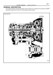
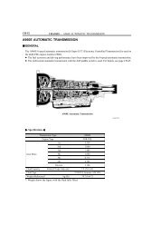
1. General information<br />
1.1 Picture of the transmission<br />
00/08/01 5 HP 19 FL © ZF Getriebe GmbH Saarbrücken CD<br />
1.1/1
1.2 Power flow diagram<br />
1st GEAR<br />
Input<br />
00/08/01<br />
2nd GEAR<br />
3rd GEAR 4th GEAR<br />
5th GEAR<br />
Reverse<br />
GEAR<br />
5 HP 19 FL © ZF Getriebe GmbH Saarbrücken<br />
CD<br />
1.2/1
00/08/01 5 HP 19 FL © ZF Getriebe GmbH Saarbrücken CD<br />
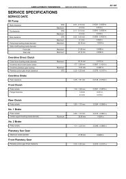
1.3 Specifications<br />
1.3.1 Screw specifications<br />
1.3.1.1 Differential cover<br />
Initial tightening of the screws is in the<br />
following order:<br />
7 ➮ 3 ➮ 11<br />
Then tighten the screws finally in<br />
numerical order (see diagram):<br />
1 ➮ 2 ➮ 3 ➮ ... ➮ 12<br />
Note:<br />
The numbers represent the actual final<br />
tightening order.<br />
(This is a simplification of Specification<br />
1060 700 134)<br />
(Tightening torques: see Chapter 1.5)<br />
1.3.1.2 Intermediate plate - pump -<br />
cylinder C<br />
Initial tightening of the screws is in the<br />
following order:<br />
1 ➮ 2 ➮ 3 ( = 10.220)<br />
Tighten screw 1, as long as piston C is<br />
build in.<br />
Then pretightening of the screws is in the<br />
following order:<br />
4 ➮ 5 ( = 10.100)<br />
Then tighten the screws finally in numerical<br />
order :<br />
6 ➮ 7 ➮ ... ➮ 11 ➮ 4 ➮ 5 (=10.100)<br />
➮ 12 (=10.120)<br />
➮ 13 (=10.160)<br />
➮ 14 ➮ ... ➮ 18 (=10.060/130)<br />
(Specification 1060 700 015)<br />
(Tightening torques: see Chapter 1.5)<br />
1.3/1
1.3.1.3Tightening yield strength crown gear differential<br />
Preconditions:<br />
• Crown gear, differential case and screws were washed and are dry<br />
• Parts should have room temperature<br />
The following data should be entered in the wrench:<br />
Tightening<br />
Mounting torque = 50 Nm<br />
Lower torque limit = 90 Nm<br />
Upper torque limit = 160 Nm<br />
Lower angle limit = 30°<br />
Upper angle limit = 70°<br />
Wrench case = hard<br />
Tighten srews crosswise.<br />
First tighten all screws to mounting torque<br />
and then to yield strength !<br />
Attention to the limit values!<br />
1.3/2 CD<br />
5 HP 19 FL © ZF Getriebe GmbH Saarbrücken<br />
00/08/01
98009<br />
98011<br />
98012<br />
00/08/01 5 HP 19 FL © ZF Getriebe GmbH Saarbrücken CD<br />
1.4 Making adjustments<br />
1.4.0 Measuring the clutch packs<br />
(procedure)<br />
Place the two intermediate pieces<br />
5p01 050 329/5p01 060 329 on the<br />
marked position on measuring fixture<br />
5p01 000 330.<br />
Using the knurled screw, turn adjusting<br />
device 5p01 001 458 to the upper limit.<br />
Attach force measuring unit<br />
5p01 000 329 to adjusting device.<br />
Fasten it with 4 knurled screws to the<br />
measuring fixture using the intermediate<br />
pieces.<br />
Using a fixing pin, connect measuring<br />
plate 5p01 040 330 with the force measuring<br />
unit.<br />
Using the knurled screw, clamp the<br />
clutch pack to be measured (with steel<br />
disc on the top and corrugated disc – if<br />
there is one – on the bottom) in the<br />
device at 200N.<br />
1.4/1
Check the value on the force measuring<br />
unit’s display.<br />
Then place measuring bar 5p01 060 330<br />
on the measuring plate, put the dial<br />
gauge’s measuring base in the measuring<br />
plate’s groove on the top disc of the set,<br />
and set the dial gauge to 0.<br />
Now use the measuring bar to measure<br />
down to the base plate.<br />
Read the measurement value ➮ M X<br />
Note!<br />
In each case, the X index in M X stands<br />
for the brake/ clutch clutch packs that are<br />
put in (A, B, C, D, E, F, G).<br />
1.4/2<br />
CD<br />
5 HP 19 FL © ZF Getriebe GmbH Saarbrücken<br />
98017<br />
98018<br />
00/08/01
98289<br />
98290<br />
00/08/01 5 HP 19 FL © ZF Getriebe GmbH Saarbrücken CD<br />
1.4.1 Clearances<br />
1.4.1.1Clearance, clutch F<br />
(snap ring)<br />
Determine installation space E F of brake<br />
F with measuring bar 5p01 000 330.<br />
To do this, place measuring bar<br />
5p01 000 330 on the edge of the cylinder<br />
of brake F. Apply the measuring base of<br />
the dial gauge to the highest point on the<br />
disc contact surface at the pressure plate<br />
and set the dial gauge to “0”.<br />
Pull the measuring sensor up, insert it<br />
into the snap ring groove and press it<br />
against the upper edge of the groove.<br />
Repeat the measurement twice after turning<br />
through 120°.<br />
Take an average of F 1 , F 2 , F 3 ➮ W F<br />
Determine thickness M F of clutch F disc<br />
set as described in Chapter 1.4.0<br />
“Measuring the clutch packs”.<br />
➮ M F<br />
Installation space E F is obtained from<br />
W F plus thickness of base F. ➮ E F<br />
Test value P F is then obtained from<br />
installation space E F minus M F<br />
Value P F must be between 3.10 and 4.89<br />
mm. Test specification 1060 700 062 -<br />
version B<br />
Select snap ring S F with test gauge P F .<br />
Calculation:<br />
E F = W F + F<br />
P F = E F - M F<br />
Clearance L F should be 1.9 - 2.2 mm<br />
with 5 lined discs.<br />
1.4/3
Example (for 1.4.1.1):<br />
F = 1.48 mm (base thickness)<br />
F1 F2 F3 W F<br />
M F<br />
E F<br />
P F<br />
S F<br />
= 29.78 mm<br />
= 29.75 mm<br />
= 29.75 mm<br />
= (29.78 + 29.75 + 29.75)/3<br />
= 29.76 mm<br />
= 27.2 mm<br />
= 29.76 + 1,48<br />
= 31.24 mm<br />
= 31.24 - 27.2<br />
= 4.04 mm<br />
=2.0 mm<br />
LF = 4.04 - 2.0<br />
➮ LF = 2.04 mm<br />
1.4/4 CD<br />
5 HP 19 FL © ZF Getriebe GmbH Saarbrücken<br />
00/08/01
99201<br />
98295<br />
00/08/01 5 HP 19 FL © ZF Getriebe GmbH Saarbrücken CD<br />
1.4.1.2Adjusting Clearance of brake D<br />
(snap ring)<br />
Determine installation space E D of brake<br />
D with measuring bar 5p01 000 330.<br />
To do this, place measuring bar 5p01 000<br />
330 on the edge of the cylinder of brake<br />
D. Place the base of the dial gauge on the<br />
highest point on the disc contact surface<br />
of the piston and set the dial gauge to<br />
“0”.<br />
Pull the measuring sensor up, insert it<br />
into the snap ring groove and press it<br />
against the upper edge of the groove.<br />
Repeat the measurement twice after turning<br />
through 120°.<br />
Take the average of D 1 , D 2 , D 3 ➮ W D<br />
Measure thickness M D of the disc set for<br />
brake D as described in Chapter 1.4.0<br />
“Measuring the clutch packs”.<br />
➮ M D<br />
Installation space E D is obtained from<br />
measured value W D plus base thickness<br />
F. ➮ E D<br />
Test value P D is then installation space<br />
E D minus disc set thickness M D<br />
Value P D must be between 4.65 - 6.45<br />
mm. Test specification 1056 700 265 -<br />
version A<br />
Use test gauge P D to select snap ring S D .<br />
Calculation:<br />
E D = W D + F<br />
P D = E D - M D<br />
Clearance L D should be 2.29 - 2.59 mm<br />
with six lined discs.<br />
1.4/5
Example (for 1.4.1.2):<br />
F = 1.48 mm (base thickness)<br />
D1 D2 D3 = 30.21 mm<br />
= 30.22 mm<br />
= 30.26 mm<br />
WD = (30.21 + 30.22 + 30.26)/3<br />
30.23 mm<br />
MD = 26.34 mm<br />
E D<br />
P D<br />
S D<br />
= 30.23 + 1.48<br />
= 31.71 mm<br />
= 31.71 - 26.34<br />
= 5.37 mm<br />
=3.0 mm<br />
LD = 5.37 - 3.0<br />
➮ LD = 2.37 mm<br />
1.4/6 CD<br />
5 HP 19 FL © ZF Getriebe GmbH Saarbrücken<br />
00/08/01
99202<br />
98297<br />
00/08/01 5 HP 19 FL © ZF Getriebe GmbH Saarbrücken CD<br />
1.4.1.3Adjusting Clearance of brake G<br />
(snap ring)<br />
Determine brake G installation space E G<br />
with measuring bar 5p01 000 330.<br />
To do this, place measuring bar 5p01 000<br />
330 on the edge of the cylinder of brake<br />
G. Place the base of the dial gauge<br />
against the highest point on the disc contact<br />
surface of the piston and set the dial<br />
gauge to “0”.<br />
Pull the measuring sensor up, insert in<br />
into the snap ring groove and press it<br />
against the upper edge of the groove.<br />
Repeat the measurement twice after<br />
turning through 120°.<br />
Take the average of G 1 , G 2 , G 3 ➮ W G<br />
Determine thickness M G of the disc set<br />
for brake G as described in Chapter<br />
1.4.0 “Measuring the clutch packs”.<br />
➮ M G<br />
Installation space E G is obtained from<br />
measured value W G plus base thickness<br />
F. ➮ E G<br />
Test value P G is then installation space<br />
E G minus M G<br />
Value P G should be between 3.41 and<br />
5.12 mm. Test specification 1056 700<br />
188, version A.<br />
Use test gauge P G to select snap ring S G .<br />
Calculation:<br />
E G = W G + F<br />
P G = E G - M G<br />
Clearance L G should be 1.52 - 1.82 mm<br />
with 4 lined discs.<br />
1.4/7
Example (for 1.4.1.3):<br />
F = 1.48 mm (base thickness)<br />
G1 G2 G3 = 21.98 mm<br />
= 21,97 mm<br />
= 21.99 mm<br />
W G = (21.98 + 21.97 + 21.99)/3<br />
= 21.98 mm<br />
M G = 19.23 mm<br />
E G<br />
P G<br />
S G<br />
= 21.98 + 1.48<br />
= 23.46 mm<br />
= 23.46 - 19.23<br />
= 4.23 mm<br />
=2.6 mm<br />
LG = 4.23 - 2.6<br />
➮ LG = 1.63 mm<br />
1.4/8 CD<br />
5 HP 19 FL © ZF Getriebe GmbH Saarbrücken<br />
00/08/01
98335<br />
98336<br />
00/08/01 5 HP 19 FL © ZF Getriebe GmbH Saarbrücken CD<br />
1.4.1.4Adjusting Clearance of clutch E<br />
(snap ring)<br />
Determine installation space E E of brake<br />
E with measuring bar 5p01 000 330.<br />
To do this, place measuring bar 5p01 000<br />
330 on the edge of the cylinder of brake<br />
E. Place the base of the dial gauge on the<br />
highest point of the disc contact surface<br />
on the piston and set the dial gauge to<br />
“0”.<br />
Pull the measuring sensor up, insert it<br />
into the snap ring groove and press it<br />
against the upper edge of the groove.<br />
Repeat the measurement twice after<br />
turning through 120°.<br />
Take the average of E 1 , E 2 , E 3 ➮ W E<br />
Determine thickness M E of the disc set<br />
for brake E as described in Chapter<br />
1.4.0 “Measuring the clutch packs”.<br />
➮ M E<br />
Installation space E E is obtained from<br />
measured value W E plus base thickness<br />
F. ➮ E E<br />
Test value P E is then installation space<br />
E E minus M E<br />
Value P E should be between 3.04 and<br />
4.46 mm. Test specification 1056 700<br />
309, version A<br />
Use test gauge P E to select snap ring S E .<br />
Calculation:<br />
E E = W E + F<br />
P E = E E - M E<br />
Clearance L E should be 1.78 - 2.08 mm<br />
with 5 lined discs.<br />
1.4/9
Example (for 1.4.1.4):<br />
F = 1.48 mm (base thickness)<br />
E1 E2 E3 W E<br />
M E<br />
E E<br />
P E<br />
S E<br />
= 23.22 mm<br />
= 23.23 mm<br />
= 23.27 mm<br />
= (23.22 + 23.23 + 23.27)/3<br />
= 23.24 mm<br />
= 21.64 mm<br />
= 23.24 + 1.48<br />
= 24.72 mm<br />
= 24.72 - 21.64<br />
= 3.08 mm<br />
=1.2 mm<br />
LE = 3.08- 1.2<br />
➮ LE = 1.88 mm<br />
1.4/10 CD<br />
5 HP 19 FL © ZF Getriebe GmbH Saarbrücken<br />
00/08/01
99200<br />
98343<br />
00/08/01 5 HP 19 FL © ZF Getriebe GmbH Saarbrücken CD<br />
1.4.1.5Adjusting Clearance of clutch A<br />
(snap ring)<br />
Determine clutch A installation space E A<br />
with measuring bar 5p01 000 330.<br />
To do this, place measuring bar 5p01 000<br />
330 on the edge of the cylinder of clutch<br />
A. Place the base of the dial gauge on the<br />
highest point of the disc contact surface<br />
at the piston and set the dial gauge to<br />
“0”.<br />
Pull the measuring sensor up, insert it<br />
into the snap ring groove and press it<br />
against the upper edge of the groove.<br />
Repeat the measurement twice, after<br />
turning through 120°.<br />
Take the average of A 1 , A 2 , A 3 ➮ W A<br />
Determine thickness M A of the disc set<br />
for clutch A as described in Chapter<br />
1.4.0 “Measuring the clutch packs”.<br />
➮ M A<br />
Installation space E A is obtained from<br />
measured value W A plus base thickness<br />
F. ➮ E A<br />
Test value P A is then installation space<br />
E A minus M A .<br />
Value P A must be between 2.83 and<br />
4.40 mm. Test specification 1056 700<br />
268, version A<br />
Use test gauge P A to select snap ring S A .<br />
Calculation:<br />
E A = W A + F<br />
P A = E A - M A<br />
Clearance L A should be 1.73 - 2.03 mm<br />
with five lined discs.<br />
1.4/11
Example (for 1.4.1.5):<br />
F = 1.48 mm (base thickness)<br />
A1 A2 A3 = 24.83 mm<br />
= 24.85 mm<br />
= 24.87 mm<br />
WD = (24.83 + 24.85 + 24.87)/3<br />
WA = 24.85 mm<br />
MA = 22.43 mm<br />
E A<br />
P A<br />
S A<br />
= 24.85 + 1.48<br />
= 26.33 mm<br />
= 26.33 - 22.43<br />
=3.9 mm<br />
=2.0 mm<br />
LA = 3.9 - 2.0<br />
➮ LA =1.9 mm<br />
1.4/12 CD<br />
5 HP 19 FL © ZF Getriebe GmbH Saarbrücken<br />
00/08/01
98349<br />
98350<br />
00/08/01 5 HP 19 FL © ZF Getriebe GmbH Saarbrücken CD<br />
1.4.1.6Adjusting Clearance of clutch B<br />
(snap ring)<br />
Determine clutch B installation space E B<br />
with measuring bar 5p01 000 330.<br />
To do this, place measuring bar 5p01 000<br />
330 on the edge of the cylinder of clutch<br />
B. Place the gase of the dial gauge<br />
against the highest point of the disc contact<br />
surface of the piston, and set the dial<br />
gauge to “0”.<br />
Pull the measuring sensor up, insert it<br />
into the snap ring groove and press it<br />
against the upper edge of the groove.<br />
Repeat the measurement twice after<br />
turning by 120°.<br />
Take the average of B 1 , B 2 , B 3 ➮ W B<br />
Determine the thickness M B of the<br />
clutch B disc set as described in Chapter<br />
1.4.0 “Measuring the clutch packs”.<br />
➮ M B<br />
Installation space E C is obtained from<br />
measured value W B plus base thickness<br />
F. ➮ E B<br />
Test value P B is then installation space<br />
E B minus M B<br />
Value P B should be between 1.87 and<br />
2.64 mm. Test specification 1056 700<br />
236, version B<br />
Use test gauge P B to select snap ring S B .<br />
Calculation:<br />
E B = W B + F<br />
P B = E B - M B<br />
Clearance L B should be 0.64 - 0.94 mm<br />
with 2 lined discs.<br />
1.4/13
Example (for 1.4.1.6):<br />
F = 1.48 mm (base thickness)<br />
B1 B2 B3 W B<br />
M B<br />
E B<br />
P B<br />
S B<br />
= 14.11 mm<br />
= 14.15 mm<br />
= 14.16 mm<br />
= (14.11 + 14.15 + 14.16)/3<br />
= 14.14 mm<br />
= 13.43 mm<br />
= 14.14 + 1.48<br />
= 15.62 mm<br />
= 15.62 - 13.43<br />
= 2.19 mm<br />
= 1.4 mm<br />
LB = 2.19 mm - 1.4 mm<br />
➮ LB = 0.79 mm<br />
1.4/14 CD<br />
5 HP 19 FL © ZF Getriebe GmbH Saarbrücken<br />
00/08/01
99216<br />
99217<br />
00/08/01 5 HP 19 FL © ZF Getriebe GmbH Saarbrücken CD<br />
1.4.1.7Adjusting Clearance of brake C<br />
(snap ring)<br />
Screw the cylinder to the oil supply with 2<br />
M6 x 16 screws (tightening torque 8 Nm).<br />
Determine installation space E C for brake C<br />
with measuring bar 5p01 000 330 .<br />
To do this, place measuring bar 5p01 000 330<br />
on the edge of the cylinder for brake C. Place<br />
the base of the dial gauge against the piston at<br />
the highest point on the disc contact surface<br />
and set the dial gauge to “0”. Pull the measuring<br />
sensor up, insert it into the snap ring<br />
groove and press it against the upper edge of<br />
the groove. Repeat the measurement twice<br />
after turning through 120°.<br />
Take the average of C 1 , C 2 , C 3 ➮ W C<br />
Important:<br />
Remove the screws again afterwards.<br />
Determine thickness M C of the brake C<br />
disc set as described in Chapter 1.4.0<br />
“Measuring the clutch packs”.<br />
➮ M C<br />
Installation space E C is obtained from<br />
measured value W C plus base thickness<br />
F. ➮ E C<br />
Test value P C is then installation space<br />
E C minus M C<br />
Value P C should be between 3.16 and<br />
4.40 mm. Test specification 1056 700<br />
264, version B<br />
Use test gauge P C to select snap ring S C .<br />
Calculation:<br />
E C = W C + F<br />
P C = E C - M C<br />
Clearance L C should be 1.63 - 1.93 mm<br />
with 4 lined discs.<br />
1.4/15
Example: (for 1.4.1.7)<br />
F = 1.48 mm (base thickness)<br />
C1 C2 C3 = 20.82 mm<br />
= 20.8 mm<br />
= 20.84 mm<br />
WC = (20.82 + 20.8 + 20.84)/3<br />
= 20.82 mm<br />
MC = 18.78 mm<br />
E C<br />
P C<br />
S C<br />
= 20.82 + 1.48<br />
= 22.3 mm<br />
= 22.3 - 18.78<br />
= 3.52 mm<br />
=1.8 mm<br />
LC = 3.52 mm - 1.8 mm<br />
➮ LC = 1.72 mm<br />
1.4/16 CD<br />
5 HP 19 FL © ZF Getriebe GmbH Saarbrücken<br />
00/08/01
99139<br />
99140<br />
99141<br />
00/08/01 5 HP 19 FL © ZF Getriebe GmbH Saarbrücken CD<br />
1.4.2 Preload, differential<br />
Determine total washer thickness M G . To<br />
do this, measure shim thickness 35.080,<br />
and 35.120 ➮ M U , M O<br />
Insert the shim 35.120 previously<br />
removed into the differential cover with<br />
bearing race 35.150/110.<br />
This can normally be done by hand, but<br />
if necessary heat the bearing seat lightly<br />
with a hot air blower.<br />
Calculation:<br />
MG = MU + MO Insert the shim 35.080 previously<br />
removed into the transmission housing<br />
with the bearing race.<br />
This can normally be done by hand, but<br />
if necessary heat the bearing seat lightly<br />
with a hot air blower.<br />
Install the differential in the transmission<br />
housing and fit the differential cover.<br />
Important !<br />
There must be a gap (app. 0.1 - 0.3 mm)<br />
between the transmission housing and the<br />
differential cover. Check with a feeler gauge.<br />
Note risk of distortion if the gap is too<br />
large, e.g. 0.7 mm. ➮ preload too high.<br />
In this case, first reduce the thickness of<br />
the shim, e.g. in the differential cover, by<br />
0.5 mm.<br />
Measure with no shaft sealing ring and Oring<br />
in the differential cover.<br />
1.4/17
Tighten the differential cover with<br />
4 screws 35.184 at 90-degree intervals.<br />
Place measuring plate 5p01 000 353 on<br />
the differential cover.<br />
(Tightening torques: see Chapter 1.5)<br />
Screw post 5p01 020 347 of the<br />
measuring stand with M10 thread into<br />
the matching tapped hole in the transmission<br />
housing. Clamp cross-holder<br />
5p01 010 347 so that the dial gauge<br />
sensor is central and at a right angle to<br />
the measuring plate.<br />
Set the dial gauge to “0”.<br />
Slacken off the 4 screws by 1/2 turn each<br />
in a crosswise pattern until they are<br />
loose, but the dial gauge reading does not<br />
change.<br />
➮ Read off value M D .<br />
Important:<br />
The measuring stand must not be touched<br />
or an incorrect reading will be obtained.<br />
1.4/18<br />
CD<br />
5 HP 19 FL © ZF Getriebe GmbH Saarbrücken<br />
99142<br />
99143<br />
99144<br />
00/08/01
00/08/01 5 HP 19 FL © ZF Getriebe GmbH Saarbrücken CD<br />
According to test specification 1056 700<br />
282, measured value M D must be between<br />
M Dmin = 0.18mm und M Dmax =<br />
0.28 mm preload.<br />
If the correct value is not obtained,<br />
determine the desired thickness and<br />
check again.<br />
Calculation:<br />
DD = MD - [MDmin to MDmax ]<br />
D = MD - [MDmax + MDmin ] / 2<br />
MGV = DD (change limit)<br />
D M (choosen average value from D D )<br />
Remove the measuring stand and plate.<br />
Take off the cover.<br />
Remove the differential, bearing races<br />
and shims.<br />
Adjusting shims 35.080 and 35.120 are<br />
available in thickness steps of 0.05 mm.<br />
Alter the shims (total shim thickness<br />
from check M GV ) according to the<br />
average D D value.<br />
D M > 0 => reduce shim thickness<br />
D M < 0 => increase shim thickness<br />
D M = 0 => leave shim thickness<br />
unchanged<br />
1.4/19
Example:<br />
MD MU MO = 0.38 mm (preload)<br />
= 1.35 mm<br />
= 1.25 mm<br />
MGV DD = 1.35 + 1.25 = 2.6 mm<br />
= 0.38 - [0.18 to 0.28]<br />
= 0.1 to 0.2 mm<br />
DM = 0.38 - [0.28 + 0.18]/ 2<br />
= 0.15 mm<br />
M GV reduced by 0.15 mm<br />
➮ M GA = 2.45 mm<br />
[total measured shim thickness]<br />
Repeat the measuring procedure with<br />
M GA = 2.45 mm.<br />
➮ M D = 0.23 mm (preload)<br />
➮ correct according to test specification<br />
1.4/20 CD<br />
5 HP 19 FL © ZF Getriebe GmbH Saarbrücken<br />
00/08/01
99136<br />
99137<br />
00001<br />
00/08/01 5 HP 19 FL © ZF Getriebe GmbH Saarbrücken CD<br />
1.4.3 Bevel gear drive<br />
1.4.3.1 Determining pinion position<br />
Turn the transmission through 90° (converter<br />
bell facing down).<br />
Insert fixture 5p01 002 706 into differential<br />
housing with measuring radius facing<br />
bore in pinion shaft.<br />
Set measuring element 5p01 002 706 in<br />
calibrating device 5p89 004 524 to zero.<br />
Reference dimension = 93.6 mm<br />
(calibrating device)<br />
Adjust according to instruction 1056 700<br />
282 [washer thickness steps = 0.03 mm]<br />
Place measuring element in transmission<br />
housing on the bearing contact surface.<br />
Read off dimension MR (measuring pin<br />
at measuring radius). Turn the transmission<br />
back through 90°.<br />
Overall dimension G is obtained from the<br />
calibrating device measurement MER plus the measuring radius MMR and the<br />
measured dimension MR .<br />
Calculation:<br />
G = M ER + M MR + M R<br />
Note: !<br />
M R can also be negative; note direction<br />
of dial gauge pointer movement.<br />
1.4.3.2 Installed bearing height pinion<br />
shaft bearing<br />
Place the differential-side inner bearing<br />
race on the measuring plate.<br />
Insert the outer bearing race in measuring<br />
sleeve 5p01 030 355 and place it on the<br />
bearing race.<br />
Attach weight 5p01 010 355 and place<br />
centrally under the dial gauge sensor.<br />
Set the dial gauge to “0”.<br />
Raise the measuring sensor and pull the<br />
measured component set forwards.<br />
Take off the weight and remove the outer<br />
bearing race from the measuring sleeve.<br />
1.4/21
Place the differential-side inner bearing<br />
race on the measuring plate.<br />
Place the outer bearing race on the inner<br />
race and apply weight 5p01 010 355.<br />
Place the set of components to be<br />
measured centrally under the dial gauge<br />
sensor.<br />
Rotate the bearing several times. Read<br />
off dimension ➮ M L<br />
Installed bearing height L is sleeve height<br />
H H minus M L<br />
Calculation:<br />
L = H H - M L<br />
Read off pinion dimension R.<br />
The shim for adjusting pinion position S<br />
is obtained from<br />
Calculation:<br />
S = G - L - R<br />
Example:<br />
MER = 93.6 mm<br />
MMR = 60 mm<br />
MR = -0.03 mm<br />
R = 96 mm<br />
H H = 57 mm<br />
M L = - 0.76 mm<br />
G = 93.6 + 60 - 0.03<br />
= 153.57 mm<br />
L = 57 - 0.76<br />
= 56.24 mm<br />
S = 153.57 - 56.24 - 96<br />
= 1.33 mm<br />
1.4/22<br />
CD<br />
5 HP 19 FL © ZF Getriebe GmbH Saarbrücken<br />
00002<br />
00/08/01
00019<br />
00/08/01 5 HP 19 FL © ZF Getriebe GmbH Saarbrücken CD<br />
Select the correct washer.<br />
The washer may be max. 0.02 mm larger<br />
than the nominal dimension, but not<br />
smaller.<br />
➮ S = 1,33 mm<br />
1.4.3.3 Determining backlash /<br />
crown wheel position<br />
Note:<br />
Experience has shown that the washer in<br />
the differential cover is 0.1 - 0.5 mm<br />
thinner than the washer in the differential<br />
housing.<br />
D G = 0.1 - 0.5 mm<br />
Calculation:<br />
M U = (M GA + D G ) / 2<br />
M O = M GA - M U<br />
Install the washer and the outer bearing<br />
race in the transmission housing.<br />
Install the differential in the transmission<br />
housing.<br />
Add the washer and outer bearing race to<br />
the cover.<br />
1.4/23
Screw the cover to the transmission<br />
housing, using 4 screws in a crosswise<br />
pattern, making sure that backlash is not<br />
lost..<br />
Backlash can be checked by turning the<br />
pinion shaft.<br />
Rotate the pinion shaft by approx. 15<br />
turns.<br />
(Tightening torques: see Chapter 1.5)<br />
Important:<br />
Measure without the O-ring seal on the<br />
differential cover<br />
Clamp backlash measuring disc 5p01 000<br />
354 to the pinion shaft.<br />
Screw the column of measuring stand<br />
5p01 020 347 into the transmission<br />
housing and clamp cross-holder 5p01<br />
010 347 so that the measuring sensor is<br />
at a right angle on the marked measuring<br />
area of the measuring disc.<br />
Turn the pinion shaft in one direction<br />
until the pinion/crown wheel teeth make<br />
contact.<br />
Set the dial gauge to “0”.<br />
Turn the pinion carefully as far as<br />
possible in the opposite direction.<br />
Repeat the procedure twice after turning<br />
the pinion shaft through 360° and take<br />
the average value of the readings M 1 , M 2<br />
and M 3 ➮ M F<br />
Backlash M F must be between 0.27 and<br />
0.37 mm according to specification 1056<br />
700 282.<br />
1.4/24<br />
CD<br />
5 HP 19 FL © ZF Getriebe GmbH Saarbrücken<br />
00020<br />
00021<br />
00022<br />
00/08/01
Example:<br />
00/08/01 5 HP 19 FL © ZF Getriebe GmbH Saarbrücken CD<br />
M F > permitted value: M F too thick<br />
M F < permitted value: M F too thin<br />
Warning!<br />
If the nominal backlash value is not<br />
obtained, recalculate shim thickness, but<br />
do not alter the overall shim thickness.<br />
Repeat the measurement.<br />
Afterwards, remove the measuring stand<br />
and disc.<br />
Unscrew and remove the differential<br />
cover.<br />
MGA = 2.45 mm<br />
DG = 0.25 mm<br />
(selected washer thickness<br />
difference)<br />
1st measurement:<br />
MU = (2.45 + 0.25) / 2<br />
= 1.35 mm<br />
MO = 2.45 - 1.35<br />
= 1.1 mm<br />
Measured backlash:<br />
MF = 0.4 mm<br />
➮ incorrect!<br />
M F > permitted value ➮ reduce M U :<br />
2nd measurement:<br />
MU = 1.30 mm<br />
MO = 2.45 - 1.30<br />
= 1.15 mm<br />
Measured backlash:<br />
MF = 0.35 mm<br />
➮ correct!<br />
1.4/25
1.4.4 Detent spring switch<br />
Using a suitable tool or by hand, set the<br />
detent disc to position N (Neutral).<br />
Mount position gauge 5p01 002 609 on<br />
the selector shaft and turn the gauge until<br />
the locating pin in the transmission housing<br />
engages in the gauge, then turn the<br />
knurled screw to eliminate play.<br />
Align the detent spring with centring<br />
device 5x46 001 250 and in this position<br />
screw the spring down.<br />
Tighten the screw at the output end first.<br />
(Tightening torques: see Chapter 1.5)<br />
With auxiliary tool 5w04 000 583 turn<br />
forward until distorsion angle is reached<br />
Unscrew the position gauge, move the<br />
selector shaft to all positions in turn and<br />
then move it back to position “N”.<br />
Note !<br />
If assembly was correct, it should be easy<br />
to push the position gauge on to the<br />
selector shaft until it makes contact with<br />
the transnission housing.<br />
1.4/26<br />
CD<br />
5 HP 19 FL © ZF Getriebe GmbH Saarbrücken<br />
00028<br />
00029<br />
00030<br />
00/08/01
00032<br />
00033<br />
00/08/01 5 HP 19 FL © ZF Getriebe GmbH Saarbrücken CD<br />
1.4.5 Output play (shim)<br />
1.4.5.1 Installation space, output<br />
Output endplay according to the parts list<br />
is 0.15 bis 0.35 mm.<br />
Place fixture 5p01 010 356 on measuring<br />
ring 5p01 030 356 and set the dial to “0”.<br />
Place thrust bearing 37.030 over input<br />
shaft.<br />
Place the fixture over the output shaft on<br />
the thrust bearing and turn it several<br />
times.<br />
Read off measured value M 1 at the dial.<br />
Repeat the measurement twice after turning<br />
on through 120° to a new position,<br />
then take the average of the three values<br />
M 1 , M 2 , M 3 ➮ M A<br />
Calculation:<br />
M A = (M 1 + M 2 + M 3 ) / 3<br />
Lift the measuring fixture und the thrust<br />
baring off the transmission.<br />
The insertion depth is obtained as<br />
follows:<br />
Calculation:<br />
M TA = K A - M A<br />
Note !<br />
K A = engraved on the fixture.<br />
M A = measured value<br />
1.4/27
1.4.5.2 Pinion projection<br />
Insert the complete pinion with the<br />
closed side first into the front-axle<br />
housing.<br />
Turn the pinion several times.<br />
Place the dial gauge from measuring bar<br />
5p01 150 331 on measuring ring 5p01<br />
020 356 and set to “0”.<br />
Place the measuring ring on the frontaxle<br />
housing, place measuring ring 5p01<br />
040 356 on the pinion and measured as<br />
far as the measuring ring with the<br />
measuring bar ➮ M R<br />
Calculation:<br />
Pinion projection is obtained as follows:<br />
M RA = K RV - K RR + M R - K D<br />
Washer thickness is obtained as follows :<br />
S M = (S MIN + S MAX ) / 2<br />
S R = M TA - M RA - S M<br />
1.4/28<br />
CD<br />
5 HP 19 FL © ZF Getriebe GmbH Saarbrücken<br />
00034<br />
00035<br />
00036<br />
00/08/01
Example: (for 1.4.5)<br />
00/08/01 5 HP 19 FL © ZF Getriebe GmbH Saarbrücken CD<br />
KD KA KRR = 0.26 mm (gasket thickness)<br />
= 30 mm<br />
= 8 mm (measuring ring thickness,<br />
engraved on)<br />
KRV = 30.045 mm ( “ )<br />
S MIN = 0.15 mm<br />
S MAX = 0.35 mm<br />
M R<br />
M1 M2 M3 M A<br />
S M<br />
= -6.249 mm<br />
= 10.68 mm<br />
= 10.73 mm<br />
= 10.71 mm<br />
=(10.68 + 10.73 + 10.71)/3<br />
= 10.71 mm<br />
= (0.15 + 0.35) / 2<br />
= 0.25 mm<br />
M TA = 29.97 - 10.71<br />
= 19.26 mm<br />
M RA = 30.045 - 8 + (-6.249) - 0.26<br />
= 15.536 mm<br />
S R<br />
= 19.26 - 15.536 - 0.25<br />
= 3.474 mm<br />
Install washer S from optional technical<br />
kit (OTK) that is closest to the value S R<br />
determined in this way.<br />
choosen:<br />
➮ S = 3.5 mm<br />
1.4/29
1.4.6 Bearing adjustment, output<br />
gears<br />
1.4.6.0 Preparation for bearing adjustment,<br />
shim washers<br />
Place front axle housing on baseplate<br />
5x46 001 275.<br />
Install the pinion, helical and intermediate<br />
gear into the front axle housing<br />
in the correct positions.<br />
Place the gasket on the front axle<br />
housing.<br />
Important! (to avoid falsifying the<br />
measurement)<br />
The inscriptions on the gearwheels face<br />
down, into the front axle housing.<br />
Place measuring plate 5p01 002 704 on<br />
the front axle housing. Insert centring<br />
ring 5p01 070 357 into helical gear hole<br />
in measuring plate.<br />
Place the bearing shells on the pinion,<br />
helical and intermediate gears.<br />
Insert and tighten all screws through the<br />
front axle housing into the measuring<br />
plate. Place gearwheel holding plate 5x46<br />
002 173 on the measuring plate and<br />
secure it with 2 screws.<br />
Lift the front axle housing off the baseplate.<br />
Turn through 180° with handles on<br />
gearwheel retaining plate, and set the<br />
housing down on the handles.<br />
Next, tighten all screws.<br />
Place the front axle housing (turned<br />
through 180°) back in the baseplate and<br />
remove the gearwheel retaining plate.<br />
(Tightening torques: see Chapter 1.5)<br />
1.4/30<br />
CD<br />
5 HP 19 FL © ZF Getriebe GmbH Saarbrücken<br />
00009<br />
00010<br />
00012<br />
00/08/01
00046<br />
00047<br />
00048<br />
00/08/01 5 HP 19 FL © ZF Getriebe GmbH Saarbrücken CD<br />
1.4.6.1 Projection, pinion bearing<br />
Place thrust bell 5p01 030 357 on the<br />
measuring plate.<br />
Place measuring bridge 5p01 010 357<br />
over the thrust bell.<br />
Place measuring bar 5p01 150 331 on the<br />
measuring bridge and set the dial on the<br />
thrust bell to “0”.<br />
Place the thrust bell on the pinion bearing<br />
outer race, place spring 5p01 000 357<br />
over the thrust bell and secure the measuring<br />
bridge over the thrust bell with 2<br />
screws M8x80 inserted into the tapped<br />
holes provided in the measuring plate.<br />
(Tightening torques = 10 Nm)<br />
Turn the gearwheels.<br />
Place the measuring bar on the<br />
measuring bridge and measure the thrust<br />
bell.<br />
Read off value M DR .<br />
Note!<br />
Continue to turn the gearwheels until the<br />
value remains constant.<br />
1.4/31
1.4.6.2 Projection, helical/intermediate<br />
gear bearing<br />
Use the same procedure as for the pinion,<br />
helical gear and intermediate gear.<br />
Measure values M DS (helical gear) and<br />
M DZ (intermediate gear).<br />
After measuring gearwheel projection,<br />
dismantle the measuring equipment.<br />
Important!<br />
Use thrust bell 5p01 020 357 for the<br />
intermediate gear.<br />
1.4/32 CD<br />
5 HP 19 FL © ZF Getriebe GmbH Saarbrücken<br />
00/08/01
00013<br />
00014<br />
00/08/01 5 HP 19 FL © ZF Getriebe GmbH Saarbrücken CD<br />
1.4.6.3 Installation space, pinion<br />
Place measuring ring 5p01 040 357 in<br />
pinion bearing hole.<br />
Set the dial to “0” with measuring bar<br />
5p01 150 331 against the transmission<br />
housing sealing face.<br />
Note:<br />
The measuring ring must be correctly<br />
seated in the bore.<br />
Cleanliness is essential!<br />
Place the dial gauge centrally on the<br />
measuring ring and read off value M RR ➮<br />
M RR<br />
1.4.6.4 Installation space, intermediate<br />
gear<br />
For the intermediate gear, follow the<br />
same procedure as for the pinion.<br />
Determine value M RZ ➮ M RZ<br />
Note:<br />
A different measuring ring, 5p01 050<br />
357, is used.<br />
1.4/33
1.4.6.5 Installation space, helical gear<br />
Press bearing race 35.190 into transmission<br />
housing.<br />
Place measuring ring 5p01 040 357 in<br />
pinion bearing hole.<br />
Measure with measuring bar 5p01 150<br />
331 on bearing race against the transmission<br />
housing sealing face and set the dial<br />
to “0”.<br />
Measure down on bearing race and determine<br />
value M RS ➮ M RS<br />
Abbreviations:<br />
K VR/RS = meas. ring thickness 5p01 040 357<br />
K RZ = measuring ring thickness 5p01 050 357<br />
K P = measuring plate thickness 5p01 002 704<br />
(pinion, helical and intermediate gears)<br />
NR , NS , NZ = zero line<br />
BR , BS , BZ = installation space<br />
HR , HS , HZ = projection<br />
MRR , MRS , MRZ = installation space<br />
measured value<br />
MDR , MDS , MDZ = projection measured<br />
value<br />
SR , SS , SZ SPR , SPS VZ = washer thickness<br />
= play<br />
= preload<br />
1.4/34<br />
CD<br />
5 HP 19 FL © ZF Getriebe GmbH Saarbrücken<br />
00015<br />
00016<br />
00/08/01
00/08/01 5 HP 19 FL © ZF Getriebe GmbH Saarbrücken CD<br />
1.4.6.6 Determining shim thickness –<br />
pinion, helical and intermediate gears<br />
The washer thicknesses can be<br />
determined from the measured values.<br />
Calculation:<br />
B R = K RR - M RR<br />
B S = K RS - M RS<br />
B Z = K RZ - M RZ<br />
H R = K P + M DR<br />
H S = K P + M DS<br />
H Z = K P + M DZ<br />
NR =BR - HR NS = BS - HS NZ = BZ - HZ S R = N R - S PR<br />
S S = N S - S PS<br />
S Z = N Z - V Z<br />
Attention! (important!)<br />
The K-measures of the measuring rings<br />
and measuring plates are engraved in the<br />
parts.<br />
Please use the K-measures of your measuring<br />
rings and -plates.<br />
Adjusting values (acc. to parts list)<br />
Pinion: (play)<br />
Setting: 0 to 0.05 mm<br />
Test value: -0.03 to 0.08 mm<br />
Helical gear: (play)<br />
Setting: 0 to 0.05 mm<br />
Test value: -0.03 to 0.08 mm<br />
Intermediate gear: (preload)<br />
Setting: - 0.03 to - 0.08 mm<br />
Test value: 0 to - 0.11 mm<br />
Important !<br />
Note the meaning of the +/- sign:<br />
+ means play (clearance);<br />
- means preload<br />
1.4/35
Example: (for 1.4.6)<br />
Pinion:<br />
KRR = 15.466 mm<br />
KP = 25.002 mm<br />
MRR = -0.627 mm<br />
MDR = -10.372 mm<br />
SPR = 0 bis 0.5 mm<br />
BR = 15.466 - (-0.627)<br />
= 16.093 mm<br />
HR = 25.002 + (-10.372)<br />
= 14.63 mm<br />
NR = 16.093 - 14.63<br />
= 1.463 mm<br />
SR = 1.45 mm selected<br />
➮ SPR = 0.013 mm (play)<br />
Helical gear:<br />
KRS = 15.466 mm<br />
KP = 25.002 mm<br />
MRS = -0.629 mm<br />
MDS = -10.33<br />
SPS = 0 bis 0.5 mm<br />
BS = 15.466 - (-0.629)<br />
= 16.095 mm<br />
HS = 25.002 + (-10.33)<br />
= 14.672 mm<br />
NR = 16.095 - 14.672<br />
= 1.423 mm<br />
SS = 1.4 mm selected<br />
➮ SPS = 0.023 mm (play)<br />
Intermediate gear:<br />
KRZ = 15.47 mm<br />
KP = 25.002 mm<br />
MRZ = -0.617 mm<br />
MDZ = -10.14 mm<br />
VZ = - 0.03 bis -0.08 mm<br />
BZ = 15.47 - (-0.617)<br />
= 16.087 mm<br />
HZ = 25.002 + (-10.14)<br />
= 14.862 mm<br />
NZ = 16.087 - 14.682<br />
= 1.405 mm<br />
SZ ➮ VZ = 1.45 mm selected<br />
= -0.045 mm (preload)<br />
1.4/36 CD<br />
5 HP 19 FL © ZF Getriebe GmbH Saarbrücken<br />
00/08/01
99222<br />
00/08/01 5 HP 19 FL © ZF Getriebe GmbH Saarbrücken CD<br />
1.4.7 Play at input (washer)<br />
Attach the oil supply with at least two<br />
machine screws in opposed positions.<br />
(Tightening torques: see Chapter 1.5)<br />
Clamp measuring fixture 5p01 002 379<br />
on the input shaft about 2 mm above the<br />
stator shaft, so that no play is present. Set<br />
the dial to “0”.<br />
Initial requirement:<br />
Needle thrust bearing 10.390 and the<br />
thinnest shim 10.400 (S D = 1 mm) have<br />
been placed in position.<br />
Determine endplay by pressing and pulling<br />
the handle (repeat the measurement).<br />
Nominal endplay D = 0.05 - 0.35 mm<br />
acc. to test specification 1056 700 203.<br />
Take measurements M 1 ,M 2 and determine<br />
the average value ➮ M<br />
Calculation:<br />
M = (M1+ M2)/2<br />
S = M + SD - D<br />
If there is a deviation, install a correspondingly<br />
thicker shim washer 10.400.<br />
To do this, take off the oil supply and the<br />
input and install the shim of determined<br />
thickness in place of the original shim.<br />
Then re-install the components according<br />
to 3. Assembly of input with oil supply.<br />
Check endplay again.<br />
1.4/37
Example (for 1.4.7):<br />
M1 = 0.88 mm<br />
M2 = 0.86 mm<br />
SD = 1.00 mm<br />
D = 0.05 to 0.35 mm<br />
M = (0.88+ 0.86)/2 = 0.87 mm<br />
S = 0.87 + 1.00 - (0.05 to 0.35)<br />
= 1.87 - (0.05 to 0.35)<br />
= 1.52 bis 1.82 mm<br />
Selected:<br />
➮ S = 1.7 mm<br />
1.4/38 CD<br />
5 HP 19 FL © ZF Getriebe GmbH Saarbrücken<br />
00/08/01
1.5 Tightening torques<br />
No. Designation Part List- Wrench size Page Tightening<br />
Item-No. No. torque [Nm]<br />
1 Hex bolt 09.120 Hex, 1.3/1<br />
(differential) 17 mm 3.1/3 Yield limit!<br />
2 Slotted nut 35.030 Wrench 3.1/5 120 Nm<br />
(pinion shaft) 5x46 002 174 (± 12 Nm)<br />
3 Countersunk screw 01.440 TORX - TX 27 3.1/6 10 Nm<br />
(pinion shaft bearing) (± 1 Nm)<br />
4 Machine screw 35.150/150 TORX - TX 27 3.1/8 8 Nm<br />
(oil baffle plate) (± 0.8 Nm)<br />
5 Machine screw 35.184 TORX - TX 40 1.4/18 23 Nm<br />
(differential) 1.4/24 (± 2.3 Nm)<br />
3.1/8<br />
6 Machine screw 01.200 TORX - TX 27 H 1.4/26 4 (+0.5) Nm<br />
(detent spring) 3.2/2 + 15º (+5º)<br />
7 Machine screw 01.080 TORX - TX 40 3.2/4 23 Nm<br />
(guide plate) (± 2.3 Nm)<br />
8 Machine screw 37.220 TORX - TX 40 1.4/30 23 Nm<br />
(front axle housing) 3.4/2 (± 2.3 Nm)<br />
9 Machine screw (pump) 10.160 TORX - TX 27 1.3/1 5 Nm<br />
(disc carrier, cyl. C) 10.220 3.7/3 (± 0.5 Nm)<br />
10 Machine screw 10.100 TORX - TX 27 1.3/1 5 Nm<br />
(pre-tightening pump) 3.7/3 (± 0,5 Nm)<br />
(final tightening pump) 10.100 TORX - TX 27 1.3/1 10 Nm<br />
(stator shaft) 10.060/130 3.7/3 (± 1 Nm)<br />
11 Machine screw 10.440 TORX - TX 27 1.4/37 10 Nm<br />
(oil supply) 3.7/6 (± 1 Nm)<br />
12 Machine screw 35.250 TORX - TX 40 3.8/3 23 Nm<br />
(side shaft) (± 2.3 Nm)<br />
13 Expansion bolt 35.200 TORX - TX 40 3.8/3 25 Nm<br />
(flange) (± 2.5 Nm)<br />
14 Machine screw 01.140 TORX - TX 27 3.9/3 10 Nm<br />
(inductive sensor) (± 1 Nm)<br />
00/08/01 5 HP 19 FL © ZF Getriebe GmbH Saarbrücken CD<br />
1.5/1
No. Designation Part List- Wrench size Page Tightening<br />
Item-No. No. torque [Nm]<br />
15 Machine screw 27.400 TORX - TX 27 3.8/3 8 Nm<br />
(valve body) 27.410 (± 0.8 Nm)<br />
16 Machine screw 27.440 TORX - TX 27 3.9/4 5 Nm<br />
(Ölfilter) (± 0.5 Nm)<br />
17 Machine screw 03.040 TORX - TX 27 3.9/4 10 Nm<br />
(oil pan) (± 1 Nm)<br />
18 Filler plug M30x1.5 03.130 Intl. hex 3.9/4 80 Nm<br />
(oil pan) 17 mm (± 8 Nm)<br />
19 Drain plug M16x1.5 03.120 Intl. hex 3.9/4 40 Nm<br />
(oil pan) 8 mm (± 4 Nm)<br />
20 Filler plug M18x1.5 35.370 Intl. hex 3.9/5 35 Nm<br />
(differential) 8 mm (± 3.5 Nm)<br />
21 Machine screw 01.430 TORX - TX 27 3.9/6 8 Nm<br />
(position switch) (± 0.8 Nm)<br />
22 Hex screw (M12x70) 22.120 (incl. nut) 3.9/8 15 Nm<br />
(converter retaining bracket) 19 mm (± 1.5 Nm)<br />
23 Hex screw (M10x14) 22.130 3.9/8 15 Nm<br />
( converter retaining bracket) 17 mm (± 1.5 Nm)<br />
1.5/2 CD<br />
5 HP 19 FL © ZF Getriebe GmbH Saarbrücken<br />
00/08/01
1.6 Transmission test (test bench)<br />
The following points must be checked:<br />
Correct oil level<br />
Proper oil level; observe the vehicle manufacturer’s specifications and Part List.<br />
Oil level too low<br />
This can result in:<br />
– Engine over-revving or no power flow in curves or when starting from a stop<br />
– Valve chatter due to air pockets in the oil<br />
– General malfunctions<br />
Among other things, burned clutches can be the result.<br />
Oil level too high<br />
Danger of loss due to splashing, formation of foam, strong increases in temperature at high<br />
road speeds. Loss of oil via breather; among other things, burned clutches and shifting<br />
problems can result.<br />
Proper engine settings<br />
Correct idle speed; follow specifications from vehicle manufacturer.<br />
Power flow, forward and reverse<br />
Correct adjustment of selector linkage or control cable; observe the vehicle manufacturer’s<br />
specifications.<br />
00/08/01 5 HP 19 FL © ZF Getriebe GmbH Saarbrücken CD<br />
1.6/1
1.7 Special tools<br />
98008<br />
98034<br />
00045<br />
OBJECT Order-No. / Application<br />
Remarks<br />
1<br />
2<br />
3<br />
5p01 000 329<br />
-Force measuring unit<br />
5p01 000 330<br />
-Measuring fixture, clutch play<br />
(Measuring plate:<br />
- short neck >20 mm<br />
- long neck
Remarks<br />
1.7/2<br />
Order-No. / Application OBJECT<br />
5p01 000 353<br />
Preload measuring plate<br />
5p01 000 354<br />
Backlash measuring fixture<br />
5p01 000 355<br />
Measuring fixture for installed<br />
bearing height, pinion shaft<br />
CD<br />
5 HP 19 FL © ZF Getriebe GmbH Saarbrücken<br />
4<br />
5<br />
6<br />
00049<br />
00050<br />
00051<br />
00/08/01
00108<br />
00053<br />
97301<br />
OBJECT Order-No. / Application<br />
Remarks<br />
7<br />
8<br />
9<br />
5p01 000 356<br />
Measuring device, output play<br />
5p01 000 357<br />
Preload measuring plate (300N)<br />
5p01 001 458<br />
-Adjusting device, preload<br />
Identical<br />
4 HP 18 Q<br />
4 HP 20<br />
5 HP 190<br />
5 HP 24<br />
00/08/01 5 HP 19 FL © ZF Getriebe GmbH Saarbrücken CD<br />
1.7/3
Remarks<br />
1.7/4<br />
Order-No. / Application OBJECT<br />
5p01 002 609<br />
Position gauge<br />
5p01 002 704<br />
Measuring plates for gearwheel<br />
measurement (3 versions for<br />
different gear ratios)<br />
5p01 002 706<br />
Measuring device for washer, pinion<br />
drive and shaft<br />
CD<br />
10<br />
11<br />
12<br />
5 HP 19 FL © ZF Getriebe GmbH Saarbrücken<br />
99263<br />
99248<br />
99261<br />
00/08/01
99250<br />
99265<br />
99274<br />
OBJECT Order-No. / Application<br />
Remarks<br />
13<br />
14<br />
15<br />
5p01 003 033<br />
Measuring fixture, pump drag<br />
torque<br />
5p01 150 331<br />
Measuring bar (part 15 from<br />
device 5p01 000 331)<br />
5x66 000 029<br />
Connector, from 1/4" external<br />
hexagon to 1/4" external square<br />
Identical<br />
4 HP 20<br />
00/08/01 5 HP 19 FL © ZF Getriebe GmbH Saarbrücken CD<br />
1.7/5
Remarks<br />
1.7/6<br />
Order-No. / Application OBJECT<br />
5x66 000 030<br />
Insert tool, ring<br />
5p66 000 058<br />
Torsiometer, size 12,<br />
Stahlwille 52205212<br />
5p66 000 059<br />
Torsiometer, size 50<br />
Stahlwille 52205250<br />
CD<br />
16<br />
17<br />
18<br />
5 HP 19 FL © ZF Getriebe GmbH Saarbrücken<br />
99275<br />
99272<br />
99273<br />
00/08/01
99262<br />
98002<br />
99259<br />
OBJECT Order-No. / Application<br />
Remarks<br />
19<br />
20<br />
21<br />
5p89 004 524<br />
Calibration fixture for pinion<br />
shaft shim<br />
5w04 000 583<br />
Turning angle measuring disc<br />
5x46 000 182<br />
Assembly fixture for speedometer<br />
housing ball bearing<br />
Identical<br />
5 HP 19<br />
5 HP 24<br />
Identical<br />
4 HP 14<br />
00/08/01 5 HP 19 FL © ZF Getriebe GmbH Saarbrücken CD<br />
1.7/7
Identical<br />
Remarks<br />
4 HP 18 FL<br />
Identical<br />
5 HP 18<br />
5 HP 19<br />
Identical<br />
5 HP 18<br />
5 HP 19<br />
1.7/8<br />
Order-No. / Application OBJECT<br />
5x46 000 530<br />
Dismantling sleeve for double<br />
pinion-shaft bearing<br />
5x46 000 545<br />
Tower lifting fixture<br />
5x46 000 576<br />
Assembly bracket, taper,, thrust<br />
block brake C and DG<br />
CD<br />
22<br />
23<br />
24<br />
5 HP 19 FL © ZF Getriebe GmbH Saarbrücken<br />
99255<br />
99245<br />
98394<br />
00/08/01
98395<br />
91199<br />
92223<br />
OBJECT Order-No. / Application<br />
Remarks<br />
25<br />
26<br />
27<br />
5x46 000 577<br />
- Rotation prevention device<br />
5x46 000 763<br />
-Workbench holder<br />
5x46 001 007<br />
- Locating pin for oil supply (2)<br />
Identical<br />
5 HP 18<br />
5 HP 19<br />
Identical<br />
4 HP 20<br />
5 HP 18<br />
5 HP 19<br />
5 HP 24<br />
5 HP 30<br />
Identical<br />
5 HP 19<br />
5 HP 24<br />
5 HP 30<br />
00/08/01 5 HP 19 FL © ZF Getriebe GmbH Saarbrücken CD<br />
1.7/9
Identical<br />
Remarks<br />
4 HP 20<br />
1.7/10<br />
Order-No. / Application OBJECT<br />
5x46 001 134<br />
-Assembly drift for selector shaft<br />
sealing ring<br />
5x46 001 160<br />
Assembly fixture, ring/circlip on<br />
hub, cylinder A<br />
5x46 001 209<br />
Dismantling fixture, pinion shaft<br />
CD<br />
28<br />
29<br />
30<br />
5 HP 19 FL © ZF Getriebe GmbH Saarbrücken<br />
98142<br />
99267<br />
99254<br />
00/08/01
99264<br />
00054<br />
99256<br />
OBJECT Order-No. / Application<br />
Remarks<br />
31<br />
32<br />
33<br />
5x46 001 250<br />
Detent spring centring device<br />
5x46 001 255<br />
Assembly fixture for shaft sealing<br />
ring, differential cover<br />
5x46 001 266<br />
Assembly fixture for pinion shaft<br />
sealing ring<br />
00/08/01 5 HP 19 FL © ZF Getriebe GmbH Saarbrücken CD<br />
1.7/11
Remarks<br />
1.7/12<br />
Order-No. / Application OBJECT<br />
5x46 001 272<br />
Assembly fixture for shaft sealing<br />
ring, speedometer housing<br />
5x46 001 275<br />
Stand plate, front axle housing<br />
5x46 001 284<br />
Assembly fixture for snap ring,<br />
transmission housing<br />
CD<br />
34<br />
35<br />
36<br />
5 HP 19 FL © ZF Getriebe GmbH Saarbrücken<br />
99260<br />
99266<br />
99258<br />
00/08/01
99257<br />
99253<br />
00063<br />
OBJECT Order-No. / Application<br />
Remarks<br />
37<br />
38<br />
39<br />
5x46 001 290<br />
Driving-in tool, oil pipe<br />
5x46 001 376<br />
Snap ring pliers, pinion shaft and<br />
transmission housing<br />
5x46 001 400<br />
Dismantling fixture, pinion shaft<br />
sealing ring<br />
00/08/01 5 HP 19 FL © ZF Getriebe GmbH Saarbrücken CD<br />
1.7/13
Identical<br />
Remarks<br />
4 HP 20<br />
Identical<br />
4 HP 20<br />
1.7/14<br />
Order-No. / Application OBJECT<br />
5x46 001 422<br />
Wrench, pinion shaft nut<br />
5x46 001 955<br />
Core insert for ROLLEX puller<br />
(intermediate gear)<br />
5x46 001 956<br />
Core insert for ROLLEX puller<br />
(pinion and helical gear)<br />
CD<br />
40<br />
41<br />
42<br />
5 HP 19 FL © ZF Getriebe GmbH Saarbrücken<br />
99252<br />
98171<br />
98168<br />
00/08/01
98399<br />
98400<br />
98401<br />
OBJECT Order-No. / Application<br />
Remarks<br />
43<br />
44<br />
45<br />
5x46 002 004<br />
- Assembly bracket for pressing<br />
down cup spring A<br />
5x46 002 005<br />
- Assembly bracket for pressing<br />
down cup springs B + F<br />
5x46 002 006<br />
- Mounting fixture for tower<br />
Identical<br />
5 HP 19<br />
Identical<br />
5 HP 19<br />
Identical<br />
5 HP 19<br />
00/08/01 5 HP 19 FL © ZF Getriebe GmbH Saarbrücken CD<br />
1.7/15
Identical<br />
Remarks<br />
5 HP 19<br />
Identical<br />
5 HP 19<br />
Identical<br />
5 HP 19<br />
1.7/16<br />
Order-No. / Application OBJECT<br />
5x46 002 007<br />
- Centring fixture, brake C (with<br />
centring pin and wedge)<br />
5x46 002 008<br />
- Assembly pin for pump shaft<br />
sealing ring<br />
5x46 002 009<br />
- Dismantling device, oil supply<br />
CD<br />
46<br />
47<br />
48<br />
5 HP 19 FL © ZF Getriebe GmbH Saarbrücken<br />
98402<br />
98403<br />
98404<br />
00/08/01
98405<br />
98148<br />
98406<br />
OBJECT Order-No. / Application<br />
Remarks<br />
49<br />
50<br />
51<br />
5x46 002 010<br />
- Assembly fixture, oil supply<br />
with input<br />
5x46 002 033<br />
Driving-in tool, clamping sleeve<br />
(selector shaft)<br />
5x46 002 088<br />
- Removal fixture, piston F<br />
Identical<br />
5 HP 19<br />
Identical<br />
4 HP 20<br />
Identical<br />
5 HP 19<br />
00/08/01 5 HP 19 FL © ZF Getriebe GmbH Saarbrücken CD<br />
1.7/17
Remarks<br />
1.7/18<br />
Order-No. / Application OBJECT<br />
5x46 002 156<br />
Wedge, brake C<br />
5x46 002 159<br />
Core insert, roller bearing inner<br />
race, differential cover end<br />
5x46 002 164<br />
Output sleeve (sun wheel)<br />
CD<br />
52<br />
53<br />
54<br />
5 HP 19 FL © ZF Getriebe GmbH Saarbrücken<br />
99247<br />
00055<br />
00056<br />
00/08/01
99246<br />
00059<br />
00060<br />
OBJECT Order-No. / Application<br />
Remarks<br />
55<br />
56<br />
57<br />
5x46 002 165<br />
Gearbox mounting bracket<br />
5x46 002 166<br />
2 converter pull-out handles<br />
5x46 002 167<br />
Differential locking fixture<br />
00/08/01 5 HP 19 FL © ZF Getriebe GmbH Saarbrücken CD<br />
1.7/19
Remarks<br />
1.7/20<br />
Order-No. / Application OBJECT<br />
5x46 002 173<br />
Gearwheel retaining plate<br />
5x46 002 174<br />
Fixture for pinion shaft nut<br />
5x46 002 217<br />
Drift, pinion shaft bearing inner<br />
race<br />
CD<br />
58<br />
59<br />
60<br />
5 HP 19 FL © ZF Getriebe GmbH Saarbrücken<br />
00057<br />
00058<br />
00064<br />
00/08/01
00065<br />
00066<br />
00067<br />
OBJECT Order-No. / Application<br />
Remarks<br />
61<br />
62<br />
63<br />
5x46 002 218<br />
Drift, pinion shaft and helical<br />
gear bearing inner races<br />
5x46 002 219<br />
Pin, intermediate gear bearing<br />
inner race<br />
5x46 002 220<br />
Drift, differential bearing, large<br />
00/08/01 5 HP 19 FL © ZF Getriebe GmbH Saarbrücken CD<br />
1.7/21
Remarks<br />
1.7/22<br />
Order-No. / Application OBJECT<br />
5x46 002 221<br />
Drift, differential bearing, small<br />
5x46 002 222<br />
Drift, cylindrical pin for position<br />
switch<br />
5x46 002 223<br />
Drift, transmission breather<br />
CD<br />
64<br />
65<br />
66<br />
5 HP 19 FL © ZF Getriebe GmbH Saarbrücken<br />
00068<br />
00069<br />
00070<br />
00/08/01
00071<br />
99249<br />
00061<br />
OBJECT Order-No. / Application<br />
Remarks<br />
67<br />
68<br />
69<br />
5x46 001 468<br />
Drift, differential breather<br />
5x46 002 246<br />
Drift, differential shaft sealing<br />
ring<br />
5x46 002 287<br />
Core insert, roller bearing inner<br />
race, differential (housing end)<br />
00/08/01 5 HP 19 FL © ZF Getriebe GmbH Saarbrücken CD<br />
1.7/23
Identical<br />
Remarks<br />
3 HP 22 Q<br />
4 HP 14 Q<br />
4 HP 18 Q<br />
4 HP 20<br />
Identical<br />
4 HP 14 Q<br />
4 HP 18 Q<br />
4 HP 20<br />
Identical<br />
4 HP 14 Q<br />
4 HP 18 Q<br />
4 HP 20<br />
1.7/24<br />
Order-No. / Application OBJECT<br />
5x46 010 011<br />
Rollex puller 1000/1 (basic unit)<br />
5x46 021 007<br />
Kukko puller 21/7<br />
or<br />
5x46 021 008<br />
Kukko puller 21/8<br />
5x46 022 002<br />
Kukko puller 22-2 (basic unit)<br />
CD<br />
70<br />
71<br />
72<br />
5 HP 19 FL © ZF Getriebe GmbH Saarbrücken<br />
98152<br />
98149<br />
98150<br />
00/08/01
97305<br />
98155<br />
99271<br />
OBJECT Order-No. / Application<br />
Remarks<br />
73<br />
74<br />
75<br />
5x46 030 167<br />
- Assembly bracket for pressing<br />
down cup spring E<br />
(equivalent to Item 3 of fixture<br />
5x46 000 167)<br />
5x46 032 010<br />
Rollex puller 32010X/1<br />
(differential)<br />
5x46 300 849<br />
Rollex 300849 inner bearing race<br />
puller<br />
Identical<br />
4 HP 14 Q<br />
4 HP 18 Q<br />
4 HP 20<br />
4 HP 22<br />
5 HP 18<br />
5 HP 19<br />
5 HP 24<br />
Identical<br />
4 HP 20<br />
Identical<br />
4 HP 18 Q<br />
00/08/01 5 HP 19 FL © ZF Getriebe GmbH Saarbrücken CD<br />
1.7/25
Identical<br />
Remarks<br />
4 HP 18 Q<br />
Identical<br />
4 HP 18 Q<br />
4 HP 20<br />
1.7/26<br />
Order-No. / Application OBJECT<br />
5x46 485 481<br />
Rollex 48548 inner bearing race<br />
puller<br />
5x46 501 349<br />
Rollex 501349 inner bearing race<br />
puller<br />
5x46 503 491<br />
Rollex puller, size IA (basic unit)<br />
CD<br />
76<br />
77<br />
78<br />
5 HP 19 FL © ZF Getriebe GmbH Saarbrücken<br />
99268<br />
99269<br />
98151<br />
00/08/01
99270<br />
00072<br />
00062<br />
OBJECT Order-No. / Application<br />
Remarks<br />
79<br />
80<br />
81<br />
5x46 806 649<br />
Rollex 806649 inner bearing race<br />
puller<br />
5x66 000 027<br />
Drag torque measuring fixture,<br />
pinion shaft<br />
5x95 000 440<br />
Pull-out handle, sealing sleevesaft<br />
seal, transmission housing, differential<br />
00/08/01 5 HP 19 FL © ZF Getriebe GmbH Saarbrücken CD<br />
1.7/27
Remarks<br />
1.7/28<br />
Order-No. / Application OBJECT<br />
5x45 000 016<br />
-Torque wrench with yield-limit<br />
control<br />
(Type Quantec EMS 7086 ISI)<br />
or<br />
5x45 000 017<br />
-Torque wrench with yield-limit<br />
control<br />
(Type Operator five + software<br />
paket for yield resistance)<br />
CD<br />
82<br />
83<br />
5 HP 19 FL © ZF Getriebe GmbH Saarbrücken<br />
00104<br />
00105<br />
00/08/01
1.8 Oilflow chart<br />
(position N according to DIN scheme)<br />
00/08/01 5 HP 19 FL © ZF Getriebe GmbH Saarbrücken CD<br />
1.8/1
99241<br />
00099<br />
99242<br />
00/08/01<br />
5 HP 19 FL © ZF Getriebe GmbH Saarbrücken<br />
2. Removal<br />
2.1 Removing converter, front axle output,<br />
valve body and position switch<br />
2.1.1 Removing converter<br />
Mount the complete transmission with oil<br />
pan facing down in assembly bracket<br />
5x46 002 165 and attach to assembly<br />
truck or workbench holder 5x46 000 763.<br />
Remove the converter retaining bracket<br />
and lift out the converter with 2 handles<br />
5x46 002 166.<br />
(Wrench size = 19 mm)<br />
Pull the cover off the breather.<br />
Important:<br />
The transmission has two oil contents.<br />
a) Drain transmission oil by removing<br />
the drain and filler plugs.<br />
(Intl. hex = 17 mm for filler plug<br />
8 mm for drain plug)<br />
b) Turn the transmission through 90°<br />
with the converter bell downwards and<br />
drain out the differential oil by unscrewing<br />
the filler plug.<br />
(Intl. hex = 8 mm)<br />
CD<br />
2.1/1
2.1.2 Removing front axle output<br />
Take out the 14 screws and lift off the<br />
front axle housing with gasket.<br />
(Wrench size = Torx TX-40)<br />
Take off the helical gear.<br />
Lift off the intermediate gear with the<br />
pinion.<br />
Remove the spring from the pinion shaft.<br />
Lift the shim washer off the output shaft.<br />
Remove the bearing retaining ring by<br />
hand or with a two-arm puller.<br />
Lift the thrust bearing off the output<br />
shaft.<br />
Warning:<br />
Do not damage the sealing face.<br />
2.1/2<br />
CD<br />
5 HP 19 FL © ZF Getriebe GmbH Saarbrücken<br />
99054<br />
99055<br />
99056<br />
00/08/01
99057<br />
99058<br />
99059<br />
00/08/01 5 HP 19 FL © ZF Getriebe GmbH Saarbrücken CD<br />
2.1.3 Removing valve body<br />
Turn the transmission through 90° with<br />
the oil pan at the bottom.<br />
Take out the 27 screws holding the oil<br />
pan and remove it.<br />
Remove the gasket from the transmission<br />
housing.<br />
Remove the magnets from the oil pan.<br />
(Wrench size = Torx TX-27)<br />
Take out the 2 screws and remove the oil<br />
filter.<br />
Remove the seal from the oil filter connection<br />
or from the bore in the valve<br />
body.<br />
(Wrench size = Torx TX-27)<br />
Detach the keeper plate from the wiring<br />
harness plug and press the plug into the<br />
transmission.<br />
Remove the protective cap from the<br />
wiring harness plug.<br />
Take out the inductive sensor (output<br />
speed) screw and pull out the sensor with<br />
spacing sleeve.<br />
(Wrench size = Torx TX-27)<br />
2.1/3
Unscrew and remove the 17 large-headed<br />
screws as shown in this picture, and lift<br />
out the valve body.<br />
(Wrench size = Torx TX-27 / TX-40)<br />
27.410<br />
M6x60<br />
27.400<br />
M6x30<br />
Remove the 3 snap rings with springs<br />
from brake D, clutch F and brake G,<br />
using suitable pliers.<br />
Next, remove the sealing sleeves from<br />
bores D / F / G and C, A, B, E and the<br />
converter clutch supply line with puller<br />
5x95 000 440.<br />
Lever out the oil pipe with a suitable tool<br />
and remove the two O-rings.<br />
2.1/4<br />
27.410<br />
M6x60<br />
27.410<br />
M6x60<br />
16 M6x60<br />
1 M6x30]<br />
27.410<br />
M6x60<br />
CD<br />
5 HP 19 FL © ZF Getriebe GmbH Saarbrücken<br />
99060<br />
99061<br />
99062<br />
00/08/01
99063<br />
99064<br />
99065<br />
2.1.4 Removing the position switch<br />
Set the selector shaft to position “N”.<br />
Remove the position switch screws with<br />
the cable retaining clips and take off the<br />
position switch.<br />
(Wrench size = Torx TX-27)<br />
Remove the 3 screws for the guide plate<br />
and take off the plate.<br />
(Wrench size = Torx TX-40)<br />
Set the detent disc to position “P”.<br />
Tilt the connecting rod to the other side<br />
and pull the guide journal out as far as<br />
possible.<br />
Using a suitable drift, force the clamping<br />
sleeve out of the detent disc.<br />
00/08/01 5 HP 19 FL © ZF Getriebe GmbH Saarbrücken<br />
CD 2.1/5
Drive the clamping sleeve out of the<br />
selector lever and take off the lever.<br />
Press the selector shaft as far as possible<br />
into the transmission housing and drive<br />
the clamping sleeve out of the selector<br />
shaft.<br />
Pull out the selector shaft. Take out the<br />
detent disc with connecting rod and<br />
selector lever.<br />
Note:<br />
The detent spring normally remains<br />
installed.<br />
Take off the shaft sealing ring, using a<br />
suitable tool.<br />
2.1/6<br />
CD<br />
5 HP 19 FL © ZF Getriebe GmbH Saarbrücken<br />
99066<br />
99067<br />
99068<br />
00/08/01
99069<br />
99070<br />
99071<br />
00/08/01 5 HP 19 FL © ZF Getriebe GmbH Saarbrücken CD<br />
2.2 Removing flange shaft, front-axle<br />
differential and parking lock<br />
2.2.1 Removing flange shaft<br />
Release the speedometer sensor and pull<br />
it out.<br />
Unscrew the 3 speedometer housing screws.<br />
Carefully remove the flange shaft with<br />
the speedometer housing.<br />
(Wrench size = Torx TX-40)<br />
2.2.2 Removing the differential<br />
Remove the expansion bolt from the<br />
flange, at the same time preventing the<br />
flange from turning.<br />
Take out the flange or lever it out.<br />
(depending on which version is installed)<br />
(Wrench size = Torx TX-40)<br />
2.2/1
Remove the 12 differential cover screws.<br />
Take off the cover and pull out the differential.<br />
Remove the O-ring from the cover.<br />
(Wrench size = Torx TX-40)<br />
Warning:!<br />
The differential could fall out.<br />
Drive the flange shaft sealing ring out of<br />
the differential housing.<br />
2.2.3 Removing the parking lock<br />
Take off the parking lock gearwheel.<br />
Pull the keeper off the parking lock pin.<br />
Press the parking lock pin out to the rear.<br />
Remove the pawl with spring and shim<br />
washer (if fitted).<br />
2.2/2<br />
CD<br />
5 HP 19 FL © ZF Getriebe GmbH Saarbrücken<br />
99072<br />
99073<br />
99074<br />
00/08/01
99075<br />
00/08/01 5 HP 19 FL © ZF Getriebe GmbH Saarbrücken CD<br />
2.3 Removing oil supply<br />
Turn the transmission through 90° (with<br />
converter bell upwards). Remove the 9<br />
screws holding the oil supply.<br />
Clamp fixture 5x46 002 009 on to the<br />
stator shaft.<br />
Turn the spindle of the fixture downwards<br />
and lift out the complete oil supply<br />
unit. Remove the shim washer for endplay<br />
adjustment and the needle roller<br />
cage.<br />
(Wrench size = Torx TX-27)<br />
2.3/1
99076<br />
99077<br />
99078<br />
00/08/01 5 HP 19 FL © ZF Getriebe GmbH Saarbrücken CD<br />
2.4 Removing input with tower<br />
2.4.1 Removing input<br />
Lift out the input shaft together with<br />
clutches A, B and E, either by hand or<br />
using fixture 5x46 002 010.<br />
Remove the 2 thrust washers and the needle<br />
roller cage. Lift out the intermediate<br />
shaft.<br />
Take out the angle washer, needle roller<br />
cage and thrust washer.<br />
Remove the sun gear shaft and the<br />
needle thrust bearing cage.<br />
2.4/1
Take out the sun gear and the planetary<br />
gear set and the angle washer, needle<br />
roller cage and thrust washer.<br />
Remove the shaft with the ring gear,<br />
thrust washer, needle roller cage, angle<br />
washer and pot.<br />
2.4.2 Removing the tower<br />
Release snap ring from transmission<br />
housing.<br />
Place lifter 5x46 000 545 in the planet<br />
wheel carrier of the tower and press the<br />
tensioner down in the centre to lock it<br />
into position.<br />
2.4/2<br />
CD<br />
5 HP 19 FL © ZF Getriebe GmbH Saarbrücken<br />
99079<br />
99080<br />
99081<br />
00/08/01
99082<br />
99083<br />
00/08/01 5 HP 19 FL © ZF Getriebe GmbH Saarbrücken CD<br />
Lift out the tower and insert it into<br />
mounting fixture 5x46 002 006.<br />
Remove angle washer, needle thrust bearing<br />
cage and angled washer.<br />
Note:<br />
The angle washer may adhere to the<br />
planet wheel carrier and be difficult to<br />
remove.<br />
2.4/3
99084<br />
99085<br />
99086<br />
00/08/01 5 HP 19 FL © ZF Getriebe GmbH Saarbrücken CD<br />
2.5 Removing pinion shaft<br />
Turn the transmission through<br />
180 degrees.<br />
Using a suitable hammer, drive the<br />
tightening rods of tool 5x46 001 400<br />
through the marks on the shaft sealing<br />
ring.<br />
Mount the spindle plate on the tightening<br />
rods and secure in the second notch from<br />
the top.<br />
Turn the spindle to pull out the shaft<br />
sealing ring.<br />
Place wrench 5x46 001 422 on the nut.<br />
Place the counter-holder on the shaft.<br />
With a suitable lever and open-ended<br />
wrench, unscrew and remove the nut.<br />
(Wrench size = 41 mm)<br />
Note:<br />
If necessary turn the screw in a suitable<br />
threaded hole of the gearbox housing in<br />
order to create a support for the openend-wrench<br />
for the unscrew procedure.<br />
2.5/1
Use pliers 5x46 001 376 to remove the<br />
snap ring from the transmission housing.<br />
Using fixture 5x46 001 209, remove the<br />
pinion shaft from the transmission<br />
housing.<br />
Screw the threaded bracket of the fixture<br />
into the thread on the pinion shaft (if<br />
necessary hold the pinion shaft with one<br />
hand at the pinion).<br />
Insert the pin of the bell on the fixture<br />
into a tapped hole in the housing.<br />
To pull out the pinion shaft, turn the nut<br />
above the bell and hold the nut on the<br />
spindle.<br />
Remove the countersunk screw for<br />
locating the pinion shaft bearing from the<br />
transmission housing.<br />
(Wrench size – 36 mm)<br />
(Torx TX-27)<br />
2.5/2<br />
CD<br />
5 HP 19 FL © ZF Getriebe GmbH Saarbrücken<br />
99087<br />
99088<br />
99089<br />
00/08/01
99090<br />
99091<br />
99092<br />
00/08/01 5 HP 19 FL © ZF Getriebe GmbH Saarbrücken CD<br />
Dismantling<br />
2.6 Removing bearing sheels, bearings etc.<br />
2.6.1 Transmisssion housing<br />
Remove front-axle output bearing shells<br />
with tool 5x46 022 002 (Kukko 22-2)<br />
combined with 5x46 021 008 (Kukko 21-<br />
8) or 5x46 021 007 (Kukko 21-7).<br />
Take off the shim washers.<br />
Important:<br />
Insert plastic tabs between the support<br />
bracket and the sealing face, or else the<br />
sealing face will be damaged beyond<br />
repair. Allocate the bearing shells and<br />
shim washers to the correct bearings.<br />
Do not exchange them, or noise problems<br />
will occur ➮ transmission failure.<br />
Remove the differential bearing shell<br />
from the transmission housing; this can<br />
normally be done by hand, but if necessary<br />
use tool 5x46 022 002 combined<br />
with 5x46 021 007.<br />
Remove the shim washer.<br />
Note:<br />
The breather does not have to be<br />
removed unless it is damaged or<br />
malfunctioning.<br />
2.6.2 Bearing race<br />
Heat the bearing shell with a hot-air<br />
blower to remove it from the bearing<br />
race. To do this, place the bearing race on<br />
assembly bracket 5x46 000 576, take off<br />
the shim washer and allocate it to the<br />
correct bearing with the bearing shell.<br />
2.6/1
2.6.3 Front axle housing<br />
Pull the bearing shells out of the front<br />
axle housing using tool 5x46 022 002<br />
combined with 5x46 021 008 or 5x46<br />
021 007.<br />
Important:<br />
Allocate the bearing shells to the correct<br />
bearings. Do not confuse them accidentally!<br />
➮ Noise problems<br />
2.6.4 Differential cover<br />
Pull off the O-ring seal.<br />
Remove the 3 screws for the oil baffle<br />
plate from the differential cover.<br />
Take out the oil baffle plate with magnet.<br />
Remove the bearing shell and shim<br />
washer; this is normally done by hand,<br />
but if necessary use tool 5x46 022 002<br />
combined with 5x46 021 008 .<br />
Lever out the shaft sealing ring with a<br />
suitable tool.<br />
2.6.5 Pinion shaft<br />
Place the pinion shaft in sleeve 5x46 000<br />
530 and press out the double bearing in the<br />
hydraulic press.<br />
Take off the double bearing with inner<br />
bearing race and spacing washer.<br />
2.6/2<br />
CD<br />
5 HP 19 FL © ZF Getriebe GmbH Saarbrücken<br />
99093<br />
99094<br />
99095<br />
00/08/01
99096<br />
99097<br />
99098<br />
00/08/01<br />
5 HP 19 FL © ZF Getriebe GmbH Saarbrücken<br />
Press the inner bearing race off the<br />
pinion shaft, using puller 5x46 032 010<br />
(Rollex 32010x1), tool 5x46 000 530 and<br />
a hydraulic press.<br />
Take off the shim washer.<br />
2.6.6 Intermediate and helical gears<br />
and pinion<br />
2.6.6.1 Intermediate gear<br />
Using puller 5x46 485 481 (Rollex<br />
48548), core insert 5x46 001 955 and<br />
basic unit 5x46 503 491 (Rollex 1 A),<br />
pull both inner bearing races off the<br />
intermediate gear.<br />
2.6.6.2 Helical gear<br />
Using puller 5x46 501 349 (Rollex<br />
501349), core insert 5x46 001 956 and<br />
basic unit 5x46 503 491, pull both inner<br />
bearing races off the helical gear.<br />
CD<br />
2.6/3
2.6.6.3 Pinion<br />
Using puller 5x46 501 349 (Rollex<br />
501349), core inserts 5x46 001 956 and<br />
5x46 002 161 and basic unit 5x46 503<br />
491, pull both inner bearing races off the<br />
pinion.<br />
2.6.7 Differential (visual check)<br />
Pull the inner bearing race at the cover<br />
end off the differential, using puller 5x46<br />
806 649 (Rollex 806649), core insert<br />
5x46 002 159 and basic unit 5x46 010<br />
011 (Rollex 10001).<br />
Pull off the other inner bearing race with<br />
puller 5x46 300 849 (Rollex 300849),<br />
core insert 5x46 002 161 and basic unit<br />
5x46 010 011 .<br />
(only if a torque wrench with yieldlimit<br />
control is available !!!)<br />
Clamp fixture 5x46 002 167 into a vice,<br />
ramove the 12 crownwheel screws and<br />
take off the crownwheel, if necessary dislodging<br />
it with a plastic drift.<br />
Remove the differential from the fixture,<br />
turn through 180° and push out the pin.<br />
Important:<br />
All parts must be installed again exactly<br />
as they were installed originially. The<br />
bevel gears with shim washers and the<br />
planetary gears with thrust washers must<br />
not be accidentally confused.<br />
2.6/4<br />
CD<br />
5 HP 19 FL © ZF Getriebe GmbH Saarbrücken<br />
99099<br />
99100<br />
99101<br />
00/08/01
99102<br />
99103<br />
99104<br />
2.6.8 Flange shaft<br />
00/08/01 5 HP 19 FL © ZF Getriebe GmbH Saarbrücken CD<br />
Turn the planet wheels through 90°<br />
around the differential shaft and remove<br />
them through inspection aperture complete<br />
with the thrust washer.<br />
Take out the upper bevel gear with shim<br />
washer.<br />
Remove the flange retaining washer and<br />
the lower bevel gear with shim washer.<br />
Lift the sealing ring away from the flange<br />
shaft.<br />
Using suitable pliers, extract the snap<br />
ring from the groove in the flange shaft.<br />
Separate the flange shaft from the<br />
speedometer housing in the hydraulic<br />
press.<br />
Take off the speedometer housing and<br />
remove the magnetic ring.<br />
Lever the shaft sealing ring out of the<br />
speedometer housing.<br />
Heat the speedometer housing slightly<br />
and remove the ball bearing.<br />
2.6/5
99105<br />
99106<br />
99107<br />
2.7 Tower<br />
00/08/01 5 HP 19 FL © ZF Getriebe GmbH Saarbrücken CD<br />
Take brake D/G and clutch F off the<br />
tower.<br />
2.7.1 Planetary gears<br />
Remove angle washer, needle roller cage<br />
and thrust washer from the ring gear.<br />
Remove the shaft with the ring gear.<br />
Separate the ring gear from the shaft by<br />
removing the snap ring.<br />
2.7/1
Remove the angle washer, needle roller<br />
cage and thrust washer from the planetary<br />
gear carrier.<br />
Remove the planetary gear carrier from<br />
the fixture.<br />
2.7/2<br />
CD<br />
5 HP 19 FL © ZF Getriebe GmbH Saarbrücken<br />
99108<br />
00/08/01
99109<br />
99110<br />
98409<br />
2.7.2 Clutch F<br />
00/08/01 5 HP 19 FL © ZF Getriebe GmbH Saarbrücken CD<br />
Extract the snap ring from cylinder F and<br />
take out the disc set.<br />
Using assembly bracket 5x46 002 005,<br />
press the cup spring out under a mandrel<br />
press and take out the split retaining ring.<br />
Remove the crownwheel and pressure<br />
plate.<br />
Block the two bores with the fingers.<br />
Press the piston out with compressed<br />
air.Pull the 2 O-ring seals off the piston.<br />
Important:<br />
On more recent transmissions with a needle<br />
roller bearing, insert fixture 5x46 002<br />
088 into cylinder F and press the piston<br />
out with compressed air.<br />
2.7/3
2.7.3 Brake D/G with 1st gear freewheel<br />
Engage the three straight pins of counterholding<br />
fixture 5x46 000 577 in the holes<br />
on the freewheel carrier.<br />
Turn the complete assembly through 180°.<br />
Extract the snap ring for brake G.<br />
Take off the disc set.<br />
Remove the two rectangular-section rings<br />
from the carrier.<br />
Using assembly bracket 5x46 000 576,<br />
press out the cup spring in a mandrel<br />
press.<br />
Remove the snap ring with suitable pliers.<br />
Remove the assembly bracket.<br />
Take out the thrust washer and cup spring.<br />
2.7/4<br />
CD<br />
5 HP 19 FL © ZF Getriebe GmbH Saarbrücken<br />
99111<br />
99112<br />
99113<br />
00/08/01
99114<br />
99115<br />
99116<br />
00/08/01 5 HP 19 FL © ZF Getriebe GmbH Saarbrücken CD<br />
Press out piston G by applying compressed<br />
air to the oil feed bore.<br />
Pull the two O-ring seals off piston G.<br />
Take cylinder D/G off the carrier and<br />
turn through 180°.<br />
Extract the snap ring for brake D.<br />
Take off the disc set and the cup spring.<br />
2.7/5
Press out piston D by applying compressed<br />
air to the feed bore.<br />
Remove the 2 O-ring seals from the piston.<br />
Note:<br />
If the keys are a firm fit, leave them on<br />
the cylinder.<br />
Remove the 2 O-ring seals and the retaining<br />
washer from the carrier.<br />
Turn the carrier through 180°.<br />
Disengage the three pins of the counterholding<br />
fixture and remove it.<br />
Press the freewheel out of the carrier.<br />
2.7/6<br />
CD<br />
5 HP 19 FL © ZF Getriebe GmbH Saarbrücken<br />
99117<br />
98249<br />
98250<br />
00/08/01
99118<br />
99119<br />
99120<br />
2.8 Input<br />
00/08/01 5 HP 19 FL © ZF Getriebe GmbH Saarbrücken CD<br />
Lift clutch B away from A.<br />
Remove the thrust bearing.<br />
Using suitable pliers, extract the snap<br />
ring from the input shaft.<br />
Press clutch E out of clutch A by applying<br />
light pressure to the input shaft.<br />
Remove the two rectangular-section rings<br />
and the O-ring seal from the input shaft.<br />
Note:<br />
Cylinder A is splined to the input shaft.<br />
2.8/1
2.8.1 Clutch E<br />
Insert the input shaft into retaining fixture<br />
5x46 002 006.<br />
Extract the snap ring and remove the disc<br />
set.<br />
Using assembly fixture 5x46 030 167,<br />
press the cup spring out in a mandrel<br />
press and remove the snap ring with suitable<br />
pliers.<br />
Apply compressed air to the oil feed bore<br />
to press out the piston, cup spring and oil<br />
dam.<br />
Remove the oil dam and cup spring from<br />
the piston.<br />
Pull the O-ring seal off the oil dam and<br />
the 2 O-ring seals off the piston.<br />
2.8/2<br />
CD<br />
5 HP 19 FL © ZF Getriebe GmbH Saarbrücken<br />
98254<br />
98255<br />
98256<br />
00/08/01
99121<br />
99122<br />
99123<br />
2.8.2 Clutch A<br />
Extract the snap ring.<br />
Take out the disc set.<br />
00/08/01 5 HP 19 FL © ZF Getriebe GmbH Saarbrücken CD<br />
Using assembly fixture 5x46 002 004,<br />
press out the cup spring in a mandrel<br />
press and remove the split retaining ring<br />
and cup spring.<br />
Block the 2 bores with the fingers, and<br />
apply compressed air to the third bore to<br />
force out the piston.<br />
Pull the three O-ring seals off piston A.<br />
Press the ring with O-ring seal out of the<br />
hub of cylinder A.<br />
Pull the O-ring seal off the ring.<br />
2.8/3
2.8.3 Dismantling clutch B<br />
Extract the snap ring.<br />
Take out the disc set.<br />
Using assembly bracket 5x46 002 005,<br />
press the cup spring down and remove<br />
the split retaining ring.<br />
Remove the cup spring.<br />
Use compressed air at the oil feed bore to<br />
force out the piston, holding the other<br />
bore closed.<br />
Pull the 2 O-ring seals off the piston.<br />
2.8/4<br />
CD<br />
5 HP 19 FL © ZF Getriebe GmbH Saarbrücken<br />
98260<br />
98261<br />
98262<br />
00/08/01
99124<br />
99126<br />
99127<br />
00/08/01 5 HP 19 FL © ZF Getriebe GmbH Saarbrücken CD<br />
2.9 Oil supply with brake C<br />
2.9.1 Brake C<br />
Extract the snap ring.<br />
Take out the disc set.<br />
Using assembly bracket 5x46 000 576,<br />
press the cup spring down and take out<br />
the split retaining ring and the cup<br />
spring.<br />
Apply compressed air to the oil feed bore<br />
to separate the piston from the outer disc<br />
carrier.<br />
Pull the two O-ring seals off the piston.<br />
Remove the 3 outer screws from the<br />
outer disc carrier and lift the carrier away<br />
from the oil supply.<br />
2.9/1
Pull O-ring seal off intermediate plate<br />
and 3 rectangular-section rings off the<br />
stator hub.<br />
2.9.2 Pump<br />
Take out the 8 countersunk screws at the<br />
outer circle of holes and the machine<br />
screw and the countersunk screw<br />
opposite it from the inner circle of holes.<br />
(Wrench size = Torx TX 27)<br />
Insert two long-stem screws into opposed<br />
holes in the outer circle and strike the<br />
screw heads lightly to force out the<br />
pump.<br />
2.9/2<br />
CD<br />
5 HP 19 FL © ZF Getriebe GmbH Saarbrücken<br />
99128<br />
99129<br />
99130<br />
00/08/01
99131<br />
98270<br />
99133<br />
00/08/01 5 HP 19 FL © ZF Getriebe GmbH Saarbrücken CD<br />
Remove the centring sleeve, intermediate<br />
plate, pump wheel and pump ring gear.<br />
Lever out the shaft sealing ring with a<br />
suitable screwdriver and take off the<br />
washer.<br />
Pull the O-ring seal off the pump<br />
housing.<br />
Important:<br />
Only if the intermediate plate is<br />
damaged: take out the 5 stator shaft<br />
screws and force the shaft out of the<br />
intermediate plate in a suitable mandrel<br />
press.<br />
2.9/3
3. Installation<br />
00003<br />
35.184<br />
/150<br />
/120<br />
35.010<br />
/140<br />
35.150<br />
/110<br />
/130<br />
/120<br />
/150<br />
35.080<br />
35.146<br />
01.010/110<br />
35.120<br />
01.440<br />
01.680<br />
01.620<br />
35.050<br />
00/08/01 5 HP 19 FL © ZF Getriebe GmbH Saarbrücken CD<br />
35.280<br />
35.300<br />
35.190<br />
01.410<br />
35.040<br />
35.020<br />
35.030<br />
(with new transmission housing only)<br />
Drive the following into transmission<br />
housing 10.010/110: breather 01.620<br />
using drift 5x46 002 223, differential<br />
breather 01.680 using drift 5x46 001 468<br />
and position switch pin 01.410 using drift<br />
5x46 002 222.<br />
3.1/1
Adjustment overview<br />
Note:<br />
During transmission assembly work the<br />
bevel drive (pinion shaft, crownwheel<br />
and differential) does not have to be readjusted<br />
unless components that directly<br />
affect its settings were renewed .<br />
To avoid unnecessary adjustment work,<br />
note the following table:<br />
Components renewed:<br />
Transmission housing : A+B+ C<br />
Differential cover : A+ C<br />
Pinion shaft taper roller bearing : B+C<br />
Differential taper roller bearing : A+ C<br />
Pinion shaft bevel gear set : A+B+ C<br />
+ crownwheel<br />
Components to be adjusted:<br />
A ➮ Differential S ges (= S 1 + S 2 )<br />
B ➮ Pinion shaft S 3<br />
C ➮ Backlash 0.27 – 0.37mm<br />
3.1/2 CD<br />
5 HP 19 FL © ZF Getriebe GmbH Saarbrücken<br />
00/08/01
99134<br />
00102<br />
00004<br />
00/08/01 5 HP 19 FL © ZF Getriebe GmbH Saarbrücken CD<br />
3.1 Installing pinion shaft and differential<br />
3.1.1 Adding parts to differential<br />
Install the lower bevel gear with flange<br />
retaining and shim washers and the upper<br />
bevel gear with shim washer into the<br />
differential cage, working through the<br />
inspection aperture.<br />
Raise the upper bevel gear and insert the<br />
planetary gears with thrust washer<br />
through the inspection aperture.<br />
Turn the planetary gears through 90°<br />
round the differential axis and locate in<br />
position with the pin.<br />
Important:<br />
The bevel and planetary gears must be paired<br />
with their shim washers and installed exactly<br />
as they were previously removed.<br />
Clamp fixture 5x46 002 167 in the vice,<br />
insert differential into fixture and secure<br />
crown wheel 09.110 with 12 screws<br />
09.120 to differential cage 09.070, using<br />
Quantec EMS ISI No. 7086 yield-limit<br />
controlled wrench.<br />
Important:<br />
Note screw connection specification,<br />
Chapter 1.3<br />
(Wrench operation is explained during<br />
training.)<br />
Install inner bearing races 35.010/150,<br />
35.010/120 with sleeves 5x46 002<br />
220/221 on the differential in the mandrel<br />
press.<br />
3.1/3
3.1.2 Front axle housing and front<br />
axle gears<br />
Press inner bearing races 37.130/120 +<br />
37.130/130 on to intermediate gear with<br />
drift 5x46 002 219, inner bearing races<br />
37.080/120 + 37.080/130 on to pinion<br />
and inner bearing races 37.150/120 +<br />
37.150/130 on to helical gear with drift<br />
5x46 002 218.<br />
Heat the front axle housing strongly at<br />
the bearing seats with a hot-air blower<br />
and insert the outer bearing races for the<br />
intermediate and helical gears and the<br />
pinion.<br />
3.1.3 Pinion shaft<br />
Clamp the transmission housing in holder<br />
5x46 002 165 and suspend from or attach<br />
to assembly trolley or workbench mounting<br />
with the differential opening<br />
upwards.<br />
To do this, screw the eye with M8 thread<br />
into the tapped hole in the housing. Use a<br />
crane to suspend the holder in the assembly<br />
trolley or workbench mounting and<br />
secure or fasten it there.<br />
Important:<br />
For adjusting work, see Chapter 1.4.2<br />
3.1/4<br />
CD<br />
5 HP 19 FL © ZF Getriebe GmbH Saarbrücken<br />
00005<br />
99183<br />
99138<br />
00/08/01
00006<br />
00007<br />
00008<br />
00/08/01 5 HP 19 FL © ZF Getriebe GmbH Saarbrücken CD<br />
Turn the housing through 90° with the<br />
converter bell downwards.<br />
Important:<br />
For adjusting work, see Chapter 1.4.6<br />
Place shim washer 35.040 on pinion shaft<br />
35.010/130.<br />
Install inner bearing race 35.020 on the<br />
pinion shaft in the mandrel press, using<br />
drift 5x46 002 217. Install the bearing<br />
spacing washer and outer bearing race.<br />
Install the other inner bearing race in the<br />
mandrel press, using drift 5x46 002 217.<br />
Important:<br />
For adjusting work,<br />
see Chapter 1.4.3.1 + 1.4.3.2<br />
Screw locknut 35.030 with fixture 5x46<br />
002 174 on to the pinion shaft and caulk<br />
into position.<br />
To do this, clamp retaining fixture 5x46<br />
042 174 horizontally into the vice.<br />
Place wrench 5x46 012 174 on the pinion<br />
shaft locknut.<br />
Also pass insertion tool 5x66 000 030<br />
(wrench connected to torque wrench)<br />
over the pinion shaft, then push the pinion<br />
shaft into the splines of the retaining<br />
fixture and tighten the locknut.<br />
(Tightening torques: see Chapter 1.5)<br />
3.1/5
3.1.4 Installing pinion shaft in transmission<br />
housing<br />
Heat the transmission housing strongly at<br />
the pinion shaft bearing seat with a hotair<br />
blower. Insert the complete pinion<br />
shaft into the transmission housing so<br />
that the groove in the outer bearing race<br />
is precisely aligned with the tapped hole<br />
in the transmission housing.<br />
Insert a new countersunk screw 01.440<br />
into the transmission housing. Secure<br />
with snap ring 35.050 (tapered face<br />
upwards).<br />
(Tightening torques: see Chapter 1.5)<br />
Pinion moment max. 2.5 mm, bearing<br />
oiled. Check without differential and<br />
shaft sealing ring.<br />
Place adapter 5x66 000 027 on pinion<br />
shaft drive splines.<br />
Use connector 52 205 300 to link adapter<br />
with torsiometer 52 205 250.<br />
Turn the torsiometer uniformly and read<br />
off the scale value.<br />
Important:<br />
The housing must first have cooled down<br />
to room temperature.<br />
3.1.5 Installing differential in transmission<br />
housing<br />
Turn the housing through 90° with the<br />
differential opening facing down.<br />
Insert shaft sealing ring 35.070 into the<br />
transmission housing, using driving-in<br />
tool 5x46 002 246.<br />
3.1/6<br />
CD<br />
5 HP 19 FL © ZF Getriebe GmbH Saarbrücken<br />
99145<br />
00017<br />
00018<br />
00/08/01
99141<br />
00023<br />
00106<br />
00/08/01 5 HP 19 FL © ZF Getriebe GmbH Saarbrücken CD<br />
Install the correct washer 35.080 with the<br />
outer bearing race in the transmission<br />
housing.<br />
Insert the complete differential.<br />
Important:<br />
For adjusting work, see Chapter 1.4.3.3<br />
Place differential cover 35.150/110 on<br />
guide plate 5x46 001 255 and press shaft<br />
sealing ring 35.150/120 into the cover in<br />
the mandrel press, using drift 5x46 001<br />
255.<br />
Install the correct washer 35.120 with the<br />
outer bearing race in the differential<br />
cover.<br />
Pull O-ring 35.146 on to differential<br />
cover.<br />
3.1/7
Attach magnet 35.150/140 to oil dam<br />
35.150/130.<br />
Secure the oil dam to the differential cover<br />
with 3 screws 35.150/150.<br />
Secure the differential cover with 12 screws<br />
35.184.<br />
(Tightening torques: see Chapter 1.5)<br />
Note:<br />
For screw connection specifications, see<br />
Chapter 1.3.1.1<br />
Change the suspended position of the<br />
transmission housing by connecting the<br />
crane hook to the 5 HP 19 FL eye on the<br />
assembly bracket.<br />
Apply slight tension at the crane and pull<br />
the safety locking pin out of the assembly<br />
trolley and assembly bracket.<br />
Raise the transmission with the crane,<br />
turn it through 90° round its longitudinal<br />
axis, replace it in the assembly bracket<br />
and secure with the pin.<br />
Detach the crane hook from the eye.<br />
3.1.6 Installing pinion-shaft sealing<br />
ring, parking lock gearwheel<br />
and bearing race<br />
Next, turn the transmission through 90°<br />
so that the converter bell faces down.<br />
Place guide sleeve 5x46 001 266 over the<br />
pinion shaft. Place shaft sealing ring<br />
35.280 on the pressing-in fixture and<br />
drive it fully into the transmission<br />
housing over the pinion shaft.<br />
3.1/8<br />
CD<br />
5 HP 19 FL © ZF Getriebe GmbH Saarbrücken<br />
99148<br />
99150<br />
99151<br />
00/08/01
99152<br />
00/08/01 5 HP 19 FL © ZF Getriebe GmbH Saarbrücken CD<br />
Install parking lock gearwheel 35.300.<br />
Drive in bearing race 35.190 with a suitable<br />
drift.<br />
Note:<br />
To prevent the bearing race and parking<br />
lock gearwheel from falling out, insert an<br />
M8 x 20 screw with washer (external<br />
diameter at least 25 mm) into a tapped<br />
hole next to the bearing race.<br />
3.1/9
3.2 Installing shift and parking lock mechanism<br />
01.010/130<br />
00024<br />
01.010/140<br />
01.180 /120<br />
01.220<br />
01.230<br />
01.200<br />
00/08/01 5 HP 19 FL © ZF Getriebe GmbH Saarbrücken CD<br />
01.100<br />
01.020<br />
01.050<br />
01.040<br />
/110<br />
01.030<br />
01.210<br />
01.330<br />
01.320<br />
01.080<br />
/130<br />
01.060<br />
01.250<br />
3.2/1<br />
/120<br />
Drive clamping sleeve 01.210/130<br />
through selector lever 01.210/120 into<br />
selector shaft 01.210/110 in such a way<br />
that the ball pin of the selector lever<br />
faces the rear at the flat on the selector<br />
shaft (see picture).<br />
Warning:<br />
Risk of incorrect assembly.
Drive selector shaft sealing ring 01.250<br />
into the transmission housing with drift<br />
5x46 001 134.<br />
Important:<br />
Only if the detent spring or transmission<br />
housing was defective: attach detent spring<br />
01.180 loosely with two screws 01.200.<br />
Insert the selector shaft into the transmission<br />
housing so that the selector lever is<br />
facing away from the oil pan. Push selector<br />
lever 01.320 over the selector shaft so<br />
that the drive pin for the shift valve faces<br />
the valve body. Insert the selector shaft in<br />
the guide in the transmission housing.<br />
Attach connecting rod 01.050 to detent<br />
disc 01.220 and turn it so that it is<br />
secured.<br />
3.2/2<br />
CD<br />
5 HP 19 FL © ZF Getriebe GmbH Saarbrücken<br />
99154<br />
00025<br />
00026<br />
00/08/01
99161<br />
00027<br />
99164<br />
00/08/01 5 HP 19 FL © ZF Getriebe GmbH Saarbrücken CD<br />
Push the detent disc with the connecting<br />
rod over the selector shaft. Press the<br />
detent spring down and move the detent<br />
disc to the correct position.<br />
Using drift 5x46 002 033, drive clamping<br />
sleeve 01.230 through the detent disc and<br />
clamping sleeve 01.330 through the<br />
selector lever into the selector shaft.<br />
Important:<br />
If transmission housing, detent disc or<br />
selector shaft has been renewed or the<br />
detent spring detached, the detent spring<br />
must be re-adjusted.<br />
Adjusting work: see Chapter 1.4.4<br />
Insert pawl 01.030 with torsion spring<br />
01.040 into the transmission housing and<br />
locate with the ring groove towards the<br />
converter bell by pressing in pin 01.020.<br />
After this, secure the pin with circlip<br />
01.100.<br />
3.2/3
Press the pawl down and attach guide<br />
plate 01.060 by means of the 3 machine<br />
screws 01.080 .<br />
(Tightening torques: see Chapter 1.5)<br />
Important:<br />
On transmissions with serial number.<br />
< 22216 (FL) or
3.3 Tower, installing tower<br />
3.3.1 Planetary gear set III<br />
99168<br />
42.180<br />
/130<br />
42.140<br />
/110<br />
42.010<br />
/120<br />
00/08/01 5 HP 19 FL © ZF Getriebe GmbH Saarbrücken CD<br />
42.120<br />
42.030<br />
42.050<br />
Install angle washer 42.030/110, needle<br />
roller thrust bearing 42.030/120 and<br />
angle washer 42.030/130 over sun wheel<br />
hub 42.050.<br />
Installed position (see picture)<br />
3.3/1
Install planet wheel carrier 42.010.<br />
Place the complete unit on mounting<br />
fixture 5x46 002 006.<br />
Insert ring gear carrier 42.140/110 in ring<br />
gear 42.140/120 and retain with snap ring<br />
42.140/130.<br />
Place thrust washer 42.180/110, needle<br />
roller thrust bearing 42.180/120 and<br />
angle washer 42.180/130 on the ring gear<br />
unit.<br />
Installed position (see picture)<br />
Place thrust washer 42.120/110, needle<br />
roller thrust bearing 42.120/120 and<br />
angle washer 42.120/130 on the planet<br />
wheel carrier and install the complete<br />
ring gear unit.<br />
Installed position (see picture)<br />
3.3/2<br />
CD<br />
5 HP 19 FL © ZF Getriebe GmbH Saarbrücken<br />
99169<br />
98285<br />
99170<br />
00/08/01
98287<br />
00/08/01<br />
/110<br />
/130<br />
/140<br />
/120<br />
/150<br />
/160<br />
77.010<br />
/170<br />
/180<br />
5 HP 19 FL © ZF Getriebe GmbH Saarbrücken<br />
3.3.2 Clutch F<br />
/190<br />
/200<br />
/190<br />
/200<br />
/190<br />
/210<br />
Pull two new O-rings 77.010/130 and<br />
77.010/140 on to piston 77.010/120 and<br />
press into cylinder F 77.010/110.<br />
Place pressure plate 77.010/150 on the<br />
piston.<br />
CD<br />
3.3/3
Install cup spring 77.010/160 press it<br />
down under the mandrel press with<br />
assembly bracket 5x46 002 005 and<br />
install split retaining ring 77.010/170.<br />
Install the complete disc set, starting with<br />
spring disc 77.010/180.<br />
Follow this with steel plates 77.010/190<br />
and lined plates 77.010/200 alternately.<br />
Secure the uppermost steel plate with<br />
snap ring 77.010/210.<br />
Note:<br />
Adjusting work: see Chapter 1.4.1.1<br />
Place clutch F on the planetary gear set,<br />
turning it in either direction until the<br />
splines and cutouts on the ring gear and<br />
the lined discs are fully engaged.<br />
Note:<br />
Check through the cutouts in the cylinder.<br />
The final disc must not be pressed<br />
upwards by the lined plates.<br />
The gap must be wider at the top than at<br />
the bottom.<br />
3.3/4<br />
CD<br />
5 HP 19 FL © ZF Getriebe GmbH Saarbrücken<br />
98288<br />
98291<br />
99171<br />
00/08/01
99172<br />
/200<br />
/190<br />
/110<br />
/180<br />
/170<br />
73.100<br />
/140<br />
/140<br />
/180<br />
73.022<br />
73.010<br />
/170<br />
/120<br />
/160<br />
73.024<br />
73.140<br />
73.140<br />
/150<br />
73.020<br />
73.090<br />
73.030<br />
/120<br />
/140<br />
73.120<br />
73.110<br />
73.040<br />
00/08/01 5 HP 19 FL © ZF Getriebe GmbH Saarbrücken CD<br />
3.3.3 Brake DG with 1st gear freewheel<br />
/130<br />
73.050<br />
73.060<br />
/110<br />
73.050<br />
73.060<br />
73.070<br />
73.200<br />
73.080<br />
First determine the air gap at brakes DG.<br />
To do this, fit two O-rings<br />
73.010/130/140 to piston D 73.010/120.<br />
Install two O-rings 73.022, 73.024 on<br />
piston G 73.020. Install both pistons in<br />
cylinder DG 73.010/110.<br />
Important:<br />
Adjusting work: see Chapters 1.4.1.2,<br />
1.4.1.3.<br />
The pistons must make full contact in<br />
order to avoid incorrect measurements.<br />
If necessary press them in fully with a<br />
suitable drift.<br />
3.3/5
Press carrier (freewheel - inner ring)<br />
73.100/110 into freewheel 73.100/120.<br />
To do this, hold the freewheel to prevent<br />
it from turning, and turn the carrier<br />
clockwise.<br />
Place the complete unit on counterholding<br />
fixture 5x46 000 577 turn until<br />
the 3 pins on the fixture engage in the<br />
freewheel.<br />
Pull on the 2 O-rings 73.100/140.<br />
Insert cup spring 73.010/150 and retaining<br />
washer 73.090 into cylinder DG.<br />
3.3/6<br />
CD<br />
5 HP 19 FL © ZF Getriebe GmbH Saarbrücken<br />
98298<br />
98299<br />
98300<br />
00/08/01
99173<br />
99174<br />
99176<br />
00/08/01 5 HP 19 FL © ZF Getriebe GmbH Saarbrücken CD<br />
Place cylinder DG on a suitable surface<br />
and press the complete carrier fully into<br />
the cylinder.<br />
Turn the unit round by 180°.<br />
Warning:<br />
Do not let the components fall apart.<br />
Insert cup spring 73.030 at the G side of<br />
cylinder DG.<br />
Attach thrust washer 73.110.<br />
Place snap ring 73.120 on the taper of<br />
assembly fixture 5x46 000 576 and press<br />
down slightly with the pressure block.<br />
Place the taper on the hub, push the<br />
pressure block over it and insert the<br />
bracket of the fixture into the cylinder.<br />
Important:<br />
The teeth on the thrust washer must<br />
engage in the splines on the carrier.<br />
3.3/7
Install two rectangular-section rings<br />
73.140 on the carrier.<br />
Insert disc set G, starting with spring disc<br />
73.040 and continuing alternately with<br />
steel discs 73.050 and lined discs 73.060.<br />
Insert end disc 73.070 and secure it with<br />
snap ring 73.080 .<br />
Turn the complete unit round and remove<br />
the counter-holding fixture.<br />
Insert disc set D, starting with spring disc<br />
73.010/160 and continuing alternately<br />
with steel discs 73.010/170 and lined<br />
discs 73.010/180.<br />
Insert end disc 73.010/190 and secure<br />
with snap ring 73.010/200.<br />
Important:<br />
If keys 73.012/210 were taken off when<br />
dismantling, install them again.<br />
Mount brake DG with first-gear flywheel<br />
on clutch F and move in both directions<br />
until the teeth and cutouts of the lined<br />
plates engage fully with the inner disc<br />
carrier.<br />
Insert lifting fixture 5x46 000 545 into<br />
the planet wheel carrier of the complete<br />
planetary gear set (tower). Press down<br />
the centre lever.<br />
Note:<br />
This is not possible if brake DG has been<br />
mounted incorrectly on clutch F.<br />
3.3/8<br />
CD<br />
5 HP 19 FL © ZF Getriebe GmbH Saarbrücken<br />
99177<br />
99178<br />
99179<br />
00/08/01
00031<br />
99180<br />
99181<br />
00/08/01 5 HP 19 FL © ZF Getriebe GmbH Saarbrücken CD<br />
3.3.4 Installing the tower<br />
Using a hoist, lift the tower out of the<br />
mounting fixture. Support it with the<br />
other hand under the sun gear to prevent<br />
this from falling out.<br />
Clamp assembly sleeve 5x46 002 164 on<br />
the shaft so that the sun wheel cannot fall<br />
out.<br />
Turn the transmission housing through<br />
90°.<br />
Insert the tower in the transmission housing,<br />
aligning the feed bores of the cylinders<br />
(D/G/F) with those in the transmission<br />
housing.<br />
Remove the lifting device and insert snap<br />
ring 73.210 into the groove in the transmission<br />
housing, using pliers 5x46 001<br />
376.<br />
3.3/9
Using fixture 5x46 001 284, press the<br />
snap ring fully into the groove in the<br />
housing.<br />
Turn the transmission through 180° and<br />
take off the sun gear retaining fixture.<br />
(Fixture tightening torque 22 Nm.)<br />
3.3/10<br />
CD<br />
5 HP 19 FL © ZF Getriebe GmbH Saarbrücken<br />
99182<br />
00/08/01
3.4 Installing front axle output<br />
99184<br />
37.030<br />
35.350<br />
37.010<br />
35.310<br />
37.040<br />
/130<br />
35.330<br />
37.080<br />
/130<br />
35.340<br />
/130<br />
/120<br />
37.150<br />
/120<br />
37.130 /120<br />
00/08/01 5 HP 19 FL © ZF Getriebe GmbH Saarbrücken CD<br />
37.020<br />
37.060<br />
3.4/1<br />
37.220<br />
Heat the bearing seats for the pinion and<br />
the helical and intermediate gears in the<br />
transmission housing thoroughly with the<br />
hot-air blower.<br />
Insert the shim washers as follows into<br />
the bearing seats: pinion 35.330, helical<br />
gear 35.350 and intermediate gear<br />
35.340.<br />
Insert the outer bearing races into the<br />
bearing seats: pinion 37.080/130, helical<br />
gear 37.150/130, intermediate gear<br />
37.130/130.<br />
Important:<br />
Adjusting work: see Chapters 1.4.5
Insert thrust bearing 37.030 and shim<br />
washer 37.040 over the output shaft.<br />
Installed position (see picture)<br />
Place spring 35.310 over pinion shaft on<br />
parking lock gear.<br />
Install complete pinion and complete<br />
intermediate gear together in the transmission<br />
housing. Raise the complete<br />
intermediate gear slightly when inserting<br />
the helical gear. Mesh the helical gear<br />
teeth with the intermediate gear and<br />
insert both gearwheels together.<br />
The projection on the helical gear must<br />
face towards the transmission housing.<br />
Important:<br />
The figures stamped upon the gears must<br />
face upwards.<br />
Place gasket 37.010 on the sealing face<br />
of the transmission housing and attach<br />
front axle housing 37.060, tightening the<br />
14 screws 37.220 in a crosswise pattern.<br />
(Tightening torques: see Chapter 1.5)<br />
Important:<br />
Sleeve 37.020 must be installed in the<br />
front axle housing.<br />
3.4/2<br />
CD<br />
5 HP 19 FL © ZF Getriebe GmbH Saarbrücken<br />
99185<br />
99186<br />
99187<br />
00/08/01
3.5 Planetary gear sets I and II<br />
99188<br />
32.200<br />
32.180<br />
32.160<br />
32.140<br />
32.120<br />
/120<br />
32.040<br />
/110<br />
32.090<br />
00/08/01 5 HP 19 FL © ZF Getriebe GmbH Saarbrücken CD<br />
/130<br />
32.080<br />
32.020<br />
32.060<br />
32.074<br />
Turn the transmission through 180°.<br />
Place spider 32.074 on the freewheel.<br />
3.5/1
Insert shaft 32.040/110 in ring gear<br />
32.040/120 and secure with snap ring<br />
32.040/130.<br />
Insert angle washer 32.020/110, needle<br />
roller thrust bearing 32.020/120 and<br />
thrust washer 32.020/130.<br />
Installed position (see picture)<br />
Insert output shaft with ring gear into<br />
transmission housing.<br />
3.5/2<br />
CD<br />
5 HP 19 FL © ZF Getriebe GmbH Saarbrücken<br />
98322<br />
99189<br />
99190<br />
00/08/01
99191<br />
99192<br />
99193<br />
Insert thrust washer 32.060/110, needle<br />
roller thrust bearing cage 32.060/120 and<br />
angle washer 32.060/130.<br />
Installed position (see picture)<br />
Insert planet carrier 32.080 into transmission<br />
housing.<br />
Insert sun gear with spider 32.090 into<br />
planet carrier.<br />
00/08/01 5 HP 19 FL © ZF Getriebe GmbH Saarbrücken CD<br />
3.5/3
Place needle roller thrust bearing 32.120<br />
in spider.<br />
Installed position (see picture)<br />
Insert sun gear shaft 32.140 and check<br />
for correct operation.<br />
If installed correctly, the spider rotates in<br />
te opposite direction to the sun gear<br />
shaft.<br />
Push angle washer 32.160/110, needle<br />
roller thrust bearing cage 32.160/120 and<br />
thrust washer 32.160/130 over the end of<br />
intermediate shaft 32.180 and insert the<br />
intermediate shaft.<br />
Installed position (see picture)<br />
3.5/4<br />
CD<br />
5 HP 19 FL © ZF Getriebe GmbH Saarbrücken<br />
99194<br />
99195<br />
99196<br />
00/08/01
99197<br />
00/08/01 5 HP 19 FL © ZF Getriebe GmbH Saarbrücken CD<br />
Place thrust washer 32.200/110, needle<br />
roller thrust bearung 32.200/120 and<br />
thrust washer 32.200/130 over the intermediate<br />
shaft journal.<br />
Installed position (see picture)<br />
3.5/5
3.6 Input and installing<br />
3.6.1 Clutch E<br />
71.030<br />
71.020<br />
71.150<br />
98332<br />
71.080<br />
71.010<br />
71.084<br />
71.086<br />
71.090<br />
71.070<br />
71.094<br />
71.050<br />
71.110<br />
71.100<br />
00/08/01 5 HP 19 FL © ZF Getriebe GmbH Saarbrücken CD<br />
71.060<br />
71.120<br />
71.130<br />
Place input shaft 71.010 in fixture 5x46<br />
002 006.<br />
Pull new O-ring seals 71.060 and 71.070<br />
on to piston E 71.050 .<br />
Press piston E into cylinder E on the<br />
input shaft.<br />
3.6/1
Place cup spring 71.080 on piston E with<br />
the edge facing up.<br />
Pull a new O-ring seal 71.086 on to oil<br />
dam 71.084 and insert into piston E.<br />
Take the shaft out of the fixture. Press<br />
the oil dam down with assembly bracket<br />
5x46 030 167 in the mandrel press and<br />
install non-ground circlip 71.090, using<br />
suitable pliers.<br />
Mount the shaft in the fixture again.<br />
Insert the complete disc set for clutch E,<br />
starting with spring disc 71.094.<br />
Follow this disc with steel disc 71.100<br />
and lined disc 71.110 alternately.<br />
Install end disc 71.120 and secure it with<br />
snap ring 71.130.<br />
Important:<br />
Adjusting work: see Chapter 1.4.1.4<br />
3.6/2<br />
CD<br />
5 HP 19 FL © ZF Getriebe GmbH Saarbrücken<br />
98333<br />
98334<br />
98337<br />
00/08/01
98338<br />
00/08/01 5 HP 19 FL © ZF Getriebe GmbH Saarbrücken CD<br />
Take the shaft out of the fixture.<br />
Install two new rectangular-section rings<br />
71.020 and 71.030 and a new O-ring<br />
71.150 on the input shaft.<br />
3.6/3
3.6.2 Clutch A<br />
/110<br />
/120<br />
/190<br />
/130<br />
/200<br />
/210<br />
Pull new O-ring seals 70.010/120,<br />
70.010/130 and 70.010/160 on to piston<br />
A 70.010/180.<br />
3.6/4<br />
CD<br />
70.010<br />
/180<br />
/160<br />
/220<br />
/140<br />
/170<br />
/230<br />
71.170<br />
71.180<br />
5 HP 19 FL © ZF Getriebe GmbH Saarbrücken<br />
71.160<br />
98339<br />
00/08/01
99198<br />
99199<br />
99203<br />
00/08/01 5 HP 19 FL © ZF Getriebe GmbH Saarbrücken CD<br />
Press piston A into cylinder A<br />
70.010/110 and insert cup spring<br />
70.010/140 with the convex side up.<br />
Using assembly fixture 5x46 002 004,<br />
press the cup spring down and retain it<br />
with split retaining washer 70.010/170.<br />
Insert the complete disc set for clutch A.<br />
Start with spring disc 70.010/190 and<br />
continue alternately with outer disc<br />
70.010/200 and lined disc 70.010/210.<br />
Finally insert end disc 70.010/220 and<br />
secure with snap ring 70.010/230.<br />
Important:<br />
Adjusting work: see Chapter 1.4.1.5<br />
3.6/5
Pull O-ring 71.160 on to ring 71.170,<br />
place the ring in the hub of cylinder A<br />
and press in fully.<br />
Engage clutch A on the splines of the<br />
input shaft and press in fully.<br />
Press the ring with O-ring seal down<br />
fully in the same direction.<br />
Using pressing-in drift 5x46 001 160 in<br />
the mandrel press, force ground circlip<br />
71.180 on to sleeve 5x46 001 160 and<br />
press down until the circlip engages in<br />
the input shaft.<br />
3.6/6<br />
CD<br />
5 HP 19 FL © ZF Getriebe GmbH Saarbrücken<br />
99204<br />
99205<br />
00/08/01
98347<br />
72.010<br />
72.050<br />
72.060<br />
72.040<br />
72.110<br />
72.140<br />
72.064<br />
3.6.3 Clutch B<br />
72.070 72.080<br />
00/08/01 5 HP 19 FL © ZF Getriebe GmbH Saarbrücken CD<br />
72.090<br />
72.100<br />
71.200<br />
Pull two new O-rings 72.050 and 72.060<br />
on to piston B 72.040 and press into<br />
cylinder B 70.010.<br />
3.6/7
Insert cup spring 72.110, press the cup<br />
spring down with assembly fixture 5x46<br />
002 005 and secure with split retaining<br />
ring 72.140.<br />
Insert clutch disc set B.<br />
To do this, insert corrugated spring<br />
72.064 - if fitted -, then steel discs<br />
72.070 and lined discs 72.080 alternately.<br />
Add end disc 72.090 and secure with<br />
snap ring 72.100.<br />
Note:<br />
If according to the parts list the disc set<br />
does not include a corrugated disc,<br />
adjustment is not necessary: otherwise:<br />
Important:<br />
Adjusting work: see Chapter 1.4.1.6<br />
Install thrust bearing 71.200 on cylinder<br />
A.<br />
Installed position (see picture)<br />
Align the lined discs for clutch B and<br />
insert over cylinder A, turning them at<br />
the same time.<br />
3.6/8<br />
CD<br />
5 HP 19 FL © ZF Getriebe GmbH Saarbrücken<br />
98348<br />
98351<br />
99206<br />
00/08/01
99207<br />
99208<br />
00/08/01 5 HP 19 FL © ZF Getriebe GmbH Saarbrücken CD<br />
3.6/4 Installing the input<br />
Clamp assembly fixture 5x46 002 010 to<br />
the input shaft.<br />
Insert the complete unit into the transmission<br />
housing, turning at the same<br />
time, until the lined discs for clutches A<br />
and E have been inserted completely.<br />
Important:<br />
The drive splines on the spider must<br />
engage completely in cylinder B.<br />
Ensure this by turning the spider and the<br />
input shaft.<br />
3.6/9
3.7 Oil supply and brake C and installing<br />
10.010<br />
/150<br />
/160<br />
99211<br />
/120<br />
10.030<br />
10.360<br />
10.040<br />
10.440<br />
10.220<br />
10.180<br />
10.200<br />
10.190<br />
10.060<br />
10.210<br />
/110 10.120<br />
10.240<br />
10.100<br />
10.250<br />
00/08/01 5 HP 19 FL © ZF Getriebe GmbH Saarbrücken CD<br />
/130<br />
10.290<br />
10.270<br />
10.160<br />
10.300<br />
10.370<br />
10.380<br />
10.310<br />
10.340<br />
10.390<br />
3.7/1<br />
10.400<br />
Place shim washer 10.400 on cylinder B.<br />
Important:<br />
If adjustment is necessary, it is best to<br />
start with the thinnest washer from the<br />
OTK.<br />
Install the correct shim washer after<br />
calculating its thickness.
3.7.1 Oil supply<br />
Place washer 10.010/150 in pump<br />
housing and install shaft sealing ring<br />
10.010/160 with assembly sleeve<br />
5x46 002 008.<br />
Add parts to pump 10.010 so that the<br />
markings on the pump gear and the pump<br />
ring gear are at the top.<br />
Insert centring sleeve 10.010/120 into the<br />
pump housing and install intermediate<br />
plate 10.040.<br />
After this, pull a new O-ring 10.030 on to<br />
the pump housing.<br />
3.7/2<br />
CD<br />
5 HP 19 FL © ZF Getriebe GmbH Saarbrücken<br />
98353<br />
98354<br />
98355<br />
00/08/01
99210<br />
99211<br />
99212<br />
00/08/01 5 HP 19 FL © ZF Getriebe GmbH Saarbrücken CD<br />
Screw 2 centring pins 5x46 001 007 into<br />
intermediate plate 10.060/110.<br />
Heat the intermediate plate to approx.<br />
70 - 80° C at the stator shaft seat and<br />
guide the stator shaft into the plate by<br />
means of the centring pins (place on a<br />
suitable underlay).<br />
Removing the centring pins.<br />
Secure the stator shaft loosely to the<br />
intermediate plate with 5 countersunk<br />
screws 10.060/130.<br />
Note:<br />
Check that the piston of the flow<br />
regulating valve can move freely.<br />
Screw 2 centring pins (M6) into the<br />
pump, press the intermediate plate over<br />
them and press in carefully with a suitable<br />
drift in the mandrel press.<br />
Remove the centring pins.<br />
Insert 8 countersunk screws 10.100, 1<br />
countersunk screw 10.120 and 1 machine<br />
screw 10.160 loosely.<br />
Pull two new O-ring seals 10.190 and<br />
10.200 on to piston 10.210.<br />
Install cylinder C 10.180 on the oil<br />
supply, align it and secure loosely with 3<br />
screws 10.220. Tighten the screws.<br />
Important:<br />
Screw tightening specifications: see<br />
Chapter 1.3.1.2<br />
3.7.2 Checking drag torque of pump<br />
(oiled)<br />
Max. drag torque 0.8 Nm.<br />
Insert measuring fixture 5p01 003 033<br />
into pump wheel driver. Connect torsiometer<br />
5x45 000 103 (H&K 52 205<br />
212) to measuring fixture with connector<br />
5x66 000 029 (H&K 52 205 300).<br />
Turn the torsiometer uniformly and read<br />
off the scale value.<br />
If this is higher than the maximum value<br />
the pump must be dismantled again<br />
(tooth misalignment, dirt etc.).<br />
3.7/3
3.7.3 Brake C<br />
Pull a new O-ring seal 10.360 on to the<br />
oil supply and 3 new rectangular-section<br />
rings 10.370 and 10.380 on to the stator<br />
shaft hub.<br />
Press the piston into cylinder C.<br />
Place cup spring 10.240 on piston C,<br />
press down with assembly bracket 5x46<br />
000 576 in the mandrel press and secure<br />
with split retaining ring 10.250.<br />
3.7/4<br />
CD<br />
5 HP 19 FL © ZF Getriebe GmbH Saarbrücken<br />
99213<br />
99214<br />
99215<br />
00/08/01
99218<br />
99219<br />
99220<br />
00/08/01 5 HP 19 FL © ZF Getriebe GmbH Saarbrücken CD<br />
Insert the complete brake C disc set.<br />
Start with spring disc 10.270 and continue<br />
alternately with steel disc 10.290<br />
and lined disc 10.300; finish with thick<br />
outer disc 10.310.<br />
Finally, secure with snap ring 10.340.<br />
Important:<br />
Adjusting work: see Chapter 1.4.1.7<br />
Align the lined discs for brake C with<br />
centring fixture 5x46 002 007 and clamp<br />
them with steel wedge 5x46 002 156.<br />
Remove the centring fixture. Use a small<br />
amount of Vaseline to attach angle washer<br />
/ needle roller thrust bearing cage<br />
10.390 to the hub of the stator shaft.<br />
Clamp fixture 5x46 002 009 on to the<br />
stator shaft.<br />
Installed position (see picture)<br />
3.7/4 Installing oil supply and<br />
brake C<br />
Insert the oil supply into the transmission<br />
housing in such a way that the lined discs<br />
of brake C enter the disc carrier on<br />
cylinder B. At the same time align the oil<br />
supply with centring pin 5x46 002 007.<br />
Afterwards, remove the fixture.<br />
Attention!<br />
Insert tool with screw twisted on top<br />
(otherwise it touches on the housing)<br />
3.7/5
Attach assembly fixture 5x46 001 385 to<br />
the oil supply, secure with sliding catch<br />
in slots on transmission housing and turn<br />
at the thread to force the oil supply into<br />
its final position.<br />
Remove the wedge.<br />
Important:<br />
It must be possible to perform these<br />
movements without using undue force.<br />
Secure the oil supply with 9 screws<br />
10.440 and new ‘Usit’ rings.<br />
Rotate the transmission so that the oil<br />
pan is uppermost.<br />
(Tightening torques: see Chapter 1.5)<br />
Important:<br />
Adjusting work: see Chapter 1.4.7<br />
3.7/6<br />
CD<br />
5 HP 19 FL © ZF Getriebe GmbH Saarbrücken<br />
99221<br />
99223<br />
00/08/01
3.8 Adding parts to flange shaft and installing<br />
35.200<br />
99224<br />
35.188<br />
/190<br />
35.230<br />
35.240<br />
/130<br />
35.232<br />
35.230/020<br />
35.250<br />
/160<br />
/110<br />
/180<br />
/120<br />
00/08/01 5 HP 19 FL © ZF Getriebe GmbH Saarbrücken CD<br />
35.220<br />
/170 *<br />
*<br />
/150<br />
Using fixture 5x46 000 182, press bearing<br />
35.220/130 fully into speedometer<br />
housing 35.220/110 in the mandrel press.<br />
3.8/1
Insert speedometer housing with bearing<br />
into fixture 5x46 001 272. Using a mandrel<br />
press and pressing-in drift 5x46 001<br />
272, press shaft sealing ring 35.220/120<br />
fully into the speedometer housing.<br />
Insert magnet ring 35.220/160 with the<br />
journal in the slot in flange shaft<br />
35.220/150.<br />
Using assembly fixture 5x46 000 182,<br />
press the flange shaft into the speedometer<br />
housing in the mandrel press and<br />
secure it with the circlip.<br />
Insert sealing ring 35.240 into the<br />
speedometer housing.<br />
3.8/2<br />
CD<br />
5 HP 19 FL © ZF Getriebe GmbH Saarbrücken<br />
99225<br />
99226<br />
99227<br />
00/08/01
00037<br />
99229<br />
00038<br />
00/08/01 5 HP 19 FL © ZF Getriebe GmbH Saarbrücken CD<br />
Insert the complete side shaft into the<br />
transmission housing and attach with 3<br />
screws 35.250.<br />
(Tightening torques: see Chapter 1.5)<br />
Insert flange 35.188 into the differential.<br />
Prevent the flange from turning and<br />
secure with expansion bolt 35.200.<br />
(Tightening torques: see Chapter 1.5)<br />
Pull two new O-rings 35.230/020 on to<br />
speedometer sensor 35.230 and press this<br />
into the speedometer housing so that the<br />
arm engages in the housing.<br />
3.8/3
3.9 Installing valve body, oil filter and oil pan, position switch, converter<br />
3.9.1 Installing valve body, oil filter and oil pan<br />
03.010<br />
03.070<br />
03.080<br />
03.120<br />
01.270<br />
03.130<br />
01.280<br />
01.300<br />
01.310<br />
27.410<br />
27.420<br />
03.100<br />
03.020<br />
03.040<br />
/020<br />
27.440<br />
00/08/01 5 HP 19 FL © ZF Getriebe GmbH Saarbrücken CD<br />
27.340/116<br />
01.130<br />
01.120<br />
01.140<br />
27.340<br />
27.400<br />
27.390<br />
27.360<br />
27.350<br />
3.9/1
Insert 5 sealing sleeves 01.270 into feed<br />
holes WKZ, E, B, A, and C.<br />
Insert 3 sealing sleeves 01.280 into feed<br />
holes D, G and F einsetzen and press in<br />
with a suitable drift.<br />
Check the function of all clutches and<br />
brakes with compressed air. Secure<br />
sleeves D, G, F with springs 01.300 and<br />
snap rings 01.310 sichern. Press the snap<br />
ring in fully.<br />
Offer up the complete valve body at a<br />
slight angle.<br />
Pull two new O-rings 27.340/116 on to<br />
wiring harness plug 27.340. Insert the<br />
plug into its hole.<br />
Select position “N”.<br />
Align the valve body and press it down<br />
by hand.<br />
Important:<br />
The detent disc journal must be in the<br />
slot on the selector valve and the guide<br />
pin correctly located in the transmission<br />
housing.<br />
3.9/2<br />
CD<br />
5 HP 19 FL © ZF Getriebe GmbH Saarbrücken<br />
00039<br />
00040<br />
99232<br />
00/08/01
99233<br />
99234<br />
00041<br />
00/08/01 5 HP 19 FL © ZF Getriebe GmbH Saarbrücken CD<br />
Engage the plug guide journal in the slot<br />
and retain with keeper plate 27.390.<br />
Place spacing ring 01.130 on the tapped<br />
hole for the inductive sensor.<br />
Insert inductive sensor 01.120 in the hole<br />
provided, and secure with screw 01.140.<br />
(Tightening torques: see Chapter 1.5)<br />
Secure the valve body with 16 screws<br />
27.410 and 1 screw 27.400.<br />
(Tightening torques: see Chapter 1.5)<br />
3.9/3
Attach oil filter 27.420 to the valve body<br />
with a new sealing ring 27.420/020 and<br />
secure with 2 screws 27.440.<br />
(Tightening torques: see Chapter 1.5)<br />
Insert 3 or 6 magnets 03.070 (according<br />
to version) in the recesses in oil pan<br />
03.010.<br />
Lightly oil new paper gasket 03.020 and<br />
place it on the sealing face of the transmission<br />
housing.<br />
Secure the oil pan with 27 screws 03.040,<br />
tightening them in a crosswise pattern.<br />
(Tightening torques: see Chapter 1.5)<br />
Screw a new oil filler plug 03.130 with<br />
O-ring and a new oil drain plug 03.120<br />
into the oil pan.<br />
(Tightening torques: see Chapter 1.5)<br />
3.9/4<br />
CD<br />
5 HP 19 FL © ZF Getriebe GmbH Saarbrücken<br />
99058<br />
00042<br />
99237<br />
00/08/01
99238<br />
00/08/01 5 HP 19 FL © ZF Getriebe GmbH Saarbrücken CD<br />
Screw a new oil filler plug 35.370 into<br />
the differential cover.<br />
After adding the oil, secure the plug with<br />
lacquer.<br />
(Tightening torques: see Chapter 1.5)<br />
3.9/5
3.9.2 Installing position switch and converter<br />
01.260<br />
3.9.2.1Installing and checking position<br />
switch<br />
Move the selector shaft to position “N”.<br />
Push position switch 01.400 on to the<br />
selector shaft so that the pin in the transmission<br />
housing enters the hole in the<br />
switch.<br />
Using2 screws 01.430, attach the position<br />
switch and terminals 01.420 and 01.424<br />
to the transmission housing and insert<br />
the cables into the terminals.<br />
(Tightening torques: see Chapter 1.5)<br />
CD<br />
01.630<br />
22.020 27.340/118<br />
3.9/6<br />
01.640<br />
01.400<br />
01.420<br />
01.700<br />
5 HP 19 FL © ZF Getriebe GmbH Saarbrücken<br />
01.430<br />
01.424<br />
99239<br />
00/08/01
00043<br />
00044<br />
Check the switch resistance values in<br />
ohms with the multimeter by reference to<br />
the function table.<br />
Code table<br />
3.9.2.1 Installing the converter<br />
Screw two handles 5x46 002 166 into<br />
converter 22.020 and insert it carefully.<br />
Turn the transmission through 90° and<br />
carefully rotate the converter in ewither<br />
direction until the pump drive journals<br />
engage.<br />
Remove the handles.<br />
Note:<br />
Do not allow the converter to fall into the<br />
housing, or the driver journals may be<br />
damaged.<br />
00/08/01 5 HP 19 FL © ZF Getriebe GmbH Saarbrücken<br />
CD 3.9/7
Fasten converter retaining bracket 22.110<br />
to the converter and transmission housing<br />
with 2 screws 22.120 and 22.130.<br />
(Tightening torques: see Chapter 1.5)<br />
Important:<br />
The converter retaining screw must not<br />
be too long (recommended length<br />
14 mm) or else the converter will be<br />
damaged and the converter clutch will<br />
malfunction.<br />
3.9.3 Installing breather cover and<br />
protective transit caps<br />
Press breather cover 01.630 into the<br />
breather.<br />
After this, attach all transit plugs/caps:<br />
1 Transit plug for selector shaft<br />
1 Plug 27.340/118 on EGS wiring harness<br />
2 Plug 01.640 for cooler connection<br />
3.9/8<br />
CD<br />
5 HP 19 FL © ZF Getriebe GmbH Saarbrücken<br />
99240<br />
99241<br />
00/08/01
Versione00/08/01<br />
CD<br />
<strong>REPAIR</strong> <strong>MANUAL</strong><br />
(SUPPLEMENT)<br />
5<br />
HP-<br />
19 FLA<br />
ZF GETRIEBE GMBH SAARBRÜCKEN
subject to alterations<br />
© Copyright 2000 all rights reserved and published by<br />
ZF Getriebe GmbH, Saarbrücken, Department MKTD<br />
No part of this manual may be reproduced or transmitted in any form or<br />
by any means, electronic or mechanical, including photocopying and recording,<br />
for any purpose without the express written permission of<br />
ZF Getriebe GmbH, Saarbrücken<br />
Printed in Germany
Contents<br />
Page<br />
Preliminary information IX<br />
4. General 4.1/1<br />
4.1 Illustration of transmission 4.1/1<br />
4.2 Power flow diagram 4.2/1<br />
4.3 Specifications 4.3/1<br />
4.3.1 Screw specifications 4.3/1<br />
4.3.1.1 Transfer box housing 4.3/1<br />
4.4 Adjusting work 4.4/1<br />
4.4.0 Preparations for bearing adjustment (shim washers) 4.4/1<br />
4.4.1 Bearing projection, front axle shaft 4.4/2<br />
4.4.2 Bearing projection, helical/intermediate gear 4.4/3<br />
4.4.3 Installation space, front axle shaft 4.4/4<br />
4.4.4 Installation space, intermediate gear 4.4/4<br />
4.4.5 Installation space, helical gear 4.4/5<br />
4.4.6 Determining thickness of shim washers for front axle shaft, helical and<br />
intermediate gears 4.4/6<br />
4.5 Tightening torques 4.5/1<br />
4.7 Special tools 4.7/1<br />
4.8 Functional checks 4.8/1<br />
4.8.1 Checking backlash in Torsen II (angle) 4.8/1<br />
5. Removal 5.1/1<br />
5.1 Rear-axle output with Torsen II 5.1/1<br />
5.2 Front-axle output 5.2/1<br />
5.3 Removal work on transmission housing 5.3/1<br />
Dismantling 5.4/1<br />
5.4 Helical and intermediate gears and front axle shaft 5.4/1<br />
5.4.1 Helical gear 5.4/1<br />
5.4.2 Intermediate gear 5.4/1<br />
5.4.3 Front axle shaft 5.4/1<br />
5.5 Housing sections 5.5/1<br />
5.5.1 Intermediate housing 5.5/1<br />
5.5.2 Vibration damper 5.5/1<br />
5.5.3 Dismantling transfer box housing 5.5/1<br />
5.5.4 Removing both needle roller sleeves 5.5/3<br />
5.6 Rear axle shaft and output gear 5.6/1<br />
5.6.1 Rear axle shaft 5.6/1<br />
5.6.2 Output gear 5.6/1<br />
5.7 Dismantling Torsen II 5.7/1<br />
00/08/01 5 HP 19 FLA © ZF Getriebe GmbH Saarbrücken CD<br />
VII
6. Installation 6.1/1<br />
6.1 Torsen II 6.1/1<br />
6.2 Transmission housing and certain parts to intermediate housing 6.2/1<br />
6.2.1 Attaching certain parts to intermediate housing<br />
(measuring projectionat helical and intermediate gears and front axle shaft) 6.2/1<br />
6.2.1.1 Output gear 6.2/2<br />
6.2.1.2 Rear axle shaft 6.2/2<br />
6.2.1.3 Vibration damper 6.2/2<br />
6.2.1.4 Transfer box housing 6.2/3<br />
6.2.1.5 Intermediate and helical gear 6.2/5<br />
6.2.1.6 Front axle shaft 6.2/5<br />
6.2.1.7 Adding remaining parts to intermediate housing 6.2/5<br />
6.2.2 Transmission housing 6.2/6<br />
6.2.2.1 Inserting helical and intermediate gears and front axle shaft 6.2/6<br />
6.2.2.2 Attaching intermediate housing to transmission housing 6.2/7<br />
6.2.2.3 Installing Torsen II 6.2/7<br />
6.2.2.4 Attaching transfer box housing to intermediate housing 6.2/7<br />
6.2.2.5 Installing oil drain and filler plugs 6.2/8<br />
VIII CD<br />
5 HP 19 FLA © ZF Getriebe GmbH Saarbrücken<br />
00/08/01
Preliminary information<br />
The 5HP19FLA repair manual is largely based on the 5HP19FL repair manual, and is identical as<br />
far as the end of the automatic section<br />
End of transmission housing including adjustment of bevel gear drive and input and output<br />
endplay<br />
For this reason, these sections of the repair manual are not repeated here and only a supplement is<br />
provided for repairs to the four-wheel-drive section of the transmission, together with the corresponding<br />
changes to the compoent transmission. It contains:<br />
Supplement - changes compared with 5 HP 19 FL<br />
Drive to front and rear wheels with Torsen II<br />
Repairs to this section of the transmission must only be carried out by personnel that has received<br />
training from ZF Getriebe GmbH.<br />
All removal and assembly work is shown in chronological order. The supplement pages and the<br />
differences compared with the 5 HP 19 FL shouldbe included in the 5 HP 19 FL repair manual at<br />
the points were the output to the front axle is dealt with.<br />
The photographs are general in nature so that they relate to various installations, and are therefore<br />
not always applicable in all details.<br />
Important amendments or modifications for specific applications that have to be taken into<br />
account during repair work are issued in the form of Technical Bulletins or described during training<br />
courses. There is no update service for this manual if it is passed on to third parties.<br />
During all repair work the directives and information in the Technical Bulletins must be complied<br />
with.<br />
Depending on the fault or damage that has occurred, the repair can be restricted to the work<br />
needed to eliminate it.<br />
Please note:<br />
• Seals such as O-rings, shaft sealing rings, gaskets and filters must never be re-used.<br />
• All O-rings, rectangular-section rings and other sealing rings must be coated with<br />
Vaseline before installing.<br />
• All bearings should be lightly oiled before installing.<br />
The following preconditions should be satisfied before repair work starts:<br />
• The necessary special tools should be available.<br />
The complete set of special tools is listed in Chapter 4.7.<br />
• A suitable transmission test rig should be available.<br />
Please refer to the Technical Bulletins for the relevant test values.<br />
00/08/01 5 HP 19 FLA © ZF Getriebe GmbH Saarbrücken CD<br />
IX
Warning:<br />
The transmission, differential and transfer box housing must only be delivered after filling with<br />
the oil grade and quantity stated in the relevant part list (see ELCAT).<br />
Technical Service Technical Documentation Training Center<br />
Bach Reus Schultz<br />
X CD<br />
5 HP 19 FLA © ZF Getriebe GmbH Saarbrücken<br />
00/08/01
4. Allgemeines<br />
4.1 Abbildung des Getriebes<br />
00/05/20 5 HP 19 FLA © ZF Getriebe GmbH Saarbrücken CD<br />
4.1/1
4.2 Power flow diagram<br />
2nd GEAR<br />
4th GEAR<br />
Reverse<br />
GEAR<br />
00/08/01<br />
1st GEAR<br />
3rd GEAR<br />
5th GEAR<br />
5 HP 19 FLA © ZF Getriebe GmbH Saarbrücken<br />
CD<br />
4.2/1
00/08/01 5 HP 19 FLA © ZF Getriebe GmbH Saarbrücken CD<br />
4.3 Specifications<br />
4.3.1 Screw connection specifications<br />
4.3.1.1 Transfer box housing<br />
Tighten the screws initially in the following<br />
order.<br />
7 ➮ 12<br />
Then finally tighten the screws in<br />
numerical order (see diagram)<br />
1 ➮ 2 ➮ 3 ➮ ... ➮ 17<br />
Important:<br />
The numbers indicate the actual order of<br />
final tightening.<br />
(Simplification of specification<br />
1060 700 133)<br />
(Tightening torques: see Chapter 4.5)<br />
When adjusting the output gear bearings,<br />
omit the screws with the numbers<br />
4, 5, 6.<br />
4.3/1
99038<br />
99039<br />
00094<br />
00/08/01 5 HP 19 FLA © ZF Getriebe GmbH Saarbrücken CD<br />
4.4 Output shaft bearing adjustment<br />
4.4.0 Preparations for bearing adjustment<br />
(shim washers)<br />
Place the intermediate housing on plate<br />
5p95 002 092 so that the pins enter the<br />
holes provided in the plate.<br />
(The outer bearing races are installed in the intermediate<br />
housing without shaft sealing rings.)<br />
Install the front axle shaft and the intermediate<br />
and helical gears in the correct<br />
positions in the intermediate housing.<br />
Place gasket on intermediate housing.<br />
Important:<br />
This procedure is important to avoid incorrect<br />
measurements. The numbers on<br />
the teeth face down in the intermediate<br />
housing.<br />
Place measuring plate 5p01 002 704 on<br />
the intermediate housing.<br />
Insert centring ring 5p01 070 357 into<br />
the helical gear bore in the measuring<br />
plate.<br />
In the measuring plate, place the outer<br />
bearing races on the front axle shaft and<br />
the intermediate and helical gears.<br />
Connect the intermediate housing and the<br />
measuring plate together with 6 screws<br />
37.220, tightening only 2 of them at first.<br />
Important:<br />
Tightening procedure: see Chapter 4.3.1.<br />
Place gear retaining plate 5x46 002 172<br />
on the measuring plate and secure it with<br />
4 M8x25 screws.<br />
(Tightening torque 10 Nm)<br />
Lift the intermediate housing away from<br />
the support plate. Use the handles at the<br />
gear retaining plate to turn the<br />
housing through 180°. Set it down on the<br />
handles of the gear retaining plate.<br />
4.4/1
Place the support plate on the intermediate<br />
housing.<br />
Attach the support plate to the measuring<br />
plate with 6 screws 36.290 (M8 x 140)<br />
and the intermediate housing to the<br />
measuring plate with 6 screws 37.220<br />
(M8 x 45).<br />
Turn the intermediate housing through<br />
180°, place it on the support plate and<br />
remove the gear retaining plate.<br />
Important:<br />
Tightening procedure: see Chapter 4.3.1.<br />
4.4.1 Front axle shaft bearing<br />
projection<br />
Place pressure bell 5p01 030 357 on the<br />
measuring plate.<br />
Place measuring bridge 5p01 010 357<br />
over the pressure bell.<br />
Place measuring bar 5p01 150 331 on the<br />
measuring bridge and set the dial to “0”<br />
at the pressure bell.<br />
Place the pressure bell on the front axle<br />
shaft outer bearing race.<br />
Place the spring of fixture 5p01 000 357<br />
over the pressure bell and fasten the<br />
measuring bridge to the coreresponding<br />
tapped holes in the measuring plate,<br />
using 2 M8x80 screws with washers.<br />
(Tightening torque 10 Nm)<br />
4.4/2<br />
CD<br />
5 HP 19 FLA © ZF Getriebe GmbH Saarbrücken<br />
00095<br />
00096<br />
00097<br />
00/08/01
00098<br />
00/08/01 5 HP 19 FLA © ZF Getriebe GmbH Saarbrücken CD<br />
Turn the gears .<br />
Place the measuring bar on the<br />
measuring bridge and measure as far as<br />
the pressure bell.<br />
Read off value M DV .<br />
4.4.2 Projection at helical/intermediate<br />
gear bearings<br />
Repeat the procedure for the front axle<br />
shaft bearing. Read off values M DS (for<br />
the helical gear) and M DZ (for the intermediate<br />
gear).<br />
Important:<br />
Use pressure bell 5p01 020 357 for the<br />
intermediate gear.<br />
After measuring the projection value, dismantle<br />
the “measuring package” gears<br />
again.<br />
4.4/3
4.4.3 Installation space - front axle<br />
shaft<br />
Insert measuring ring 5p01 040 357 into<br />
the bore in the front axle shaft bearing.<br />
Set the dial to “0” with measuring bar<br />
5p01 150 331 on the transmission<br />
housing sealing face.<br />
Note:<br />
The measuring ring must be properly<br />
located in the bore.<br />
Keep all parts and surrounding areas<br />
clean.<br />
Place the measuring bar on the sealing<br />
face of the transmission housing and the<br />
dial centrally on the measuring ring, and<br />
take reading M RV ➮ M RV<br />
4.4.4 Installation space, intermediate<br />
gear<br />
Repeat the procedure for the front axle<br />
shaft.<br />
Determine value M RZ .<br />
➮ M RZ<br />
Important:<br />
A different measuring ring 5p01 050 357<br />
is used.<br />
4.4/4<br />
CD<br />
5 HP 19 FLA © ZF Getriebe GmbH Saarbrücken<br />
00013<br />
00014<br />
00/08/01
00015<br />
00016<br />
00/08/01 5 HP 19 FLA © ZF Getriebe GmbH Saarbrücken CD<br />
4.4.5 Installation space, helical gear<br />
Press bearing race 35.190 into transmission<br />
housing.<br />
Place measuring ring 5p01 040 357 in<br />
pinion bearing hole.<br />
Measure with measuring bar 5p01 150<br />
331 on bearing race against the transmission<br />
housing sealing face and set the dial<br />
to “0”.<br />
Measure down on bearing race and determine<br />
value M RS ➮ M RS<br />
Abbreviations:<br />
K RV/RS = meas. ring thickness 5p01 040 357<br />
K RZ = measuring ring thickness 5p01 050 357<br />
K P = measuring plate thickness 5p01 002 704<br />
(Front axle shaft, helical/intermediate gears)<br />
NV , NS , NZ = zero line<br />
BV , BS , BZ = installation space<br />
HV , HS , HZ = projection<br />
MRV , MRS , MRZ = installation space<br />
measured value<br />
MDV , MDS , MDZ = projection measured<br />
value<br />
SV , SS , SZ = washer thickness<br />
SPV , SPS = play<br />
VZ = preload<br />
4.4/5
4.4.6 Determining shim thicknesses for<br />
front axle shaft and helical and<br />
intermediate gears<br />
Use the measured values to determine the<br />
desired shim thicknesses.<br />
Calculation:<br />
B V = K RV - M RV<br />
B S = K RS - M RS<br />
B Z = K RZ - M RZ<br />
H V = K P + M DV<br />
H S = K P + M DS<br />
H Z = K P + M DZ<br />
NV =BV - HV NS = BS - HS NZ = BZ - HZ S V = N V - S PV<br />
S S = N S - S PS<br />
S Z = N Z - V Z<br />
Important !:<br />
The K values of the measuring rings and<br />
measuring plates are engraved on them.<br />
Use the K values of your own measuring<br />
rings and plates.<br />
Adjusting values (acc. to parts list)<br />
Front axle shaft: (play) S PV<br />
Setting: 0 to 0.05 mm<br />
Test value: -0.03 to 0.08 mm<br />
Helical gear: (play) S PS<br />
Setting: 0 to 0.05 mm = play<br />
Test value: -0.03 to 0.08 mm<br />
Intermediate gear: (preload) V Z<br />
Setting: -0.03 to -0.08 mm =<br />
Test value: 0 to -0.11 mm<br />
Important:<br />
For understanding the sign:<br />
+ indicates play ;<br />
- indicates preload<br />
4.4/6 CD<br />
5 HP 19 FLA © ZF Getriebe GmbH Saarbrücken<br />
00/08/01
Example: (for 4.4)<br />
Front axle shaft:<br />
KRV = 15.466 mm<br />
KP = 25.002 mm<br />
MRV = -0.627 mm<br />
MDV = -10.285 mm<br />
SPV = 0 bis 0.5 mm<br />
Helical gear:<br />
Intermediate gear:<br />
00/08/01 5 HP 19 FLA © ZF Getriebe GmbH Saarbrücken CD<br />
BV = 15.466 - (-0.629)<br />
= 16.095 mm<br />
HV = 25.002 + (-10.285)<br />
= 14.717 mm<br />
NV = 16.093 - 14.717<br />
= 1.378 mm<br />
SV = 1.35 mm selected<br />
➮ SPV = 0.028 mm (play)<br />
KRS = 15.466 mm<br />
KP = 25.002 mm<br />
MRS = -0.624 mm<br />
MDS = -10.335<br />
SPS = 0 bis 0.5 mm<br />
BS = 15.466 - (-0.624)<br />
= 16.09 mm<br />
HS = 25.002 + (-10.33)<br />
= 14.667 mm<br />
NS = 16.09 - 14.667<br />
= 1.423 mm<br />
SS = 1.4 mm selected<br />
➮ SPS = 0.023 mm (play)<br />
KRZ = 15.47 mm<br />
KP = 25.002 mm<br />
MRZ = -0.622 mm<br />
MDZ = -10.135 mm<br />
VZ = - 0.03 bis -0.08 mm<br />
BZ = 15.47 - (-0.622)<br />
= 16.092 mm<br />
HZ = 25.002 + (-10.135)<br />
= 14.867 mm<br />
NZ = 16.092 - 14.867<br />
= 1.405 mm<br />
SZ ➮ VZ = 1.45 mm selected<br />
= -0.045 mm (preload)<br />
4.4/7
1.5 Tightening torques<br />
No. Designation Part List- Wrench size Page Tightening<br />
Item-No. No. torque [Nm]<br />
1 Hex screw Hexagon 6.1/4 62 Nm<br />
(Torsen II) wrench = 17 mm (± 7 Nm)<br />
2 Machine screw 36.120 TORX - TX 27 6.2/3 10 Nm<br />
(guide plate) (± 1 Nm)<br />
3 Machine screw 36.250 TORX - TX 40 6.2/4 23 Nm<br />
(vibration damper) (± 2.3 Nm)<br />
4 Machine screw 37.220 TORX - TX 40 4.3/1 10 Nm<br />
(Setting/initial tightening, intermediate housing) 4.4/2 (± 1 Nm)<br />
6.2/8<br />
(Final tightening, transfer 36.290 4.3/1 23 Nm<br />
box interm. housing) 36.300 4.4/2 (± 2.3 Nm)<br />
37.220 6.2/8<br />
5 Expansion bolt 36.270 TORX - TX 40 6.2/8 25 Nm<br />
(output flange) (± 2.5 Nm)<br />
6 Drain plug, M12x1.5 36.340 Internal hexagon, 6.2/8 20 Nm<br />
(transfer box housing) 6 mm (± 2 Nm)<br />
7 Filler plug, M18x1,5 36.350 Internal hexagon, 6.2/8 35 Nm<br />
(transfer box housing) 8 mm (± 3.5 Nm)<br />
00/08/01 5 HP 19 FLA © ZF Getriebe GmbH Saarbrücken<br />
CD 4.5/1
4.7 Special tools<br />
00053<br />
99265<br />
00073<br />
OBJECT Order-No. / Application<br />
Remarks<br />
1<br />
2<br />
3<br />
5p01 000 357<br />
Measuring plate preload (300N)<br />
5p01 150 331<br />
Measuring bar<br />
5p95 000 603<br />
Adapter with measuring disc for<br />
angle of rotation, Torsen II<br />
Identical<br />
5 HP 19 FL<br />
Identical<br />
4 HP 20<br />
5 HP 19 FL<br />
00/08/01 5 HP 19 FLA © ZF Getriebe GmbH Saarbrücken CD<br />
4.7/1
Remarks<br />
4.7/2<br />
Order-No. / Application OBJECT<br />
5p95 002 092<br />
Spacing ring support, intermediate<br />
housing<br />
5x46 001 327<br />
Drift, vibration damper shaft<br />
sealing ring<br />
5x46 001 332<br />
Assembly fixture, front axle shaft<br />
sealing ring<br />
CD<br />
5 HP 19 FLA © ZF Getriebe GmbH Saarbrücken<br />
4<br />
5<br />
6<br />
99279<br />
99282<br />
99278<br />
00/08/01
99276<br />
99277<br />
98171<br />
OBJECT Order-No. / Application<br />
Remarks<br />
7<br />
8<br />
9<br />
5x46 001 339<br />
Mounting sleeve, front axle shaft<br />
sealing ring<br />
5x46 001 535<br />
Mounting sleeve, intermediate<br />
housing shaft sealing ring<br />
5x46 001 955<br />
Core insert, intermediate gear<br />
Identical<br />
4 HP 20<br />
5 HP 19 FL<br />
00/08/01 5 HP 19 FLA © ZF Getriebe GmbH Saarbrücken CD<br />
4.7/3
Identical<br />
Remarks<br />
4 HP 20<br />
Identical<br />
4 HP 20<br />
Identical<br />
5 HP 19 FL<br />
4.7/4<br />
Order-No. / Application OBJECT<br />
5x46 001 956<br />
Core insert, pinion and helical<br />
gear<br />
5x46 002 000<br />
Core insert for ROLLEX puller<br />
(front axle shaft)<br />
5x46 002 165<br />
Transmission mounting bracket<br />
CD<br />
5 HP 19 FLA © ZF Getriebe GmbH Saarbrücken<br />
10<br />
11<br />
12<br />
98168<br />
98169<br />
99246<br />
00/08/01
00057<br />
00065<br />
00066<br />
OBJECT Order-No. / Application<br />
Remarks<br />
13<br />
14<br />
15<br />
5x46 002 173<br />
Gear retaining plate<br />
5x46 002 218<br />
Drift for inner bearing race,<br />
pinion and helical gear<br />
5x46 002 219<br />
Drift for inner bearing race, intermediate<br />
gear<br />
Identical<br />
5 HP 19 FL<br />
Identical<br />
5 HP 19 FL<br />
Identical<br />
5 HP 19 FL<br />
00/08/01 5 HP 19 FLA © ZF Getriebe GmbH Saarbrücken CD<br />
4.7/5
Remarks<br />
4.7/6<br />
Order-No. / Application OBJECT<br />
5x46 002 257<br />
Sleeve for roller bearing, front<br />
axle shaft<br />
5x46 002 259<br />
Drift for output gear needle roller<br />
sleeve, transfer box housing<br />
5x46 002 261<br />
Drift for rear axle shaft needle<br />
roller sleeve, transfer box<br />
housing<br />
CD<br />
5 HP 19 FLA © ZF Getriebe GmbH Saarbrücken<br />
16<br />
17<br />
18<br />
00074<br />
00075<br />
00076<br />
00/08/01
00077<br />
99281<br />
99280<br />
OBJECT Order-No. / Application<br />
Remarks<br />
19<br />
20<br />
21<br />
5x46 002 262<br />
Retaining fixture, Torsen II<br />
5x46 002 273<br />
Puller for output gear ball<br />
bearing, Rillex 6210<br />
5x46 002 274<br />
Puller for rear axle shaft ball<br />
bearing, Rillex 6211<br />
00/08/01 5 HP 19 FLA © ZF Getriebe GmbH Saarbrücken CD<br />
4.7/7
Remarks<br />
4.7/8<br />
Order-No. / Application OBJECT<br />
5x46 002 275<br />
Core insert, rear axle shaft<br />
5x46 002 276<br />
Core insert, output gear<br />
5x46 002 277<br />
Pressing-out drift, output gear,<br />
transfer box housing<br />
CD<br />
5 HP 19 FLA © ZF Getriebe GmbH Saarbrücken<br />
22<br />
23<br />
24<br />
00078<br />
00079<br />
00080<br />
00/08/01
00081<br />
00082<br />
00083<br />
OBJECT Order-No. / Application<br />
Remarks<br />
25<br />
26<br />
27<br />
5x46 002 278<br />
Pressing-out drift, output gear<br />
nut<br />
5x46 002 280<br />
Sleeve for rear axle shaft ball<br />
bearing<br />
5x46 002 281<br />
Sleeve for output gear ball bearing<br />
00/08/01 5 HP 19 FLA © ZF Getriebe GmbH Saarbrücken CD<br />
4.7/9
Identical<br />
Remarks<br />
3 HP 22 Q<br />
4 HP 14 Q<br />
4 HP 18 Q<br />
4 HP 20<br />
Identical<br />
4 HP 14 Q<br />
4 HP 18 Q<br />
4 HP 20<br />
5 HP 19 FL<br />
4.7/10<br />
Order-No. / Application OBJECT<br />
5x46 002 282<br />
Assembly fixture, intermediate<br />
housing shaft sealing ring<br />
5x46 010 011<br />
Basic puller unit for inner<br />
bearing race, Rollex 10001<br />
5x46 021 007<br />
Kukko 21/7 puller<br />
or<br />
5x46 021 008<br />
Kukko 21/8 puller<br />
CD<br />
5 HP 19 FLA © ZF Getriebe GmbH Saarbrücken<br />
28<br />
29<br />
30<br />
00084<br />
98152<br />
98149<br />
00/08/01
98150<br />
98155<br />
99268<br />
OBJECT Order-No. / Application<br />
Remarks<br />
31<br />
32<br />
33<br />
5x46 022 002<br />
Kukko 22-2 puller (basic unit)<br />
5x46 032 010<br />
Rollex 32010X/1 puller<br />
(gears)<br />
5x46 485 481<br />
Puller for inner bearing race,<br />
Rollex 48548<br />
Identical<br />
4 HP 14 Q<br />
4 HP 18 Q<br />
4 HP 20<br />
5 HP 19 FL<br />
Identical<br />
4 HP 20<br />
00/08/01 5 HP 19 FLA © ZF Getriebe GmbH Saarbrücken CD<br />
4.7/11
Identical<br />
Remarks<br />
4 HP 18 Q<br />
4 HP 20<br />
5 HP 19 FL<br />
4.7/12<br />
Order-No. / Application OBJECT<br />
5x46 501 349<br />
Puller for inner bearing race,<br />
Rollex 501349<br />
5x46 503 491<br />
Rollex puller, size IA<br />
(basic unit)<br />
CD<br />
5 HP 19 FLA © ZF Getriebe GmbH Saarbrücken<br />
34<br />
35<br />
99269<br />
98151<br />
00/05/20
00090<br />
00089<br />
00/08/01 5 HP 19 FLA © ZF Getriebe GmbH Saarbrücken CD<br />
4.8 Functional check<br />
4.8.1 Checking backlash,<br />
Torsen II (angle)<br />
Clamp retaining fixture 5x46 002 262<br />
into the vice.<br />
Position Torsen II in retaining fixture<br />
with screw heads upwards.<br />
Insert adapted with angle washer 5p95<br />
000 603 into the rear sun gear splines.<br />
Place the torque wrench on the adapter<br />
with angle measuring disc and set to “0”<br />
while pressing the wrench lightly against<br />
the stop in a clockwise direction.<br />
Turn the torqur wrench clockwise until a<br />
torque of 10 Nm is reached.<br />
Read off the angle M W at the scale on<br />
the angle measuring disc.<br />
(Scale: 0.5° between markings)<br />
Max. angle = 2.8° (bei 10 Nm).<br />
If a higher angle reading is obtained,<br />
renew Torsen II.<br />
Important:<br />
Include play S PW - if present - between<br />
the adapter and the torque wrench in the<br />
angle calculation. Determine S PW by<br />
trial and error.<br />
Calculation:<br />
M WR = M W - S PW<br />
4.8/1
Example:<br />
S PW = 0.2°<br />
M W = 1.75° (angle reading)<br />
M WR = 1.75° - 0.2°<br />
= 1.55°<br />
Actual angle:<br />
M WR = 1.55°<br />
4.8/2 CD<br />
5 HP 19 FLA © ZF Getriebe GmbH Saarbrücken<br />
00/08/01
99243<br />
99244<br />
99003<br />
00/08/01 5 HP 19 FLA © ZF Getriebe GmbH Saarbrücken CD<br />
5. Removal<br />
5.1 Rear axle output with Torsen II<br />
Attach the transmission to assembly<br />
bracket 5x46 002 165 and mount on<br />
assembly truck or workbench holder<br />
5x46 000 763 with the oil pan at the<br />
bottom.<br />
Take out the oil drain and filler plugs so<br />
that the oil can be drained out of the<br />
transfer box housing.<br />
(Internal hexagon wrench, 6 or 8 mm)<br />
Important:<br />
The transmission contains three<br />
quantities of oil.<br />
Prevent the output flange from rotating<br />
and take out the expansion bolt. Take off<br />
the output flange. Take out the 4 screws<br />
holding the vibration damper and remove<br />
it.<br />
Turn the transmission through 90°<br />
(transfer box housing at the top).<br />
(Wrench size = Torx TX-40)<br />
5.1/1
Take out the 11 screws holding the transfer<br />
box housing and lift it off.<br />
(The gasket tends to stick and the housing<br />
should therefore be struck with a<br />
plastic-faced hammer if necessary.)<br />
Remove the gasket from the housing.<br />
The cylindrical pins should remain in the<br />
intermediate housing. Lift the Torsen II<br />
unit away from the output and front axle<br />
shafts.<br />
Warning:<br />
Oil can run out of the Torsen II unit.<br />
(Wrench size = Torx TX-40)<br />
5.1/2<br />
CD<br />
5 HP 19 FLA © ZF Getriebe GmbH Saarbrücken<br />
99004<br />
00/08/01
99005<br />
99006<br />
00/08/01 5 HP 19 FLA © ZF Getriebe GmbH Saarbrücken CD<br />
5.2 Front axle output<br />
Take off breather cover.<br />
Remove the 6 screws and lift the intermediate<br />
housing away from the transmission<br />
housing.<br />
(The gasket tends to stick and the housing<br />
should therefore be struck with a<br />
plastic-faced hammer if necessary.)<br />
The locating sleeve should remain in the<br />
intermediate housing.<br />
(Wrench size = Torx TX-40)<br />
Remove the gasket from the housing.<br />
Take the magnet out of the intermediate<br />
housing.<br />
Lift the intermediate gear and front axle<br />
shaft away from the transmission housing<br />
together, followed by the helical gear.<br />
Take the shim washer off the output<br />
shaft.<br />
5.2/1
99007<br />
99090<br />
00/08/01 5 HP 19 FLA © ZF Getriebe GmbH Saarbrücken CD<br />
5.3 Removing parts from transmission<br />
housing<br />
Detach spring from pinion shaft.<br />
Remove bearing retaining ring by hand or<br />
with a 2-arm puller.<br />
Heat the bearing race with a hot air<br />
blower and remove the outer bearing race<br />
and shim washer. Make sure that the<br />
shim washer and outer bearing race are<br />
kept with the correct bearing.<br />
Important:<br />
Do not damage the sealing face.<br />
Continue removal work as described in<br />
the section for the 5HP19 FL.<br />
Remove the outer bearing races from the<br />
transmission housing with tool 5x46 022<br />
002 combined with 5x46 021 008 or<br />
5x46 021 007.<br />
Important:<br />
A plastic plate must always be placed<br />
between the support bracket and the sealing<br />
face, or else the sealing face will be<br />
damaged beyond repair. Make sure that<br />
the outer bearing races and shim washers<br />
are kept with the correct bearings.<br />
Do not accidentally interchange them<br />
➮ noise problems ➮ transmission failure<br />
5.3/1
99008<br />
99009<br />
99010<br />
00/08/01 5 HP 19 FLA © ZF Getriebe GmbH Saarbrücken CD<br />
Dismantling<br />
5.4 Helical/intermediate gears and<br />
front axle shaft<br />
5.4.1 Helical gear<br />
Using puller (Rollex 501349) 5x46 501<br />
349, core insert 5x46 001 956 and basic<br />
unit (Rollex 1A) 5x46 503 491, pull off<br />
both inner bearing races.<br />
5.4.2 Intermediate gear<br />
Using puller (Rollex 48548) 5x46 485<br />
481, core insert 5x46 001 955 and basic<br />
unit (Rollex 1A) 5x46 503 491, pull off<br />
both inner bearing races.<br />
5.4.3 Front axle shaft<br />
Drive the shaft sealing ring out of the<br />
front axle shaft with a suitable tool.<br />
Using puller 5x46 032 010 (Rollex<br />
32010x1), core insert 5x46 002 000 and<br />
basic unit 5x46 503 491 (Rollex 1A),<br />
pull off the large inner bearing race.<br />
Using puller 5x46 501 349 (Rollex<br />
501349) and core insert 5x46 001 956,<br />
pull off the small inner bearing race.<br />
5.4/1
99011<br />
99012<br />
00085<br />
00/08/01 5 HP 19 FLA © ZF Getriebe GmbH Saarbrücken CD<br />
5.5 Housing sections<br />
5.5.1 Intermediate housing<br />
Drive the shaft sealing ring out of the<br />
intermediate housing with a suitable tool.<br />
Remove outer bearing races with tool<br />
5x46 022 002 (Kukko 22-2) combined<br />
with 5x46 021 008 (Kukko 21-8) or 5x46<br />
021 007 (Kukko 21-7).<br />
Warning:<br />
Protect sealing faces against damage with<br />
plastic plates. The outer bearing races<br />
must remain with the correct bearings, or<br />
else noise problems will result. Do not<br />
accidentally confuse them! The breather<br />
remains in the housing unless damaged.<br />
5.5.2 Vibration damper<br />
Drive the shaft sealing ring out with a<br />
suitable tool, and take it off.<br />
5.5.3 Transfer box housing<br />
Using drift 5x46 002 278, press the nut<br />
for the expansion bolt (output flange) out<br />
of the output gear in the mandrel press.<br />
5.5/1
Using drift 5x46 002 277, force the output<br />
gear out in the press.<br />
Important:<br />
Do not drop the output gear.<br />
Remove the two screws from the oil dam<br />
and take it off.<br />
Remove the 3 remaining screws from the<br />
disc and take it off.<br />
(Wrench size = Torx TX-27)<br />
Mount ball bearing puller 5x46 002 274<br />
on the rear axle shaft ball bearing.<br />
Tighten the puller spindle firmly until the<br />
rear axle shaft moves out.<br />
5.5/2<br />
CD<br />
5 HP 19 FLA © ZF Getriebe GmbH Saarbrücken<br />
00107<br />
99013<br />
99014<br />
00/08/01
99016<br />
99017<br />
00/08/01 5 HP 19 FLA © ZF Getriebe GmbH Saarbrücken CD<br />
5.5.4 Removing both needle roller<br />
sleeves<br />
Disengage the snap rings with a screwdriver.<br />
Note:<br />
The snap rings may be difficult to<br />
remove.<br />
To avoid this difficulty the following<br />
procedures can be adopted:<br />
1)Mill away the groove at the snap ring<br />
seat in order to be able to insert the<br />
screwdriver blade behind the snap ring.<br />
(Warning: metal swarf)<br />
2)Renew the transfer box housing<br />
(order a housing with cutouts at the<br />
snap ring seats).<br />
Note:<br />
From transmission No. 130 000, date of<br />
manufacture 01.04.99, cutouts have been<br />
provided at the snap ring seats.<br />
Heat the transfer box housing at the needle<br />
roller sleeve seats with a hot air blower<br />
and pull the needle roller sleeves out<br />
with a suitably bent and pointed piece of<br />
welding rod.<br />
(If the surrounding area is heated<br />
correctly, the sleeves will fall out easily.)<br />
5.5/3
99018<br />
99019<br />
00/08/01<br />
5 HP 19 FLA © ZF Getriebe GmbH Saarbrücken CD<br />
5.6 Rear axle shaft and output gear<br />
5.6.1 Rear axle shaft<br />
Remove the circlip with suitable pliers.<br />
Remove the snap ring with suitable pliers.<br />
Take off the ball bearing with puller 5x46<br />
002 274 and core insert 5x46 002 275.<br />
5.6.2 Output gear<br />
Disengage the circlip with suitable pliers.<br />
Take off the ball bearing with puller 5x46<br />
002 273 and core insert 5x46 002 276.<br />
5.6/1
00088<br />
99020<br />
00/08/01 5 HP 19 FLA © ZF Getriebe GmbH Saarbrücken CD<br />
5.7 Dismantling Torsen II unit<br />
Check Torson II backslash before dismantling.<br />
(see Functional check chapter 4.8)<br />
Important:<br />
The Torsen II unit must always be reassembled<br />
in exactly the same way as<br />
before it was dismantled.<br />
All parts must be used at the same<br />
points.<br />
Warning:<br />
Risk of noise, reduced locking action.<br />
Clamp retaining fixture 5x46 002 262<br />
into the vice.<br />
Position the Torsen II unit in the fixture<br />
with the screw heads at the top.<br />
Mark the relative positions of the parts<br />
with an electric scriber on their covers<br />
and housings. Take out the 3 screws and<br />
strike the cover lightly on its edge with a<br />
plastic-faced hammer to dislodge it.<br />
Then lift the Torsen II unit out of the<br />
retaining fixture.<br />
(Wrench size = SW 17 mm)<br />
Mark the planet gear pairs with an<br />
electric scriber in a similar way, that is to<br />
say with circles, crosses or lines on their<br />
faces. Mark the meshing teeth and tooth<br />
gaps with lines so that they can be<br />
identified again later.<br />
Mark the same symbol on the pockets for<br />
the pairs of planet wheels on the outside<br />
of the housing.<br />
5.7/1
Take off the thrust washer.<br />
Raise the rear sun gear and with it one<br />
planet gear from each pair. Tilt the sun<br />
gear until it can be separated from the<br />
planet gear and taken out.<br />
Start to remove the planet gears that are<br />
first in sequence, looking clockwise.<br />
These have a tooth gap at the top.<br />
Take off the thrust washer.<br />
Note:<br />
One narrow and three identical wide<br />
thrust washers are installed.<br />
Insert three screws through the housing<br />
into the lower cover and screw them in<br />
by at least 5 turns of their threads.<br />
Place the housing horizontal on the work<br />
bench.<br />
Strike the screw heads lightly with a<br />
plastic-faced hammer to drive the cover<br />
out of the housing.<br />
After this, remove the three screws from<br />
the cover.<br />
Remove the cover, thrust washer, the<br />
remaining 3 planet gears and the thrust<br />
washer.<br />
5.7/2<br />
CD<br />
5 HP 19 FLA © ZF Getriebe GmbH Saarbrücken<br />
99021<br />
99022<br />
00/08/01
6. Installation<br />
99024<br />
6.1 Torsen II<br />
00/08/01 5 HP 19 FLA © ZF Getriebe GmbH Saarbrücken CD<br />
99023<br />
Before installing the sun gears, measure<br />
the height of the stack comprising the<br />
friction disc, sun gear and second friction<br />
disc.<br />
Important:<br />
This dimension must be 33.255 mm ±<br />
0.025 mm; failing this, renew the Torsen<br />
II unit.<br />
6.1/1
Place the cover with the larger needle<br />
roller sleeve on the workbench with the<br />
outside facing down.<br />
Place a narrow thrust washer around the<br />
cover bore.<br />
Place the front sun gear on the thrust<br />
washer and guide it into the bore in the<br />
cover.<br />
Place a broad thrust washer on the sun<br />
gear. Place the three pairs of planet gears<br />
on the running marks in the cover as<br />
indicated by their markings and engage<br />
them with the sun gear.<br />
When looking clockwise, the first planet<br />
gear of each pair has the tooth gap at the<br />
top. Mesh the planet gears together and<br />
with the front sun gear.<br />
Important:<br />
Looking outwards from the longitudinal<br />
axis of the Torsen II unit and towards the<br />
pairs of planet gears, their teeth taper<br />
towards the top in a manner similar to the<br />
appearance of a fir tree.<br />
Place the housing over the planet gears in<br />
accordings with the markings and position<br />
the front sun gear on the cover.<br />
Note:<br />
To check whether the cover and housing<br />
are accurately located, insert screws from<br />
the top through the housing into the<br />
cover.<br />
(They must screw in easily by hand.)<br />
6.1/2<br />
CD<br />
5 HP 19 FLA © ZF Getriebe GmbH Saarbrücken<br />
99025<br />
99026<br />
99027<br />
00/08/01
99029<br />
99030<br />
99028<br />
00/08/01 5 HP 19 FLA © ZF Getriebe GmbH Saarbrücken CD<br />
Move the housing up evenly until it is in<br />
contact with the cover, and press it in with<br />
light blows of a plastic-faced hammer.<br />
Take out the screws. Turn the planet gear<br />
several times.<br />
Insert a wide thrust washer into the housing.<br />
Install the rear sun gear.<br />
Note:<br />
This is rather difficult the first time and<br />
calls for skilled manipulation with the<br />
fingers. Is then easier.<br />
Looking clockwise, pull the 2 front planet<br />
gears (those with the tooth gap at the<br />
top) upwards out of the housing by about<br />
40 mm.<br />
Engage the sun gear teeth in the planet<br />
gear tooth gaps.<br />
Tilt the sun gear upwards, away from the<br />
third pair of planet gears.<br />
Pull the third planet gear (with the tooth<br />
gap at the top) out of the housing.<br />
Tilt the sun gear back so that the sun gear<br />
teeth mesh with the teeth gaps in the<br />
planet gears.<br />
Guide the sun gear with planet gears<br />
slowly downwards.<br />
6.1/3
By turning the sun gear in either direction,<br />
its teeth can be meshed with those<br />
of the planet gears that were not raised.<br />
After this has been done, the three raised<br />
planet gears will also engage easily with<br />
the teeth of the front planet gear.<br />
Check that the markings on the planet<br />
gears are matched.<br />
Place a wide thrust washer on the rear<br />
sun gear.<br />
Place the cover on the housing as indicated<br />
by the markings.<br />
Insert three new screws and tighten them<br />
initially by hand.<br />
Clamp retaining fixture 5x46 002 262<br />
into the vice.<br />
Place the Torsen II unit in the retaining<br />
fixture with the screw heads uppermost.<br />
Tighten the screws uniformly so that the<br />
cover does not tilt.<br />
Remove the Torsen II unit from the<br />
retaining fixture.<br />
Check the Torsen II unit for free rotation<br />
by turning the front or rear axle shaft.<br />
(Tightening torques: see Chapter 1.5)<br />
6.1/4<br />
CD<br />
5 HP 19 FLA © ZF Getriebe GmbH Saarbrücken<br />
99020<br />
00087<br />
00/08/01
6.2 Transmission housing and intermediate housing<br />
6.2.1 Attaching certain parts to intermediate housing<br />
(measuring projections at helical and intermediate gears and front axle shaft)<br />
99031<br />
37.010<br />
37.030<br />
37.040<br />
35.350<br />
35.190<br />
/140<br />
/120<br />
37.080<br />
35.330<br />
35.340<br />
/130<br />
/130<br />
00/08/01 5 HP 19 FLA © ZF Getriebe GmbH Saarbrücken CD<br />
37.150<br />
/130<br />
37.130<br />
/120<br />
/120<br />
/150<br />
/140<br />
37.060<br />
37.020<br />
37.640<br />
36.060<br />
/130<br />
37.220<br />
37.280<br />
37.310<br />
37.240<br />
36.040<br />
36.280<br />
36.030<br />
36.350<br />
36.190<br />
36.010<br />
36.340<br />
36.290<br />
36.220<br />
38.010<br />
36.110<br />
36.120<br />
36.150<br />
36.130<br />
36.300<br />
36.230<br />
*<br />
/120<br />
36.180<br />
36.250<br />
36.100<br />
/120<br />
/130<br />
36.260<br />
6.2/1<br />
36.270<br />
Heat the outer bearing race seats with a<br />
hot-air blower and install the race for the<br />
helical gear 37.150/120, the intermediate<br />
gear 37.130/120 and the front axle shaft<br />
37.080/130 in their correct seats.
6.2.1.1 Output gear<br />
Using sleeve 5x46 002 281 in the mandrel<br />
press, force ball bearing 36.180/120<br />
on to the output gear and secure it with<br />
circlip 36.180/130.<br />
6.2.1.2 Rear axle shaft<br />
Using sleeve 5x46 002 280 in the mandrel<br />
press, force ball bearing 36.060/130<br />
on to the rear axle shaft.<br />
Install circlip 36.060/150 with suitable<br />
pliers.<br />
Insert snap ring 36.060/140 into the<br />
groove on the ball bearing with suitable<br />
pliers.<br />
6.2.1.3 Vibration damper<br />
Using drift 5x46 001 327, install shaft<br />
sealing ring 36.230/120 in the mandrel<br />
press.<br />
Install sealing ring 36.250 on the vibration<br />
damper.<br />
6.2/2<br />
CD<br />
5 HP 19 FLA © ZF Getriebe GmbH Saarbrücken<br />
00100<br />
00101<br />
99032<br />
00/08/01
00093<br />
99033<br />
99034<br />
00/08/01 5 HP 19 FLA © ZF Getriebe GmbH Saarbrücken CD<br />
6.2.1.4 Transfer box housing<br />
Using drift 5x46 002 259 in the mandrel<br />
press, force needle roller sleeve 36.130<br />
into the transfer box housing and secure<br />
with snap ring 36.150.<br />
Using drift 5x46 002 261 in the mandrel<br />
press, force needle roller sleeve 36.030<br />
into the transfer box housing and secure<br />
with snap ring 36.040.<br />
Insert rear axle shaft 36.060 into the<br />
transfer box housing, pressing in if necessary<br />
with a suitable drift in the mandrel<br />
press.<br />
Install disc 36.100 with 3 screws 36.120<br />
and the oil dam with 2 screws 36.120 in<br />
the transfer box housing.<br />
(Tightening torques: see Chapter 1.5)<br />
Insert output gear 36.180 into the needle<br />
roller sleeve in the transfer box housing<br />
and press in using a suitable drift in the<br />
mandrel press.<br />
6.2/3
Install vibration damper 36.230 on the<br />
transfer box housing using 4 screws<br />
36.250.<br />
(Tightening torques: see Chapter 1.5)<br />
Press the journal of nut 36.190 into the<br />
output gear, using a suitable drift in the<br />
mandrel press.<br />
Important:<br />
Do not tilt the nut or this will cause<br />
problems with the expansion bolt.<br />
Push flange 36.260 into the output gear<br />
and secure with expansion bolt 36.270,<br />
but without tightening the bolt fully as yet.<br />
Important:<br />
The expansion bolt is tightened fully later.<br />
6.2/4<br />
CD<br />
5 HP 19 FLA © ZF Getriebe GmbH Saarbrücken<br />
99035<br />
99036<br />
99037<br />
00/08/01
00005<br />
99040<br />
99042<br />
00/08/01 5 HP 19 FLA © ZF Getriebe GmbH Saarbrücken CD<br />
6.2.1.5 Intermediate and helical gear<br />
Using sleeve 5x46 002 219, press in<br />
roller bearings 37.130/120 and<br />
37.130/130 on intermediate gear, using<br />
sleeve 5x46 002 218, press in roller bearings<br />
37.150/120 and 37.150/130 on<br />
helical gear.<br />
6.2.1.6 Front axle shaft<br />
Using sleeves 5x46 002 218 and 5x46<br />
002 257 press on roller bearings<br />
37.080/130 and 37.080/140 in the mandrel<br />
press.<br />
Using fixture 5x46 001 332 in the mandrel<br />
press, force shaft sealing ring<br />
37.080/120 fully in.<br />
Important:<br />
For adjusting work, see Chapter 4.4<br />
6.2.1.7 Adding remaining parts to<br />
intermediate housing<br />
Using fixture 5x46 002 282 in the mandrel<br />
press, force shaft sealing ring 37.240<br />
in fully.<br />
Bushing 37.020, 2 cylindrical pins<br />
37.310 and breather 90.480 must already<br />
be in the housing.<br />
The same conditions apply to the<br />
breather as for the one in the main transmission<br />
housing.<br />
The bushing must be pressed in to<br />
10 ± 0.5 mm.<br />
6.2/5
6.2.2 Adding parts to transmission housing<br />
6.2.2.1 Inserting helical and intermediate<br />
gears and front axle shaft<br />
Heat the bearing seat in the housing<br />
slightly with a hot air blower and insert<br />
bearing race 35.190.<br />
Heat the outer bearing race seats for the<br />
helical and intermediate gears and front<br />
axle shaft thoroughly with the blower.<br />
Insert the shim washers for the front axle<br />
shaft (35.330), helical gear (35.350) and<br />
intermediate gear (35.340) into the bearing<br />
seats.<br />
Insert the outer bearing races for the helical<br />
gear (37.150/130), intermediate gear<br />
(37.130/130) and front axle shaft<br />
(37.080/140) into the bearing seats.<br />
Place thrust bearing 37.030 and shim<br />
washer 37.040 over the output shaft.<br />
Place spring 35.310 over the pinion shaft<br />
on the parking lock gear.<br />
Important:<br />
Adjust endplay as in<br />
1.4.5 Adjusting endplay (output) in the<br />
5HP19 FL version.<br />
Install guide sleeve 5x46 001 339 for the<br />
output shaft sealing ring.<br />
Install the front axle shaft and intermediate<br />
gear together in the transmission housing.<br />
Mesh the helical gear with the intermediate<br />
gear and install the helical gear.<br />
The projection on the helical gear must<br />
be toward the transmission housing.<br />
Remove the shaft sealing ring guide sleeve.<br />
Important:<br />
The numbers stamped on the gears must face<br />
up (away from the transmission housing).<br />
Do not raise the front axle shaft again after<br />
this or the sealing ring may be damaged.<br />
6.2/6<br />
CD<br />
5 HP 19 FL © ZF Getriebe GmbH Saarbrücken<br />
99043<br />
99044<br />
99045<br />
00/08/01
99046<br />
99047<br />
99048<br />
00/08/01 5 HP 19 FLA © ZF Getriebe GmbH Saarbrücken CD<br />
6.2.2.2 Installing intermediate housing<br />
on transmission housing<br />
Install guide sleeve 5x46 001 535 for the<br />
shaft sealing ring on the output shaft.<br />
Place gasket 37.010 on the transmission<br />
housing. Place the intermediate housing<br />
over the output shaft and the guide sleeve<br />
and on to the transmission housing so<br />
that the locating sleeve enters the transmission<br />
housing.<br />
Insert the 6 screws 37.220 through the<br />
intermediate housing into the transmission<br />
housing, without tightening them.<br />
Important:<br />
Tightening procedure: see Chapter 4.3.1<br />
6.2.2.3 Installing Torsen II<br />
Install the Torsen II unit in the output and<br />
front axle shaft splines.<br />
Add 34 cc of oil (Sturaco FM 1992 - KS)<br />
to the Torsen II through the hole for the<br />
rear axle shaft.<br />
Insert magnet 37.280 into the intermediate<br />
shaft.<br />
Important:<br />
Do not raise the Torsen II unit again after<br />
this, or oil will be lost.<br />
6.2.2.4 Installing transfer box housing<br />
on intermediate housing<br />
Place gasket 36.280 on the intermediate<br />
housing.<br />
Place the transfer box housing over the<br />
Torsen II unit on to the intermediate<br />
housing so that the rear axle shaft enters<br />
the Torsen II and ther two cylindrical<br />
pins in the intermediate housing enter the<br />
transfer box housing.<br />
6.2/7
Secure the transfer box housing to the<br />
transmission housing with 8 screws<br />
36.290 and to the intermediate housing<br />
with 3 screws 36.300. Secure the intermediate<br />
housing to the transmission<br />
housing with 6 screws 37.220.<br />
Important:<br />
Tightening procedure: see Chapter 4.3.1<br />
Turn the transmission so that the oil pan<br />
faces down.<br />
Prevent the flange from turning; the<br />
expansion bolt should now be tightened<br />
fully.<br />
(Tightening torques: see Chapter 4.5)<br />
6.2.2.5 Inserting oil drain and filler<br />
plugs<br />
Screw a new oil drain plug 36.340 and a<br />
new oil filler plug 36.350 into the transfer<br />
box housing.<br />
Press breather cover 37.340 on to the<br />
breather.<br />
(Tightening torques: see Chapter 4.5)<br />
6.2/8<br />
CD<br />
5 HP 19 FLA © ZF Getriebe GmbH Saarbrücken<br />
99049<br />
99050<br />
99051<br />
00/08/01